Close
0%
0%

Hakko revenge

Building a smarter, smaller and more user friendly soldering station

Similar projects worth following
If you are a hobby person like me loving electronics, I'm sure you wanted to build yourself a custom soldering station at least once in your lifetime. Maybe now is the time for you, I know I am going for it. I mean, why not build something customized to your own liking?

The status of the project is now Finished


Features

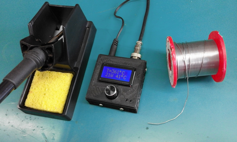
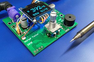
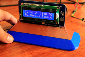
- Miniaturized size 2.6 inch square box

- Wide voltage range from 9V to 29V. Works on 60 to 150W solar panel 

- Adjustable real value soldering temp from 60* to 430* on the tip

- Adjustable stand by temp from 60* to the soldering temp value

- Adjustable time before entering stand by up to 360s

- Adjustable sound settings

- Adjustable back light intensity 

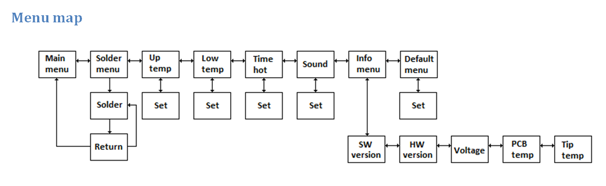
- Info menu providing details about the SW and HW versions. 

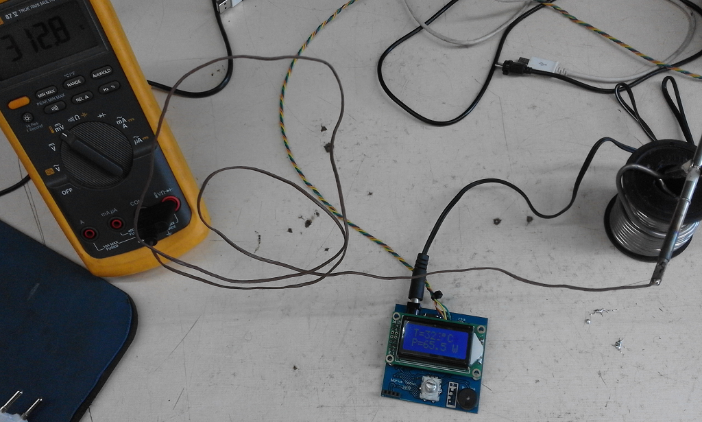
- Possibility of reading the PCB and Tip temperatures

- Possibility of reading the input voltage, tip current and tip power calculation

- Embedded alarms and error messages on the screen. Warnings for loose wires, disconnected aviator plug, overvoltage and tip heating element damage.

- Thermal shut down in case of over tip temperature or over board temperature 

- Reverse polarity protection for 5 seconds

- Set to default values menu

- Intuitive menu

- Single rotary encoder operation

- Low power consumption achieved by using the stand by function

- Long tip life

- Precision temperature control 

- Customizable

- Ultra fast operation and short heating time

Why build your own?

There are similar products on the market. For instance this one:

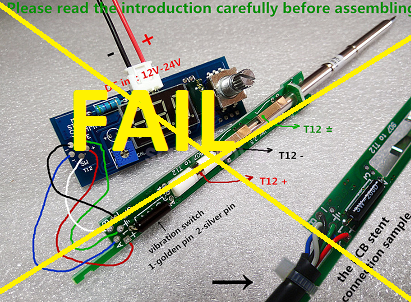
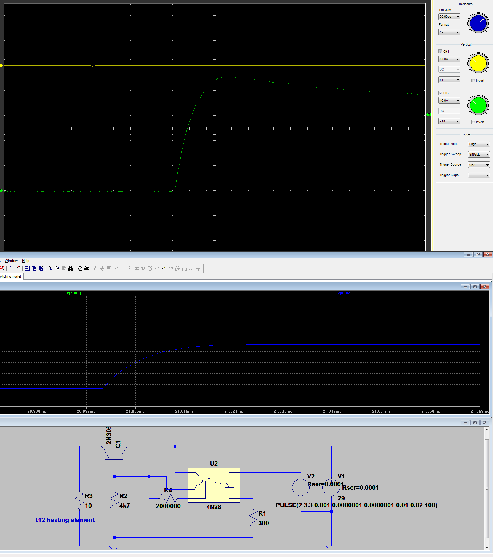
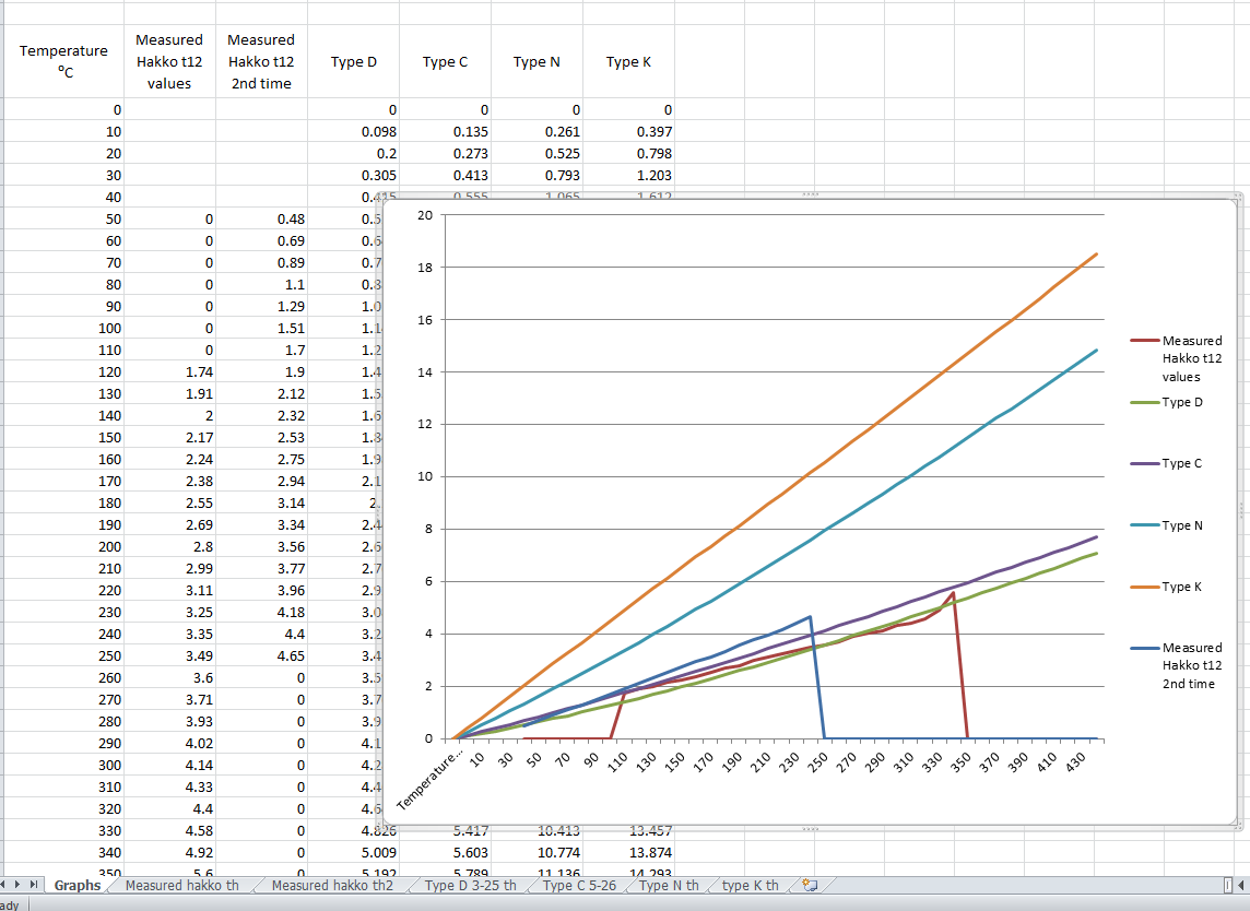
I bought one of this, but I just dislike it. The rotary encoder does not have proper SW debounce and the settings are sometimes decrementing when you want them incremented. The mV/*C setting corresponds to a type K thermocouple, but the actual tip has something like a type C one or something around 20 or 21mV/*C. This means that these funny soldering stations are displaying 350*C and they really heat up to 550 damaging the tip. The menus are just P01, P02.. and you never know what they mean when you need to set something. I just want something that I can trust.  

Firmware Build files.zip

Firmware - all files

x-zip-compressed - 500.69 kB - 07/27/2018 at 03:33

Download

Gerber export Marius Taciuc Jul 2018.zip

Gerber export including the drill file

x-zip-compressed - 63.02 kB - 07/16/2018 at 22:44

Download

hakko 4_4 backup.txt

4.4 Firmware version.

plain - 44.20 kB - 06/27/2018 at 12:14

Download

ms-xpsdocument - 111.97 kB - 06/06/2018 at 05:10

Download

hakko 3_3 backup.txt

V3.3 firmware version with back light control

plain - 43.71 kB - 06/06/2018 at 04:01

Download

View all 23 files

  • 1 × MSP430G2553 TSSOP 28pins MCU
  • 1 × LM324AD Amplifier and Linear ICs / Operational Amplifiers
  • 1 × 5.5mm DC connector Through Hole mount conecotr
  • 13 × 100n 0805 SMD
  • 1 × 220uF Electrolytic SMD

View all 34 components

  • STL files for the case

    Marius Taciuc01/13/2023 at 13:09 0 comments
  • Final layout

    Marius Taciuc07/08/2018 at 23:14 4 comments

    As promised, this is the final layout. Check the files area for the updated C3 version.

  • Final firmware update?

    Marius Taciuc06/27/2018 at 12:12 0 comments

    I managed to add the latest firmware update. After many struggles to achieve all the things that I had in mind, I am happily loading the 4.4 version. 

    - Better temperature control,

    - Fixed a few bugs

    - Better human interface

    - More intuitive

    - Back light control for the C3 hardware 

    Unless I find some other things that really need changing, I pretty much think of this version as being the last one. Stay tuned for the last update which will be the layout for the C3 hardware. Then I can consider this as being another successfully finished project. About the firmware, I have a final note. I am using IAR Embedded Workbench to flash the MCU. I tried Code Composer and it seems like the code is behaving a little bit different. The compiler takes up much more space for converting the instructions to machine code. Therefore, there are some segments of code that are running at different speeds and the things are not quite fitting together. 

  • Solar panel test

    Marius Taciuc06/13/2018 at 13:07 0 comments

    I made a test using a Xunlight 68W flexible solar panel just to see how this device behaves and it seems like it's working good. This is stretching the idea of portability to a new level. Check the new video for more details. 

  • User manual

    Marius Taciuc06/03/2018 at 10:34 0 comments

    I added the first draft of the user manual in the Files section.

    I think this provides new insight about the product itself and explains all the features better. Check the file and stay tuned for updates!

  • Updated firmware and hardware

    Marius Taciuc05/31/2018 at 10:51 0 comments

       I updated the hardware to version c3 and the software to v3.0. The new hardware uses a P channel mosfet and solves the heating problem. It also has the possibility to control the back light intensity from software. Check the files. 

  • Switching time and snubber?

    Marius Taciuc05/11/2018 at 06:29 0 comments

    In the following hardware version I really need to include a snubber for the Mosfet and to make the rising and falling slopes stiffer. I tried different solutions, but it seems like I need to go with a much faster optocoupler. Check the files for the LTspice simulation with bipolar and Mosfet transistor

  • Hakko t12 thermocouple is not Type K!

    Marius Taciuc04/19/2018 at 06:45 7 comments

       I can tell you that I searched a lot on the internet on every corner I could find and I only came across speculations. No argument or statement supported by some measurements regarding the type of the Hakko t12 tip thermocouple. 80% of the posts out there would say it's type K and the rest will say it's not Type K, but they won't say anything about what is it.

       Well, I am ready to support my theory with some facts. First of all, this is how a tip structure looks inside. I took a look inside of one of these tips which paid with it's life for science. Then I draw this as accurate as I could. In what comes the graphs, I made a couple of sets of measurements and compared these measurements with all the known and most common thermocouple types on the market. they look like this:

       I will post a video to show you how I measured these values, but until then, I can tell you that the 1st measurement was made using another soldering station as a heating element and a Fluke 87-V with original thermocouple as a temperature measuring device. The second measurement was made in a bowl of heated oil. I firs heated the oil to about 300*C and then I placed the Fluke's sensor and the tip in the same bowl of oil. I read the voltage values generated by the hakko tip using another Fluke 87-V set to high resolution mode. 

       I have to admit that this method is not very precise and you can see this from the two different measurements I made. They came to be so different, because of the temperature gradient in the hakko tip. The higher the temperature difference between the heat source and the environment, the larger the error. This conducts me to the logical conclusion that I must approach the right measured values at lower temperatures. If I look at the graphs, I can see that at lower temperatures, my measurements are overlapping with the graph of the Type C thermocouple. If I had a thermal chamber I would definitely take some more accurate measurements, but until then, I can tell you one thing for sure: this thing is definitely not Type K. Not even close. 

       I remember reading somewhere on the internet some contradiction related to this. A guy was saying that is Type K and that he measured it and it had around 20uV/*C at some certain temperature. Well that's a misleading statement. Type K thermocouples are having around 41uV/*C at 1000*. 

       I implemented the 21uV/*C value in software and later on, I tested the system with different values such as 19uV/*C, 20uV/*C and others. I was measuring the tip temperature using a Fluke while testing it and I can tell you that the hakko tip seems to be pretty linear. Moreover, I managed to achieve a less than 10*C difference between the temperature displayed on the screen of the soldering station and the externally measured temperature of the tip. And I expect that the Fluke thermocouple would have it's own mass and act like a heat sink on it's length. Therefore it's good to see the heating element and the core of the hakko tip at a temperature greater with 10* than the tip itself. 

       It actually makes sense to have the heating element made out of some tungsten alloy rather than nichrome, because the design is airtight and tungsten is cheap. Type C thermocouples are 95%W/5%Re–74%W/26%Re. The heating element is probably made out of 95%W and the other wire that comes form the socket and joins with the heating element creating the thermocouple is probably 74%W/26%Re. Problem solved.

       This brings me to blaming these failed soldering station kits again:

    I don't know who designed these, but they only have the possibility to set the uV/*C from 41 down to about 30 from the internal menu and this says it all. 

  • Added PCB pictures

    Marius Taciuc03/26/2018 at 23:07 1 comment

    Now it's the time to keep changing components and to run some tests. As you noticed in the picture, I used a 16*2 LCD until I had the 0802 ones. Check the gallery for all the pictures and stand by for more updates and some software files. 

  • Added layout

    Marius Taciuc03/22/2018 at 23:50 0 comments

    Check the Files area for the layout files I added today

View all 11 project logs

  • 1
    How to flash

    - Keep the soldering station externally powered via the DC connector

    - Connect your MSP launchpad to the usb port of your computer

    - Connect the flashing cable like in the above image

    - Run IAR embedded workbenck

    - Click Project/ Options/Debugger to make shure your settings are right and you can connect to the launchpad

    - Make shure the Driver is set to FET Debugger and not to Simulator 

    - The following settings must be like in the images below:

    - Click the Download and Debug button and if it's connecting you should see the two progress graph bars incrementing, signaling that the software is flashing. The LCD back light should be always off during flashing if you have the latest hardware (C3) I posted on the project's page.  

View all instructions

Enjoy this project?

Share

Discussions

Loled wrote 07/14/2022 at 14:01 point

Hi, sorry for posting on this old thread. 

I'm designin my own soldering station and I found you project. I was wondering how do you performed the thermocouple cold junction compensation? 

As far as i saw you don't implement it, but may be it's not nessecary? Do you know how much the accuracy of tip temperature measurement is degraded?

  Are you sure? yes | no

Marius Taciuc wrote 07/15/2022 at 05:38 point

Usually, these soldering iron tips were not designed to be cold junction compensated. They are not having any room in the handle for adding an extra temperature sensor and a metallic block. Thinking about it, I realize that I don't think I ever saw a single soldering station out there that has anything like this. And the reason there is none out there, is the fact that the tip temperature doesn't need to be very accurate. And it varies a lot. when you touch the soldering iron to the board, it's temperature drops 50*C before you manage to start the self regulating loop and the heating element. Most of the soldering irons on the market are not even displaying the temperature very precise, because the numbers are simply flickering too much. They add a lot of delays and software filters to the screen temperature on purpose. Good luck with  your design and post pictures when you're done.  

  Are you sure? yes | no

Loled wrote 08/07/2022 at 21:08 point

Thank for answering and sharing about your project Marius!

Yes I agree that a 1°C accuracy isn't required, however 50°C seems to be a lot? on some weller specs I heard about 10°C drop, but I never conducted measurement by myself. If I have time I will try to measure it; I have a solomon SL20, and at work a weller station with micro WXMP iron (to deal with 0201 SMD :) ) .

To get correct soldering capabilities with such temperature drop, dont you have to set the iron temperature higher? At some eletronic manufacturer services place, I know the temperature or irons is 'calibrated' (the operator can't change the setting regards to his workpiece), thus the drop has to be minimal. By design, the iron manufacturer work to reduce this drop (as metcal, weller/JBC/other with small integrated heater in tips).

I have seen in unisolder design that the PACE TD100 has a cold compensation sensor in the handle, but I heard it's the same for a few weller irons (latest models).

Whatever I mainly target an iron with T12 tips (because of lower cost), but I may try to add a compensation sensor (in a custom handle) to get better time-temperature responses, if required….

  Are you sure? yes | no

kempil wrote 06/25/2021 at 20:01 point

Hi Marius good project thank you

  Are you sure? yes | no

Marius Taciuc wrote 06/26/2021 at 06:26 point

Good to hear that you like it. Hoping that you will try to build your own and replicate it, I wish you to have fun. 

  Are you sure? yes | no

oto wrote 01/23/2021 at 09:43 point

Hi Marius. ! it's me again. How you been? Hope great.
I have  gotten the Lauchpad finally from Asia.. I installed Energia IDE to program the MCU only practice to load the code,  but I got this problem in code 4.4 version.

----------------------------------------------------------------------------------------------------------------------

Energia: 1.8.7E21 (Windows 10), Board: "MSP-EXP430G2 w/ MSP430G2553"

Build options changed, rebuilding all

sketch_jan23a:116:15: error: '::main' must return 'int'

sketch_jan23a:116:15: error: '::main' must return 'int'

exit status 1
'::main' must return 'int'

----------------------------------------------------------------------------------------------------------------------

There's a way I may email you? I can't figure it how to use Code composer using the Launchpad as programmer to flash the MCU.

I have no gotten answer from IAR for a student License or something alike. So the only option to flash the MCU is with code composer, but I think need you may help me out.

this is my email: otoniel_amigo1@hotmail.com if you may send email some steps in Code composer or any other option it would be great. I can't afford the IAR license.

By the way you have back to the youtube channel that is great, Glad you posted. Thank you so much again for this project.


  Are you sure? yes | no

oto wrote 02/10/2020 at 13:48 point

Thank you for such amazing shared project. Hope you're doing great Nowadays. Silly question, May you point me Which or What software get. IAR have many Technologies options, and all of them ain't free. Free 30 trial version are limited to program only 4 kbytes, limitation of Source code for runtime libraries, so if you may light me which software did you use? it would be great! have a wonderful day.

  Are you sure? yes | no

Marius Taciuc wrote 02/11/2020 at 00:34 point

Good morning, Oto. You basically have only two options. One of them would be Code Composer. Code Composer is free and once you get used to it, it can prove to be a good tool. The other option is IAR. I know they have this code size limitation, but I remember you could contact them at some point and apply for an educational license or something. I have no idea if they still provide this service anymore or how fast they are in replying to your emails. 

  Are you sure? yes | no

Batmonstro wrote 10/14/2018 at 11:18 point

Good morning, Marius! I'm so glad you answered me so quickly !!! To ask you a new question and in the same project, I'm basing myself on the Hakko Revenge Schematic C3.XPS OK ??? I would like to know if the diodes D304 and D305 are general purpose diodes such as 1N4148. No more, thank you again.Detalhes

  Are you sure? yes | no

Marius Taciuc wrote 10/23/2018 at 06:55 point

Sorry for my delayed answer. I've been out for a while. The diodes are both BAV70. I wrote A4 sot-23 on the components list which means the same thing. They are rather rectifiers than switching diodes because they are working at a very low frequency. 

  Are you sure? yes | no

Batmonstro wrote 10/23/2018 at 10:09 point

Marius, muito obrigado mais uma vez!!!

  Are you sure? yes | no

Batmonstro wrote 10/12/2018 at 13:23 point

Detalhes

Good morning, noble friend! Great project !!! Could you post the material list ??? I'll see if I can ride this station. Thank you very much...

  Are you sure? yes | no

Marius Taciuc wrote 10/13/2018 at 07:07 point

I did now. Wish you luck. And when you finish it post some pictures here, alright? I only placed the minimum required components. I assumed that instead of the second LM317 everyone would like to use a 1117-33 which does not require extra resistors, and so on. 

  Are you sure? yes | no

AABatteries wrote 06/21/2018 at 09:34 point

Hey Marius! Great project with excellent execution, well done! One question: do you think you could add a low voltage alert / disable heating on low voltage? That would make it perfect for use in the field with LiPo batteries (as commonly found with drone enthusiasts, mainly with an XT60 connector). I would be glad to make a pull request for you with a modified enclosure with a XT60 connector if you like :)

  Are you sure? yes | no

Marius Taciuc wrote 07/16/2018 at 22:54 point

This is not a bad idea. Hmm. What should be the low voltage disconnect threshold? 11.2V?

  Are you sure? yes | no

AABatteries wrote 07/17/2018 at 12:50 point

I think most hobbyists use either 3S, 4S and 5S batteries. So low voltage thresholds should be set in the range of 3.0 - 3.3V per cell (usually accepted as the lowest voltage), so 9.9V for 3S, 13.2V for 4S and so on. I think you might implement the threshold to be based on input voltage, but probably it's easiest to just create a menu where you can manually set the value. I'm really impressed as to how professional you project is Marius! Hats off to you!

  Are you sure? yes | no

Orlando Hoilett wrote 04/28/2018 at 11:04 point

This is really cool.

  Are you sure? yes | no

Marius Taciuc wrote 04/30/2018 at 11:07 point

Thanks.

  Are you sure? yes | no

Rein wrote 04/19/2018 at 19:49 point

Great project! Could you also provide the schematics as pdf? 

  Are you sure? yes | no

Marius Taciuc wrote 04/27/2018 at 05:16 point

I uploaded an *.xps file with the latest (C2) schematic variant. Does this help? 

  Are you sure? yes | no

Rein wrote 04/28/2018 at 16:12 point

Yes, thanks!

  Are you sure? yes | no

Similar Projects

Does this project spark your interest?

Become a member to follow this project and never miss any updates