0%
0%
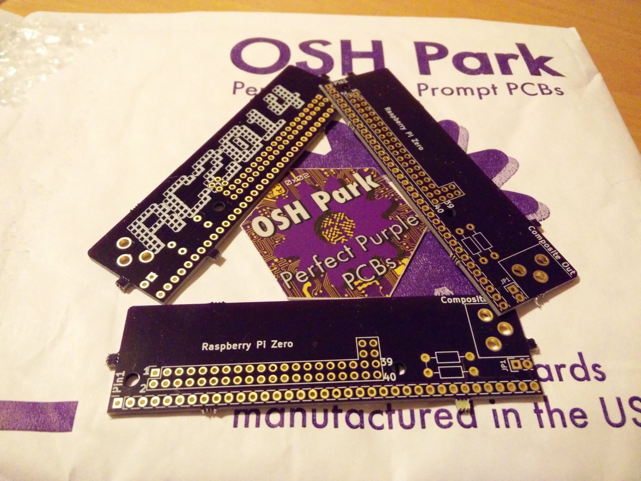
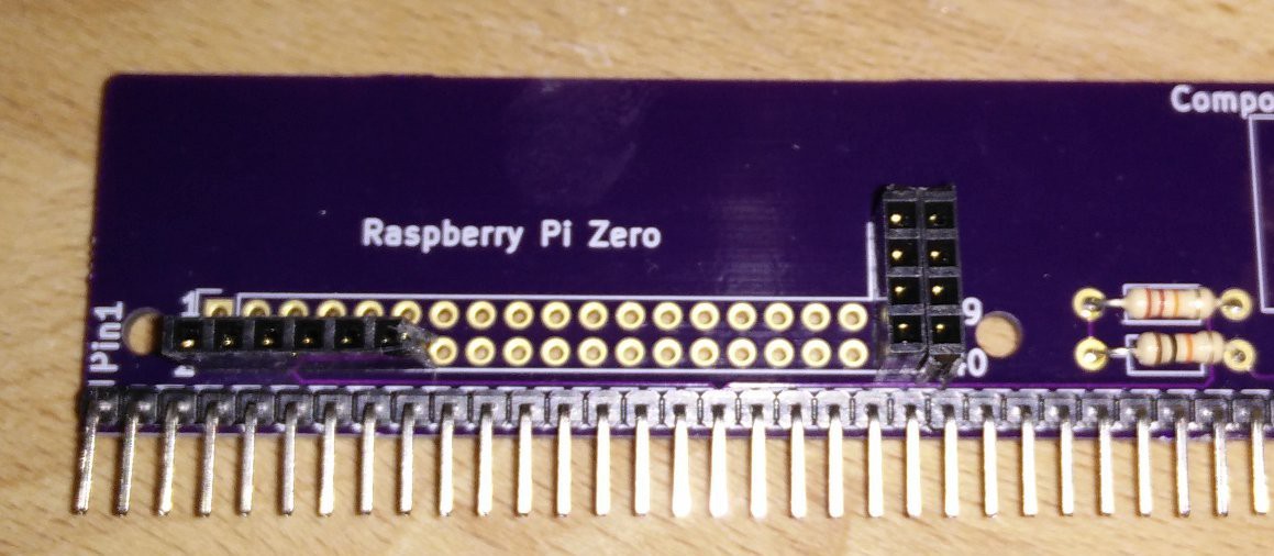
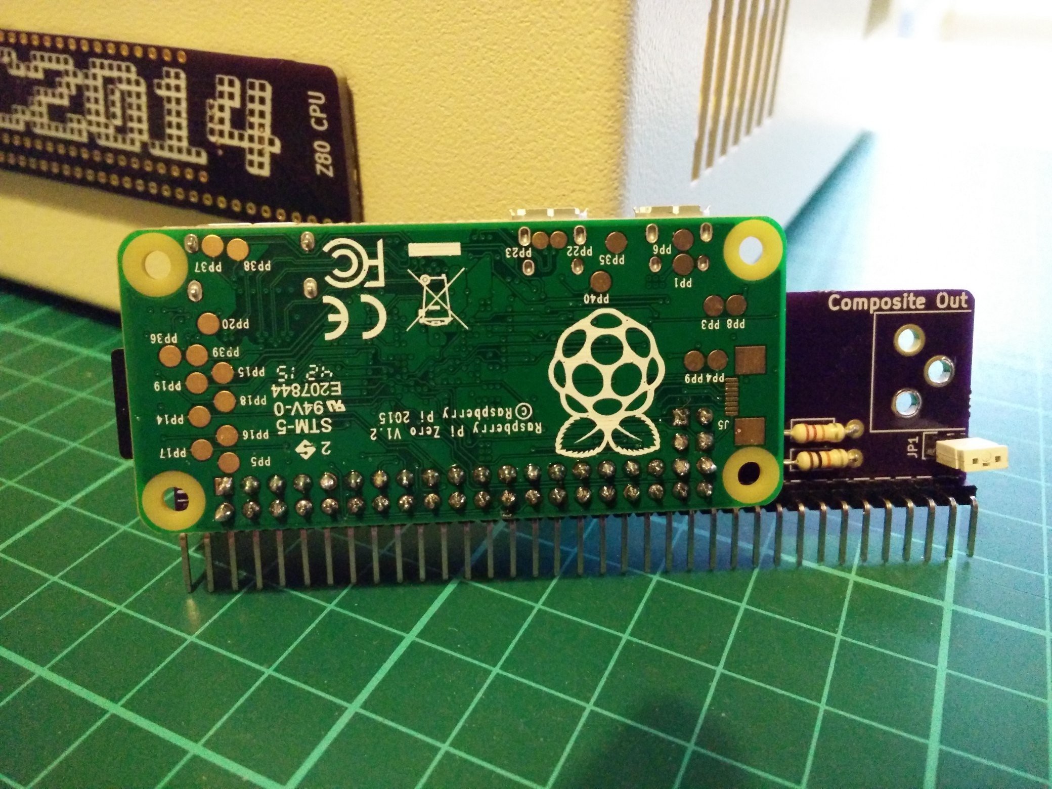
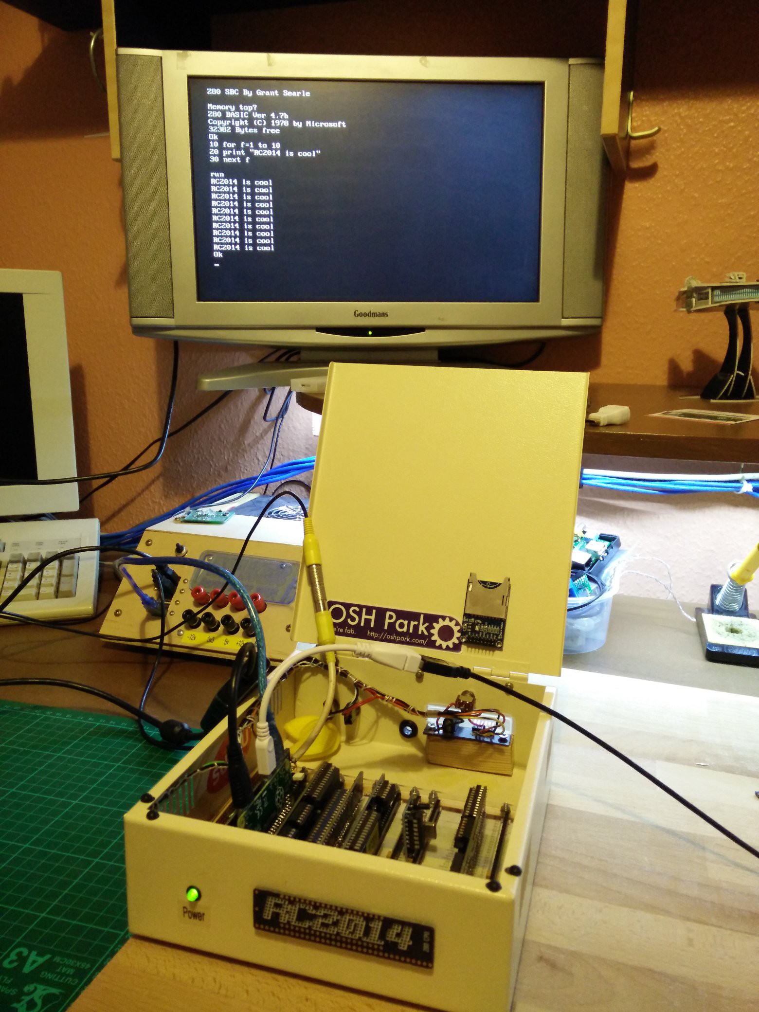
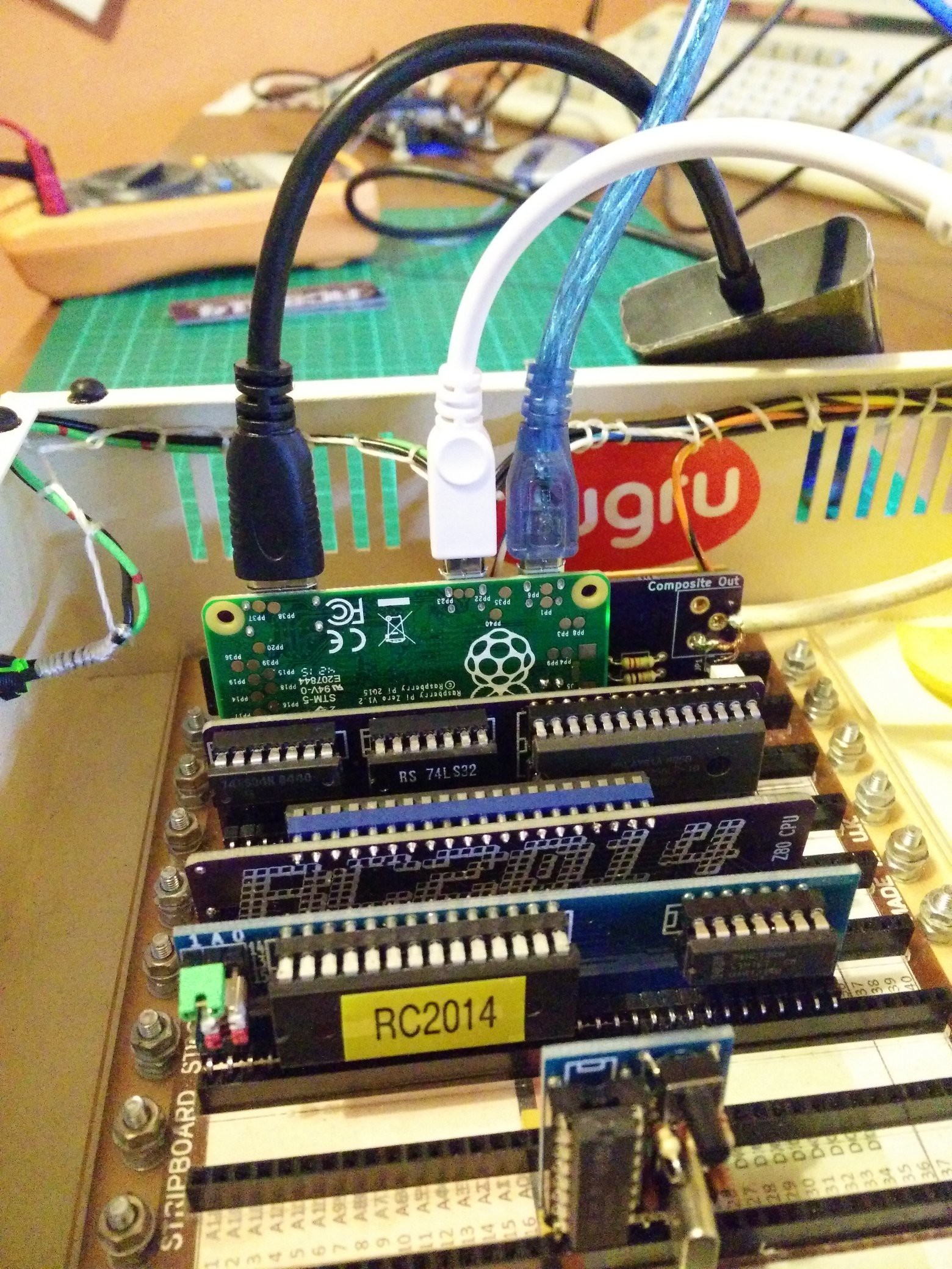
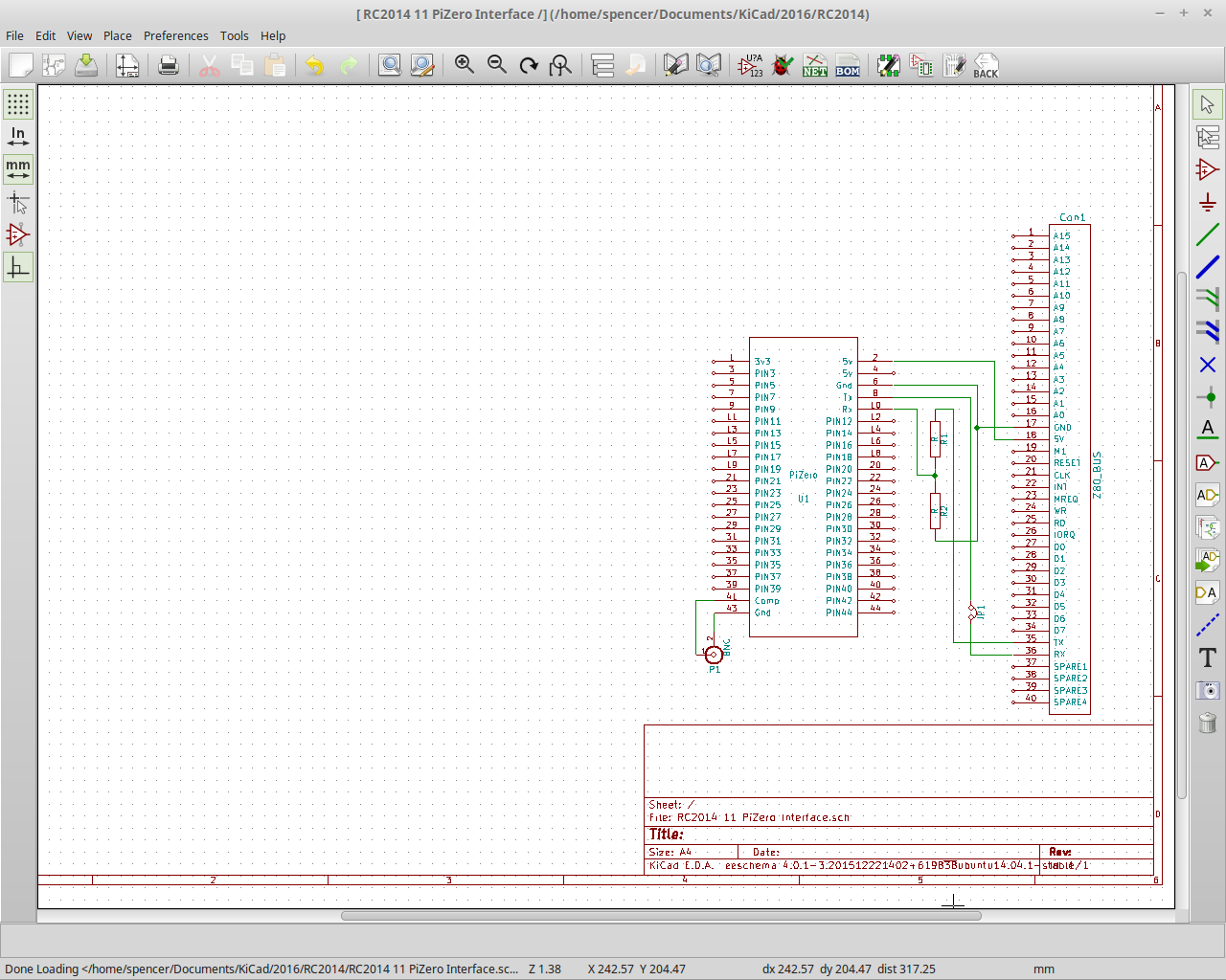
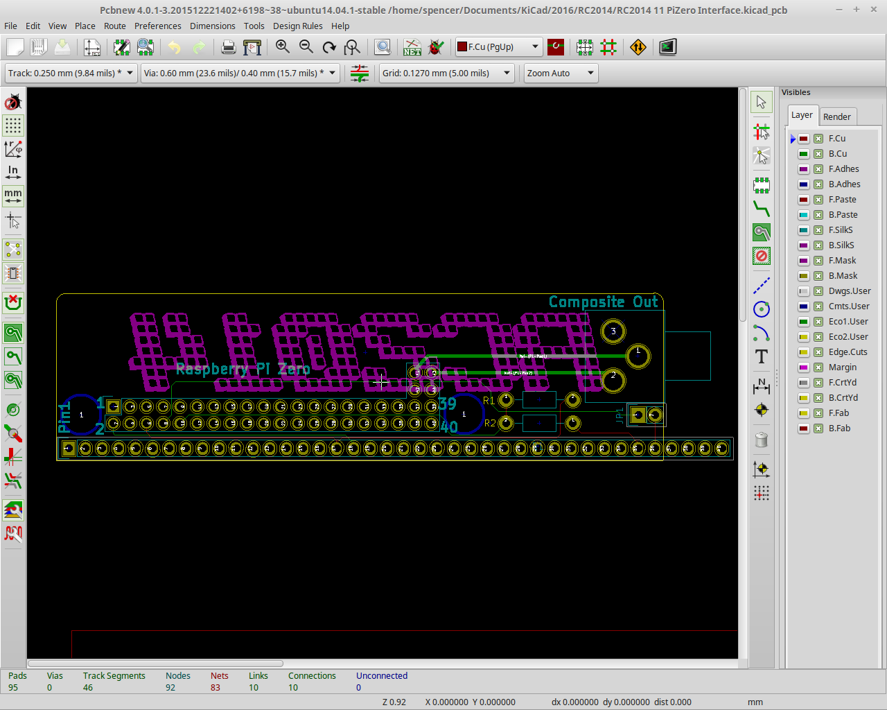
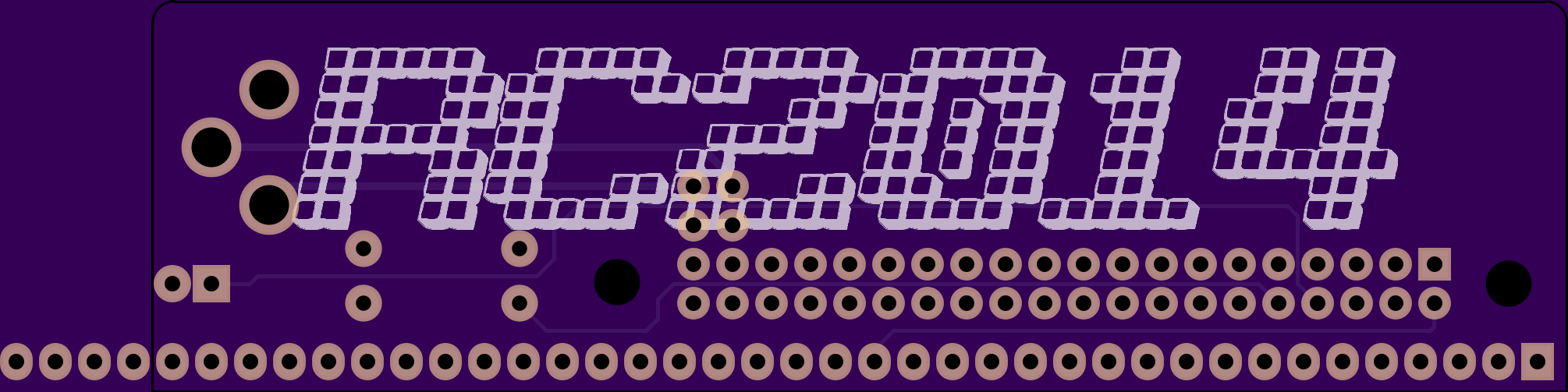
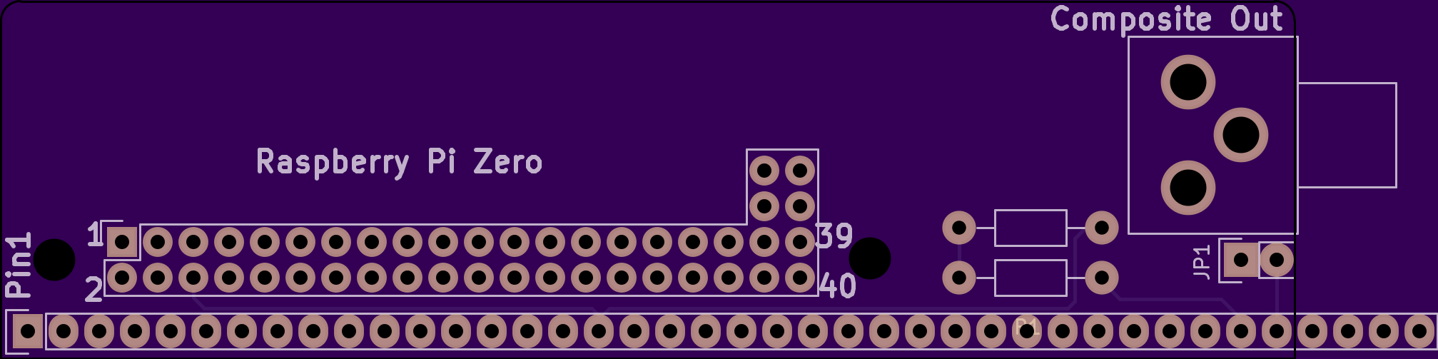
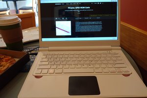
$5 Graphics Card For Homebrew Z80
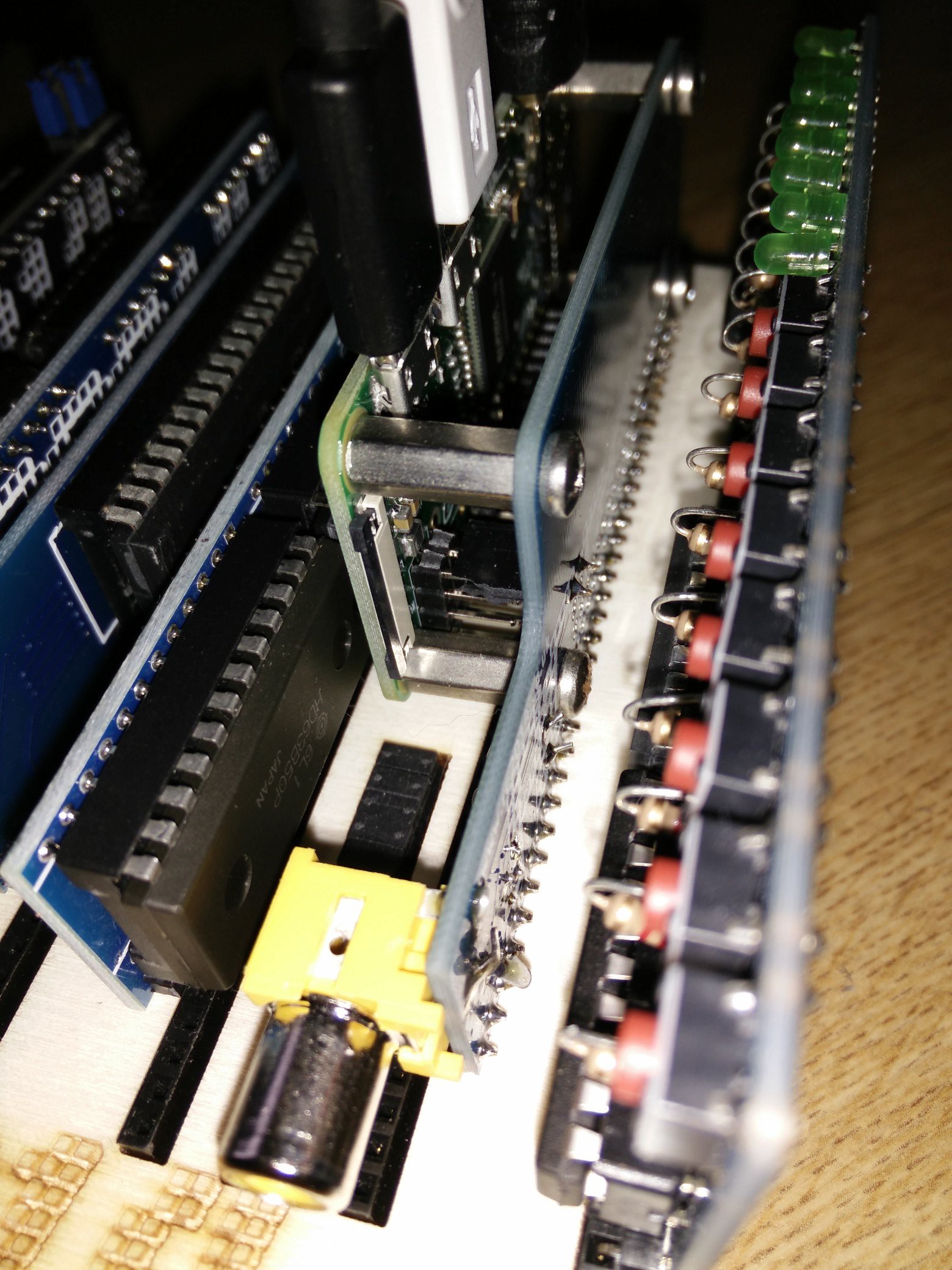
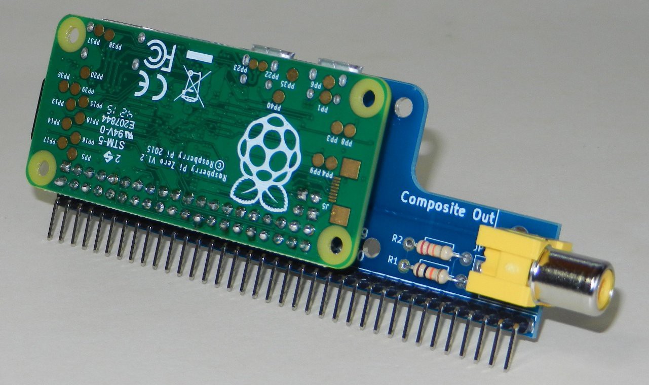
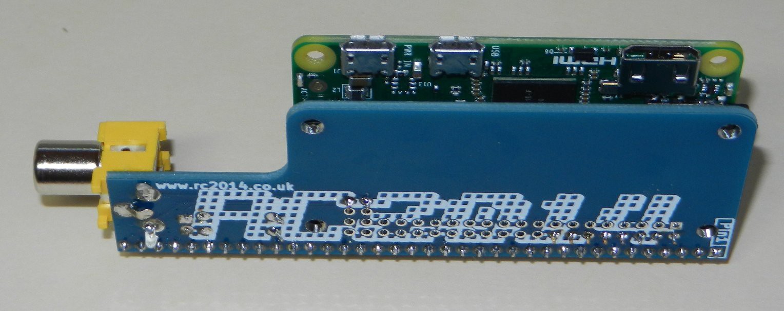
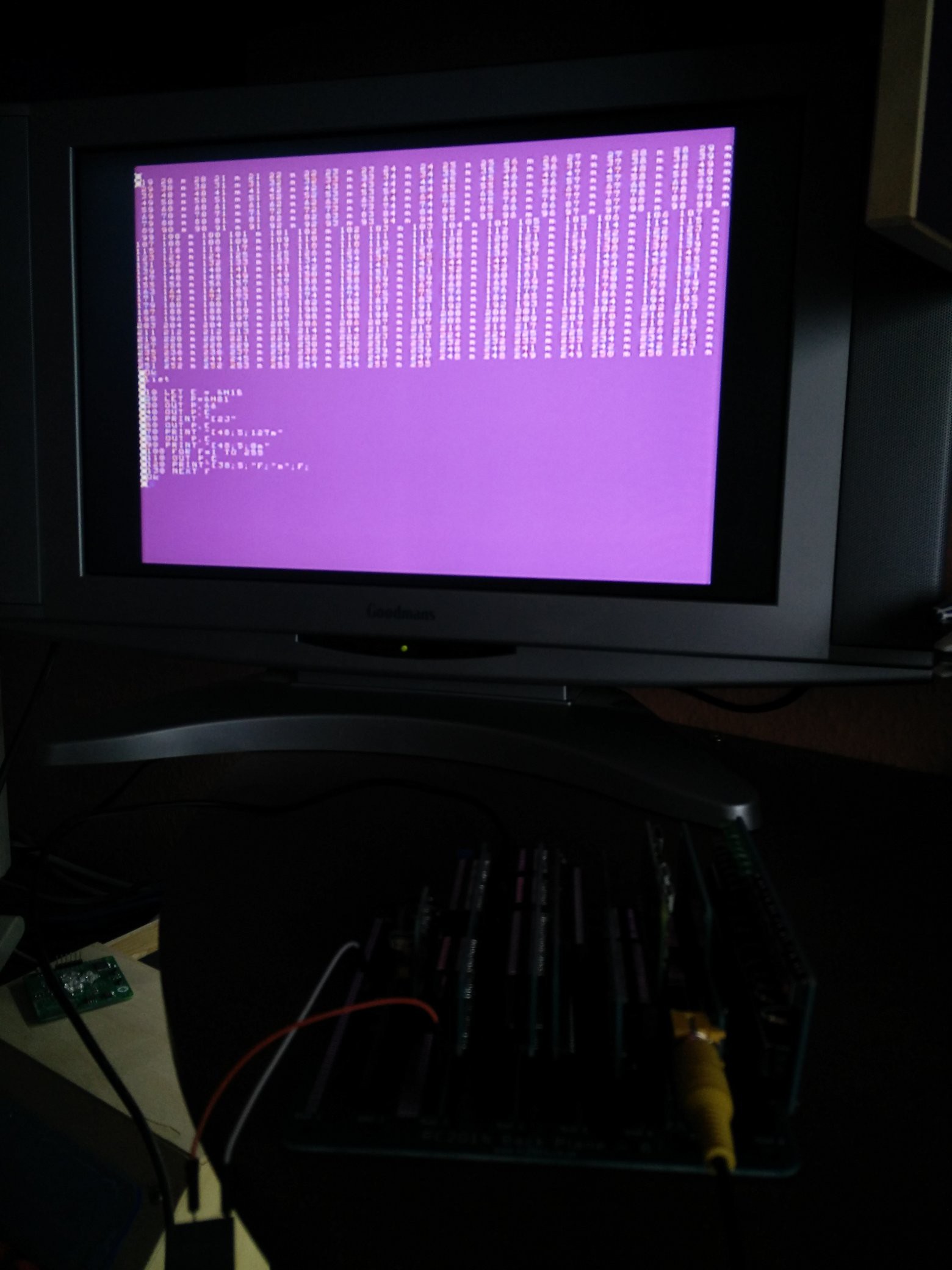
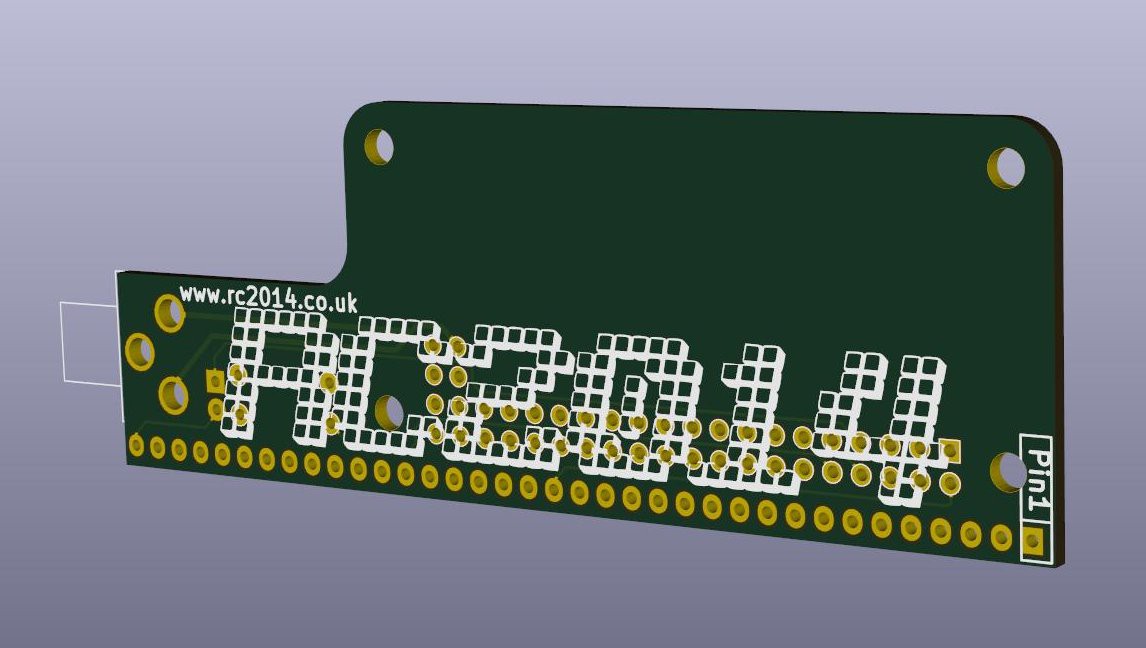
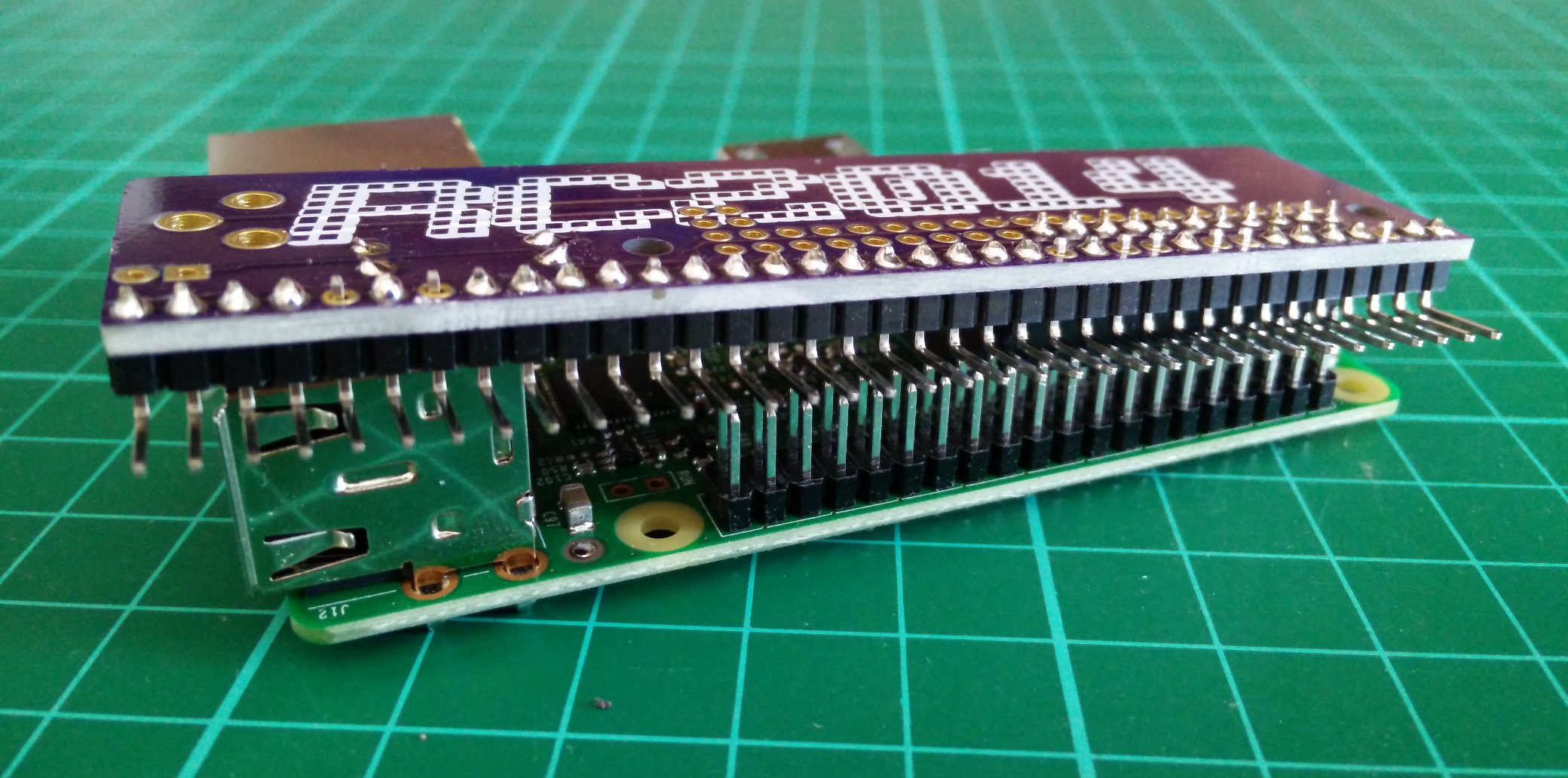
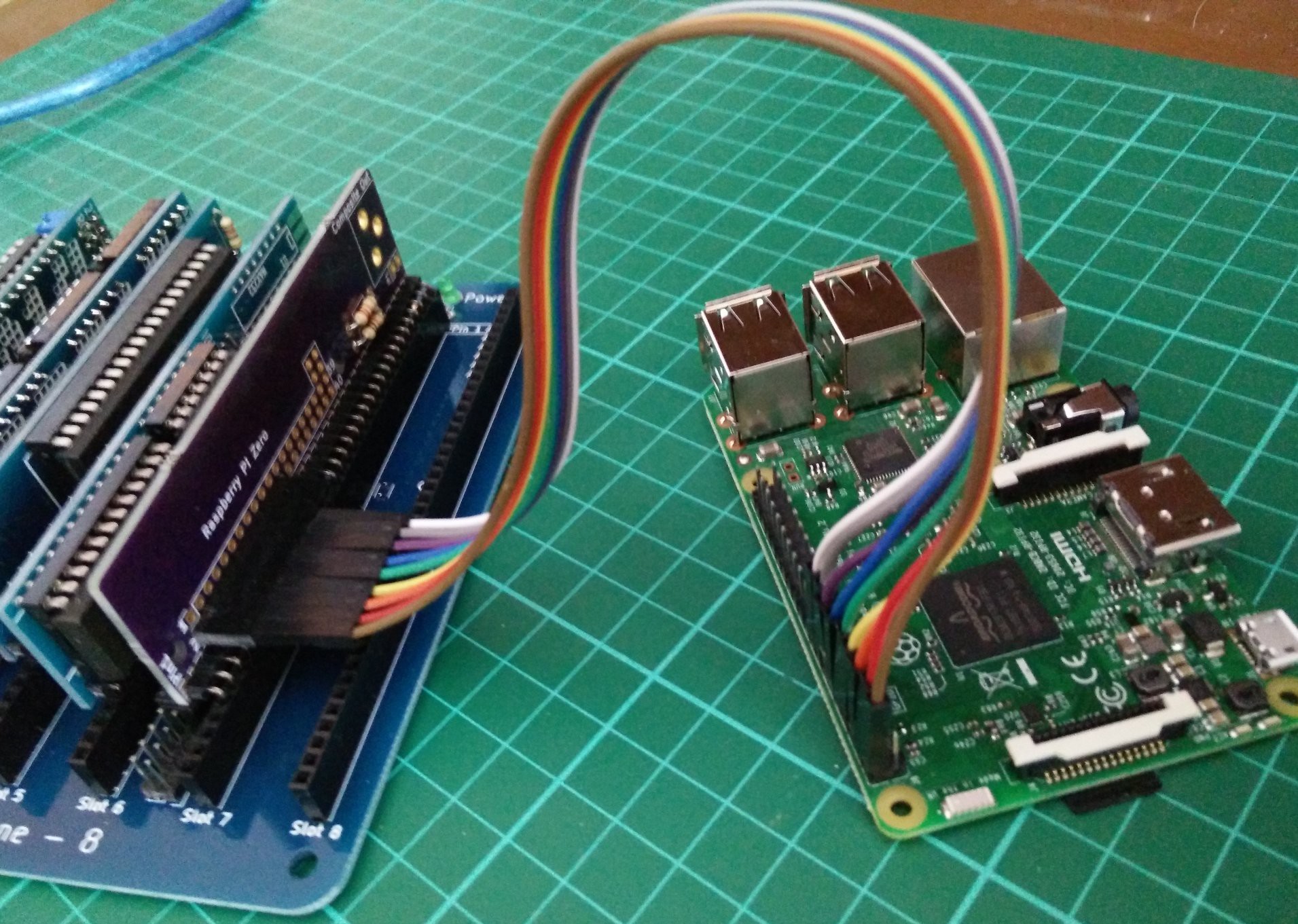
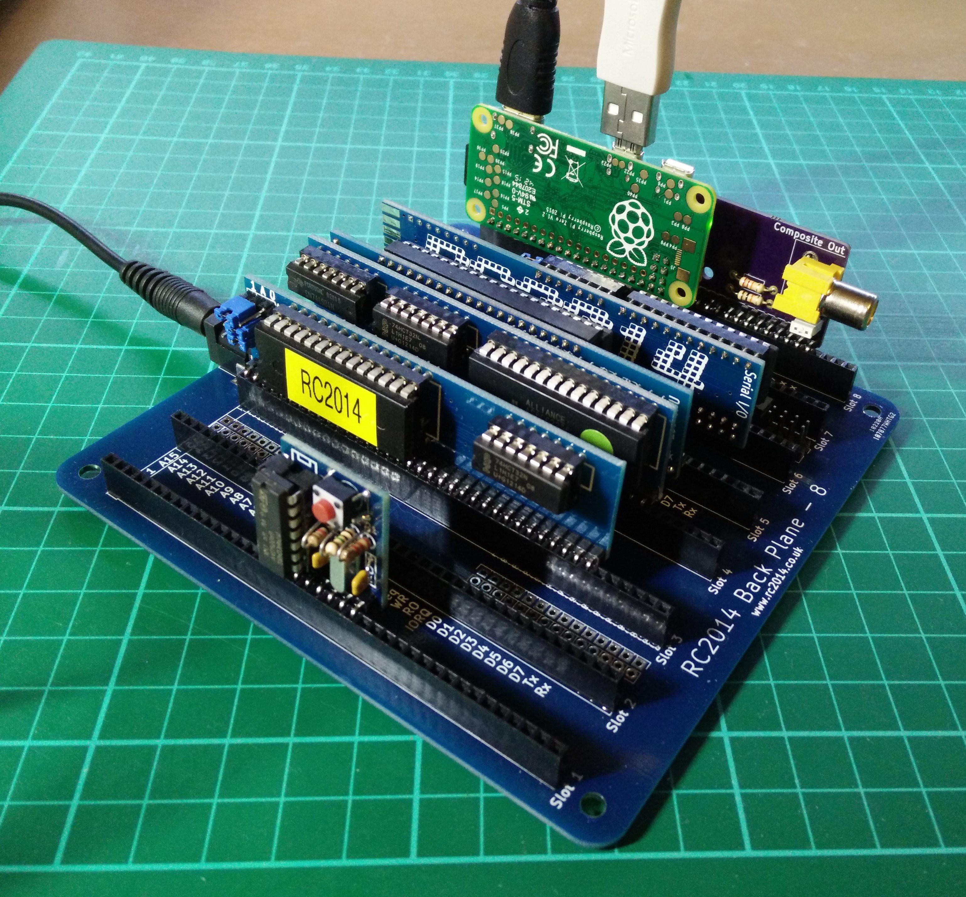
Using a Pi Zero, I want to create a cheap keyboard interface and graphics card for my RC2014 homebrew computer
 spencer
Become a Hackaday.io member
Already have an account? Log in.
Just one more thing
To make the experience fit your profile, pick a username and tell us what interests you.
Pick an awesome username
hackaday.io/
Your profile's URL: hackaday.io/username. Max 25 alphanumeric characters.
Pick a few interests
Projects that share your interests
People that share your interests


 Maksim Surguy

Not function Rasberry PI W ver.1.1