Close
0%
0%

Raspberry Pi Heating System

A heating system based on the Raspberry pi to control relays and valves.

Similar projects worth following
I live in a rural area where the electricity supply isnt 100% reliable and our heating system is powered by a timed relay (you know, one of the cheap ones with all the notches). I noticed after a few times after the house was without power that the timer was off by a few hours and was getting tired of resetting all the buttons as the temperature changed. I had read about the "Nest" system a couple of years ago and decided that I would start building my own version using the Raspberry Pi to control the relay in the same way that the timer did, only with more automation and more user-friendly, and hopefully controllable over HTML so I can turn it on when its especially cold or turn it off when we're away.


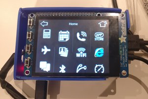
The RPi will have a touchscreen interface with a selection of buttons which will change depending on the mode, both in color and wording. "Off", "Automatic/Constant", "Timed", "Boost/Timer Countdown", "Upstairs" and "Downstairs". The touchscreen interface will be programmed using python and pygame to display on the screen.

The Pi will also have nginx installed on it and host a password protected php website which will interface with the touchscreen using xml. When a HTML command is issued the command will be sent over TCP to the python program which will be listening on a port for HTML commands. The webpage will refresh every 5 seconds to ensure that no conflict occurs and will not write to the XML file directly.

The Pi will also act as a TCP server to receive messages from ESP8266s around the house with thermometers and connected to one will be an arduino pro mini which will control stepper motors to control the upstairs/downstairs zones.

Another ESP8266/Arduino with 433mhz module will be outside the house on the oil tank with an ultrasonic sensor to measure the level of the tank.

Modes

"Off" - this will turn the heating system off, turning off all relays.

"Automatic/Constant" - Automatic mode will control the zones according to set temperatures received from various ESP8266s around the house, while Constant will turn everything on and allow the burner to work constantly only turning itself off when the water temperature/pressure has been reached.

"Timed" - this enables a timed mode, first displaying a screen with a series of blocks of 15 minute slots starting at 00:00 and ending with 23:45. Each slot can be highlighted and when ok is clicked, the blocks are saved to a variable and in a json file in a series of True/False values. When the time reaches a key time (eg 00:15) it checks the variable and if its true and the relay pin is false it enables the Relay and vise versa.

"Boost/Timer" - This allows a quick boost in 30 minute intervals (eg pressing 3 times will add 90 minutes). The button display will change to a countdown or perhaps show a countdown below the button in plain text. Pressing any other button other than "Downstairs" or "Upstairs" will reset the timer and enable that mode.

"Upstairs" - This sends the TCP message "upstairs" and a 1 or 0 to indicate on or off, to an ESP8266 to enable the "Upstairs" zone. This then turns a pin High which is read by an Arduino pro mini. The arduino enables a transistor to allow 12v power to flow to a stepper motor and then issues the steps to a stepper controller. The stepper controller will turn a 12v stepper motor 90 degrees, turning on/off a butterfly valve which is at the base of the pipe that is fed to the radiators upstairs. The ESP8266 will wait until the arduino turns a separate pin high before it sends a TCP message back to the Pi to indicate that flow to the zone is now open/closed. In the event of a powerdown the arduino writes the current position to eeprom once completed and writes a pin High/Low to indicate if that zone is active. When booting up the ESP8266 reads this pin which changes a boolean to True/False. When a "Status" TCP message is received from the Pi it sends back the current zone status.

"Downstairs" - This sends a TCP message to the same ESP8266 as in the "Upstairs" command, except the message is "downstairs" which turns a different pin on the ESP8266 to High and waits for a different pin to go High.

When the main project is finished I'm hoping to install a few other ESP8266s on radiators in key rooms which will control a stepper to turn the thermostatic valve on each radiator when it reaches a given temperature. The temperature will be set by a rotary encoder and displayed on an LCD screen at each ESP8266. Each of these ESP8266s will report back to the Pi and will be sent Enable/Disable values according to the status of the timer.

At the moment powering each of the ESP8266s is an issue as each radiator may not be close to a power socket. One option I am currently...

Read more »

RPiHeatingOilSensor.zip

The Oil Sensor (433mhz version & TCP versions). Component List: HC-SR04 Ultrasonic Sensor DS18B20 Thermometer Headers (male and female) DuPont Connectors Various Wiring Component List for 433mhz Version: Arduino Pro-Mini RXB6 433Mhz SuperHet Receiver FS1000A 433Mhz Transmitter ZS-042 (DS3231) RTC Component List for TCP version ESP8266-ESP (07 or 12) 2x 3mm*4mm momentary switch 6x 10K (0806)resistors 1x 6.8K (0806) resistor 1x 3.3K (0806) resistor 1x 2n7000 mosfet 2x 10uF/106 (0806) capacitor 1x 100nf/104 (0806) capacitor 1x 1000uf electrolytic capacitor 1x AMS1117 3.3v 1x LM7805 1x 10uf electrolytic capacitor 1x 1uf electrolytic capacitor 1x 100K 1/4 watt resistor 1x 6.8K 1/4 watt resistor PCB for etching

Zip Archive - 164.33 kB - 05/27/2016 at 10:54

Download

RPiHeatingInstall.zip

Beta version for Raspbian Jessie. Should work on most SPI based touch screens. Make sure to set up Jessie for your touchscreen and take note of pins needed. sudo raspi-config Select Advanced -> A3-Memory Split -> 16 Select Advanced -> Device Tree -> Yes Download zip and place in /home/pi/ unzip RPiHeatingInstall.zip sudo bash /home/pi/RPiHeatingInstall/setup.py follow instructions. Component list: LED red x 1 LED green x 1 SPI touchscreen (this is mine https://www.raspberrypi.org/forums/viewtopic.php?f=64&t=48967 but should work with most SPI based touch screens) Wifi adapter/ethernet cable 5v Relay Module SD Card (4gb + should do) Wires dupont connectors 433mhz receiver + transmitter (optional)

Zip Archive - 184.75 kB - 05/27/2016 at 10:41

Download

Sources.md

List of sources for code and libraries

md - 2.70 kB - 04/25/2016 at 10:58

Download

Licence.txt

GPL v3.0

plain - 34.98 kB - 04/25/2016 at 10:58

Download

  • 2 × Arduino Pro Mini
  • 1 × ESP8266-12E
  • 1 × ESP8266-PCB BreakoutBoard
  • 17 × Headers
  • 1 × AMS1117 5v

View all 48 components

  • Log No. 4

    Colin Conway05/27/2016 at 11:23 0 comments

    Finally got the ESP8266 code and wiring sorted. I used a board schematic I made a while back as a breakout for the ESP8266-12E so I could use it to control some neopixels (one pin has a 2n7000 as a level converter). I've modified it a bit to include some additions for this board (most notably the header for a jumper to enable deep sleep mode).

    I also created an IO board out of perf board to handle a 5v regulator (your bog standard LM7805) as the HC-SR04 needs 5v to take all the incoming devices, ground and power them and to handle the voltage divider for the battery level reading (it was easier than designing and etching a totally new board). Only issue with this setup is there are a heap of wiring back and forth from the ESP board to the IO board. I'll design one and upload the schematics when I haven't got a heap of deadlines to meet!

    This certainly is more reliable than the 433mhz version, probably due library used in python, or maybe the amount of threads (btw I'm testing this on a Raspberry Pi B rev 2 board to ensure its compatible with ll Pis). I was actually tempted to use an ATTINY85 as a 433mhz proxy, with software serial to communicate with the pi and connect the radio devices to that instead, but I thought I was getting way to complicated for that.

    Oh and I fixed the weather issue, apparently Yahoo changed their API so the library I was using (which hasn't been updated in some time) couldn't communicate with it. I've also added a python script to change the location of the weather report in the setup script. Completely forgot it was set to my locale in the script!

    Next job is to resize the screen contents according to the resolution of the screen attached. I'm thinking I might get a 800x600 5inch screen just to test, but that wont be for another month or so before it arrives.

    Oh and I'm thinking maybe of adding to the project to include it in the next round of the Hackaday contest (citizen scientist), maybe add MySQL or MariaDB to the Pi and logging everything from the amount of Oil used compared to the amount of minutes the heating is on. Maybe throw that together with the temperature difference between outside and inside the house and plot the whole thing as an efficiency thing or maybe output the CO2 produced. Not sure - worth a think I think!

    Onward and Upward.

  • Log No. 3

    Colin Conway05/19/2016 at 15:57 0 comments

    OK my ESP8266 ESP-07 arrived. Signal with the onboard ceramic antenna wasn't enough so I made a bi-quad antenna (using this site as a basis for it http://martybugs.net/wireless/biquad/) only I took an old antenna from a laptop and desoldered the antenna from that. Not exactly part of the project but I might throw up some images of what it looks like. I've been kept busy with other things so I should have time to throw the OilSensor together based on this device. I've already etched out a board from a schematic I put together in Eagle, so I'll put that up next week, and hopefully I'll have some code to go with it.

  • Log No. 2

    Colin Conway04/25/2016 at 13:29 0 comments

    Added a few updates and bug fixes for various issues. I've put in an oil sensor node for a horizontal cylinder shaped Kerosene tank. At the moment I've only included the ASK radio method of data transmission using 433mhz modules, but I've an ESP8266-07 on the way (the one with the external antenna), so hopefully that will be able to reach the wifi router and send the data via TCP (which should make it much more reliable).

    One of the main improvements is adding a separate thread for screen control, which gets rid of the bug that prevented any changes while the screen was in Timed mode. I've also added headless modes so the heating system can be controlled by HTML only with no need for a touchscreen at all (which I still have to test properly).

    I've added an extra OK box in the Timed screen that's easier to click and set up the weather feeds as individual try and except methods to pull the data, so if one piece of information isn't available the rest can still be displayed. I've also included a python script to re calibrate the touchscreen if necessary.

    To the html I've added readouts for the oil sensor and fixed a bug when saving the times via HTML as the json was not reloaded in the running thread, meaning that the user had to click on the Timed button on the screen or reboot before it was reloaded.

    Sources of the code has been added along with a list of the libraries for the arduino sketches that are necessary for that part of the system and a licence.txt file.

    I've added a couple of other bug fixes and performance improvements and cleaned up the code a little. I'm aware it's still a little messy (especially where the HTML is concerned) but the whole system is a work in progress! When I'm happy with it and I have an enclosure for the devices I'll install it at home (finally!) and maybe clean the code up and comment some more so it's a little clearer.

    One thing to note I will still have to modify the screen display so that the buttons and display are variable based on the width and height of the screen (a percentage size of the screen maybe?). I've already added this for the Timed button display, will still have to do it for the main screen display - next version perhaps. Lots done, lots more to do.

  • Log No. 1

    Colin Conway04/15/2016 at 08:58 0 comments

    I got started on the code shortly after receiving the raspberry pi and the touchscreen in late 2013 but got side tracked when my first child came along. Then a little over a year later our second came along. So my hands were kept very busy. I decided to revisit it in late 2015 when I found the time as the project had been running around my head every now and again with new ideas and methods. When I had a (mostly) working beta I was reading about the Adafruit pi zero contest and decided to publish what I had to Hackaday as an entry.

    I've been programming for quite a while but I hadn't done much with python so as a learning experience I thought I'd give it a whirl. I also hadn't used json before so I thought I'd throw some of that in and see how it worked.

    About a year after I started the project the valve controllers (Myson MPE222) broke, so I thought it would be a good idea to try to set up some stepper motors in their place and use the same Raspberry Pi to control it.

    I also got very sick of running out in the cold and wet weather with a bamboo cane and dipping it into the Kerosene to check how much we had left every couple of weeks (or forgetting to do it and ending up with an airlock to bleed), so I thought it might be worthwhile trying to set up something to read the level and send that data to the Pi. I had used cheap 433mhz modules before to control some Lidl power sockets and though that it might be a cheap way of transmitting data into the house. Not long after that I bought my first ESP8266-12E module and started messing with that and came to the conclusion to try both. I could just about pick up the WiFi at home using my smart phone where the tank is situated outside, but the ESP couldn't get any signal. I have since ordered one without the on-board antenna to give that a whirl but in the meantime I have been working on the 433mhz transmission method, which seemed fine from Arduino to Arduino but I've had a bit of an issue with it from Arduino to Raspberry Pi and back, particularly in a code that uses 3 threads already. I've uploaded two instances of the code one for TCP and one for 433 mhz transmission for both scenarios. I'll include the module schematics and program for the 433 mhz method shortly and the TCP when the ESP arrives.

View all 4 project logs

  • 1
    Step 1

    RASPBERRY PI SETUP:

    Download Raspbian Jessie image for Raspberry pi (will work with Jessie Lite)

    https://www.raspberrypi.org/downloads/raspbian/

  • 2
    Step 2

    Set up Raspberry pi as per instructions for your SPI touchscreen

  • 3
    Step 3
    sudo raspi-config
    Select Advanced, then A3 Memory Split, then type 16

    Select Advanced, then A5 Device Tree, then Yes

    Select Finish and reboot

View all 9 instructions

Enjoy this project?

Share

Discussions

Rupert Hirst wrote 04/30/2016 at 12:12 point

Great project Colin, I need to start doing more Pi projects :)

  Are you sure? yes | no

Similar Projects

Does this project spark your interest?

Become a member to follow this project and never miss any updates