 Xed89
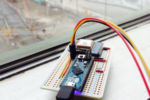
Xed89Github firmware repository: https://github.com/Xed89/BombAlarmFirmware
0%
0%
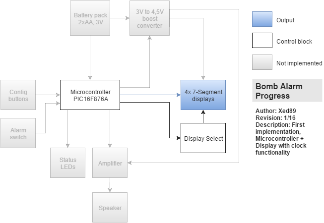
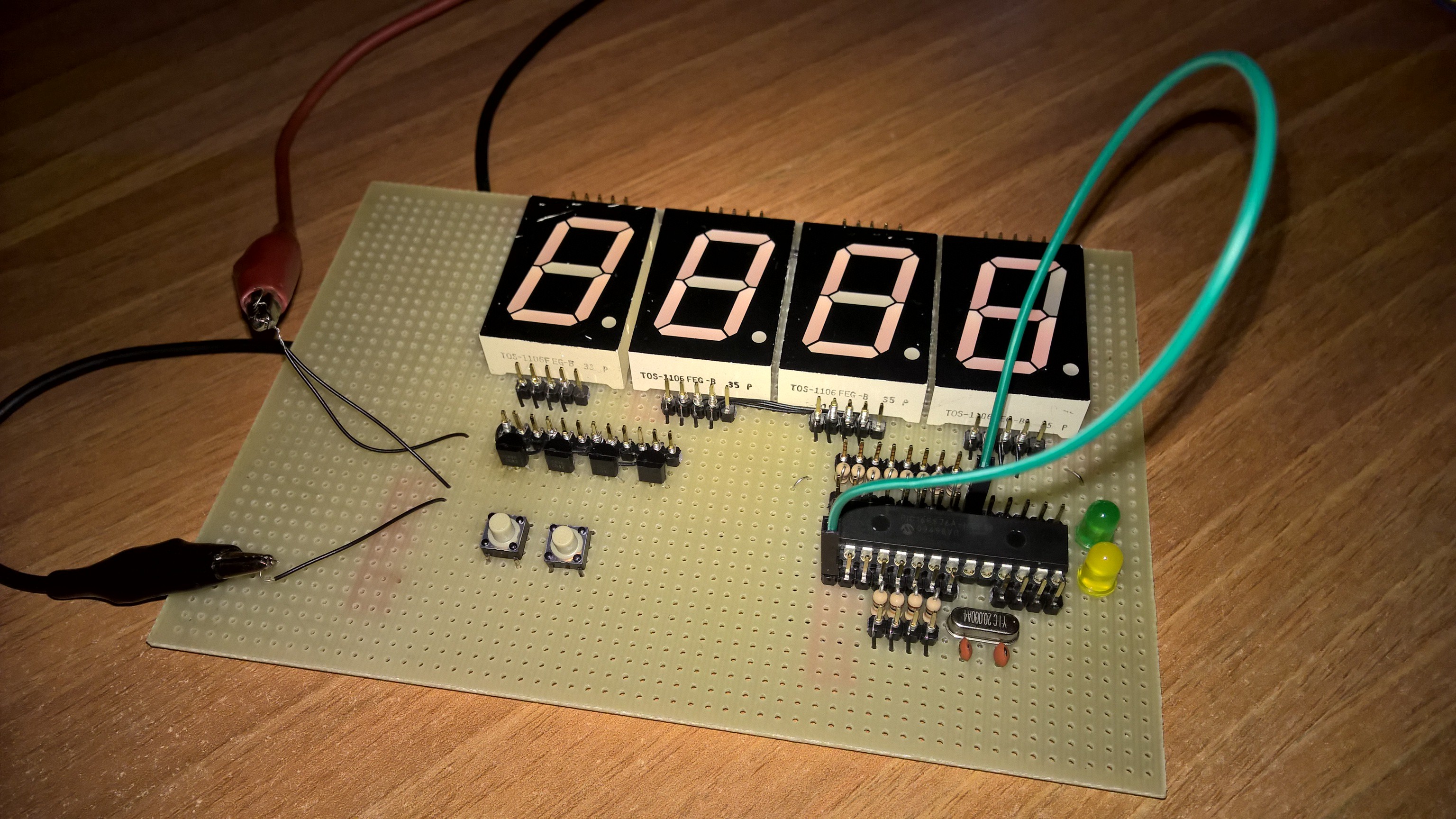
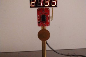
Bomb Alarm
An alarm clock that simulates a bomb, with countdown and beeps.
Become a Hackaday.io member
Already have an account? Log in.
Just one more thing
To make the experience fit your profile, pick a username and tell us what interests you.
Pick an awesome username
hackaday.io/
Your profile's URL: hackaday.io/username. Max 25 alphanumeric characters.
Pick a few interests
Projects that share your interests
People that share your interests
 Pierre-Loup M.
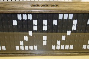
 troy.forster
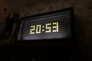
 pauliusbau