 Xed89
Xed89This is the schema implemented so far
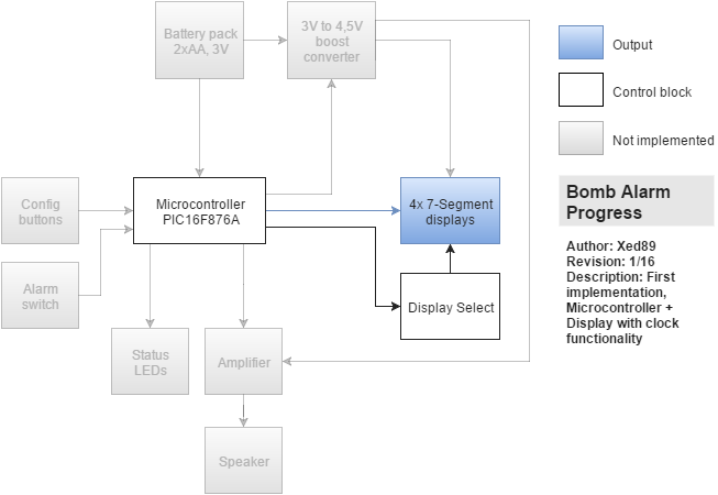
The pic model was chosen because i had it around and it was suitable enough. The processing power is not much a concern but i could not go with a smaller one because of the many pins required for the display (8 segments + 4 display select signals).
Display multiplexing
To be able to drive 4 displays with 8 segments each, i multiplexed them. This allows to reduce the number of pins required to drive the displays to one for each segment, regardless of the display count.
The displays are common-anode, so i used a PNP transistor for each display for the display select block. The PIC cyclically turns on each one of the PNPs and sets the segment signals for that display. It does so faster than the eye can see, so the final effect is that are displays are on at the same time.
Firmware - time base
It uses the Timer1 of the PIC to have a 1 second time base for the clock. The Timer1 is a 16 bit timer, so at 5Mhz clock (1/4 of 20MHz oscillator frequency) with 1:1 prescaler it overflows every 65536/5MHz = 0,0131072 seconds ~= 13msec. There is not a prescaler that makes it add up to a whole number of overflows per seconds, so i used another technique by doing the following at each timer overflow interrupt:
1) Add 65536 to a counter
2) If the counter is more than 5 million, subtract 5 million and signal that one second has passed.
5 million is the number of counts the Timer1 does in a second, at 5Mhz. By subtracting instead of clearing, you allow the leftover counter for the successive second, and never lose ticks behind.
Firmware - clock
For the clock a simple approach has been taken: keep one variable for each digit, plus a boolean for the dot that separates hours from minutes.
1) At each second passed event, increment the seconds (not displayed) and toggle the dot status
2) When seconds reach 60, clear the seconds and increment the minute unit
3) If the minute unit eaches 10, increment the minute tens and clear the units
4) The same with 6 for minute tens, and similarly with hours, altough hours are a bit more complicate, from 0 to ... 23!
The display output is performed cyclically in the main loop of the firmware, and translates each digit (0-9) to the corresponding output segment mapping by using a lookup array, where each entry contains the PORTB bits for that digit.
For example, the digit 0 is 0b00010100, because it has all the segments on, except for the central one (bit 4) and the dot (bit 2).
For some reason, if you turn on the dot together with the hour unit segments, the display dims slightly, so i did it in two separate steps. All the digits have the dot bit at 1 (off), and in the last step if the second is odd, the dot is turned on.
Firmware - bootloader
The firmware was programmed using a bootloader, taken from Microchip application note AN1310 (http://www.microchip.com/wwwAppNotes/AppNotes.aspx?appnote=en546974).
The firmware is taken as-is, but i plan on editing it because it tests for RX pin low to enter bootloader mode, upon startup. Since RX is an input pin, it's floating when not connected, and the PIC enters bootloader mode randomly when you turn it on. I don't want to use a pull-up resistor when the serial is not connected (which i am doing now with a floating wire :P), and since i'll introduce buttons to set the alarm and the clock, i think i'll use those for the bootloader mode, instead of the RX button.
And now... some pics!
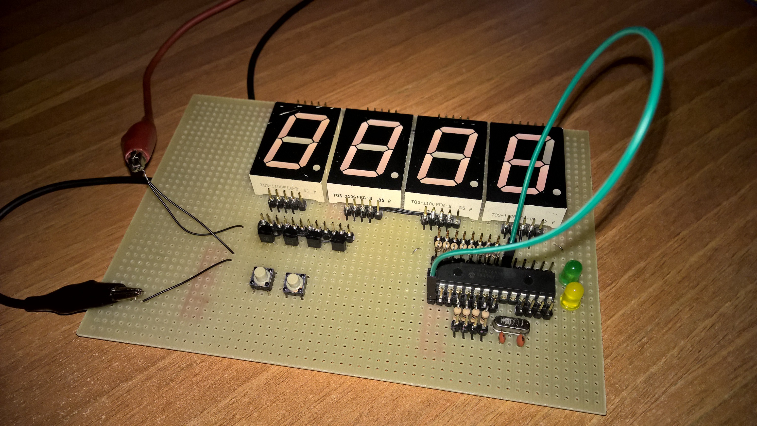
The front side. The buttons and leds are not connected, and yes, that green wire is the one you need to cut for the bomb! (Actually it's the MCLR pull-up i forgot to connect :P)
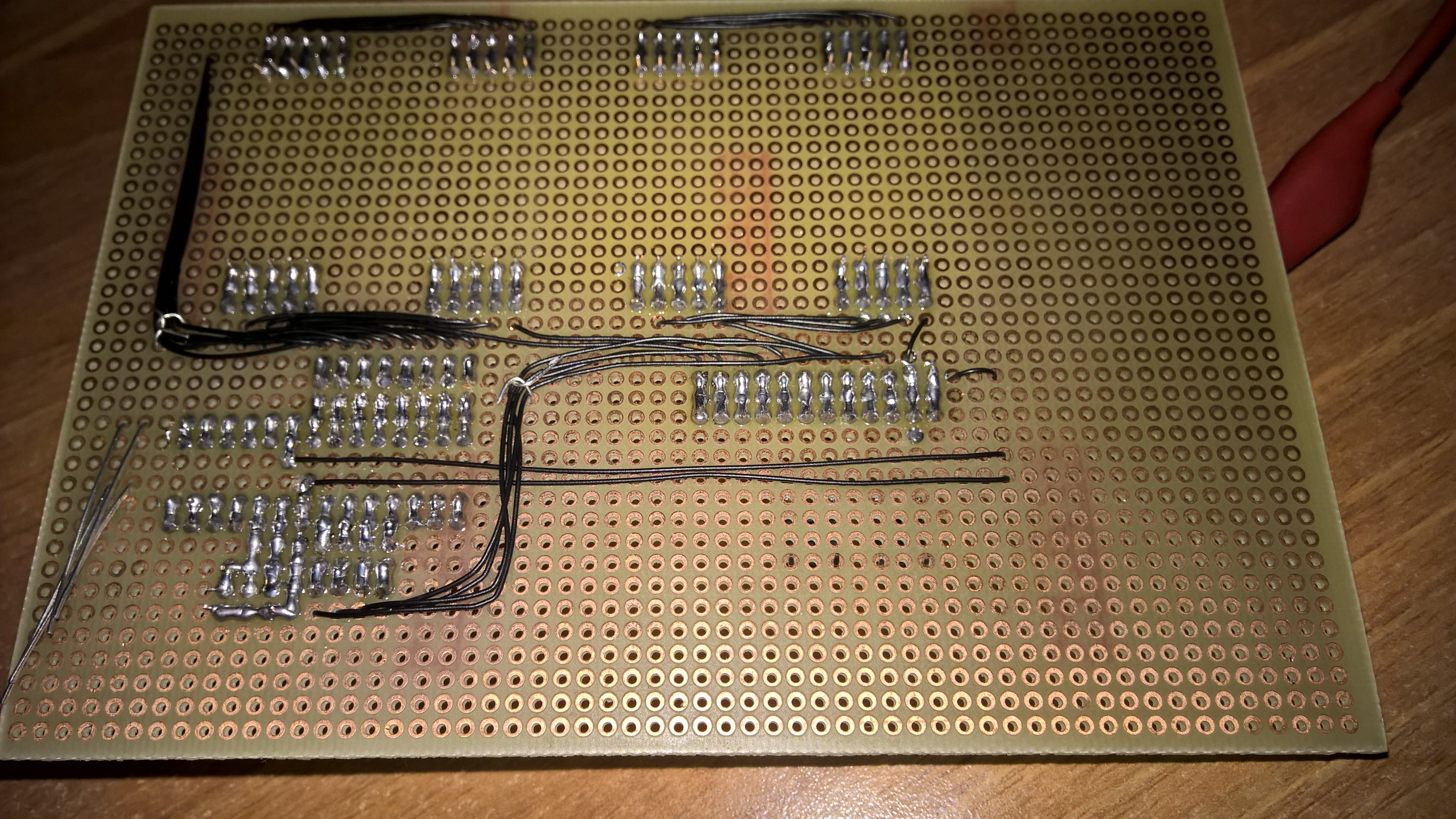
The back side, with awesome soldering and wire-wrapped buses!
See you soon!
This is it for now, i hope i detailed it enough to be of some help for someone who is approaching microcontrollers and wants to follow a simple but meaningful first project :P
Discussions
Become a Hackaday.io Member
Create an account to leave a comment. Already have an account? Log In.