Close
0%
0%

The ERB (Electric Rescue Bike)

An electric motorcycle designed around stringent requirements of weight, power and durability for use in deep woods rescue missions.

Similar projects worth following
2016 - The ERB (Electric Rescue Bike) is now in a second phase of prototyping where I am completely re-imagining the design. Last summer this was a bicycle with pedals and I was wearing the battery in my backpack while I tested the components. I used a beefy downhill bike as the platform and Lightning Rod's 3000w mid-drive kit. In the end I was really unhappy with the kit, which has led me to scrap it and redesign the system from scratch. I've eliminated the bicycle pedals in favor of motorcycle pegs and compacted the whole system - making it all out of aluminum plate and stainless steel. I've upgraded a lot of the parts with my own custom designs. Even the sprocket is a custom design by me in SolidWorks for a specific gear ratio I could not find with off-the-shelf components. Using CamWorks and our CNC mill, I have fabricated the part out of chromoly steel.

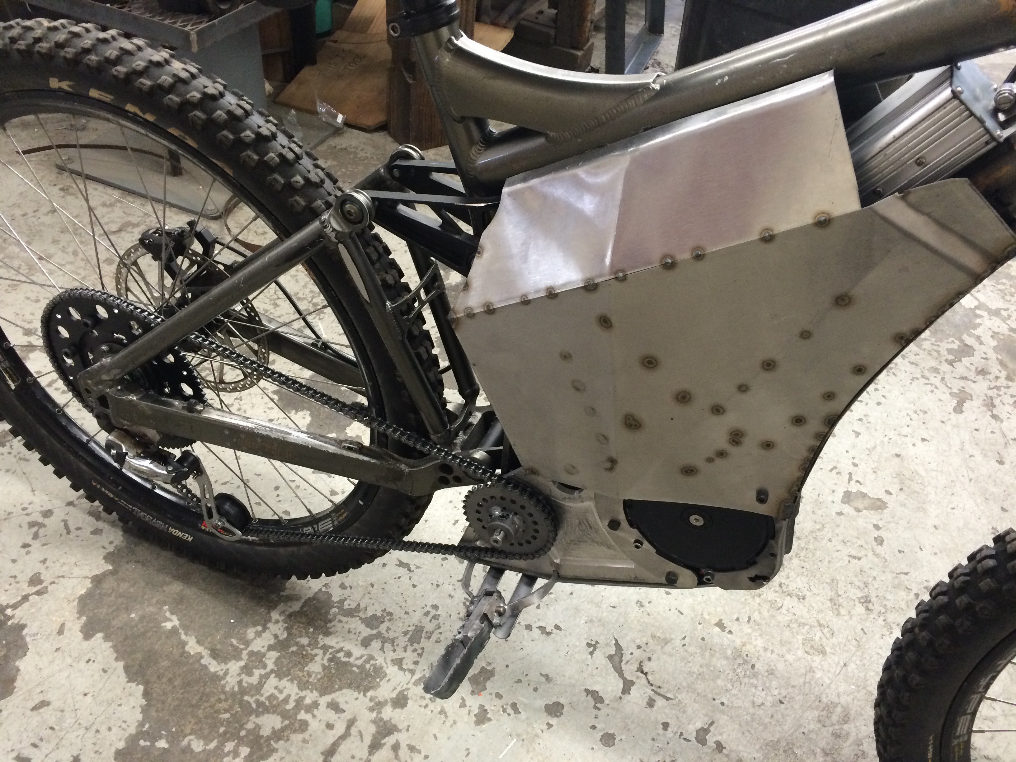
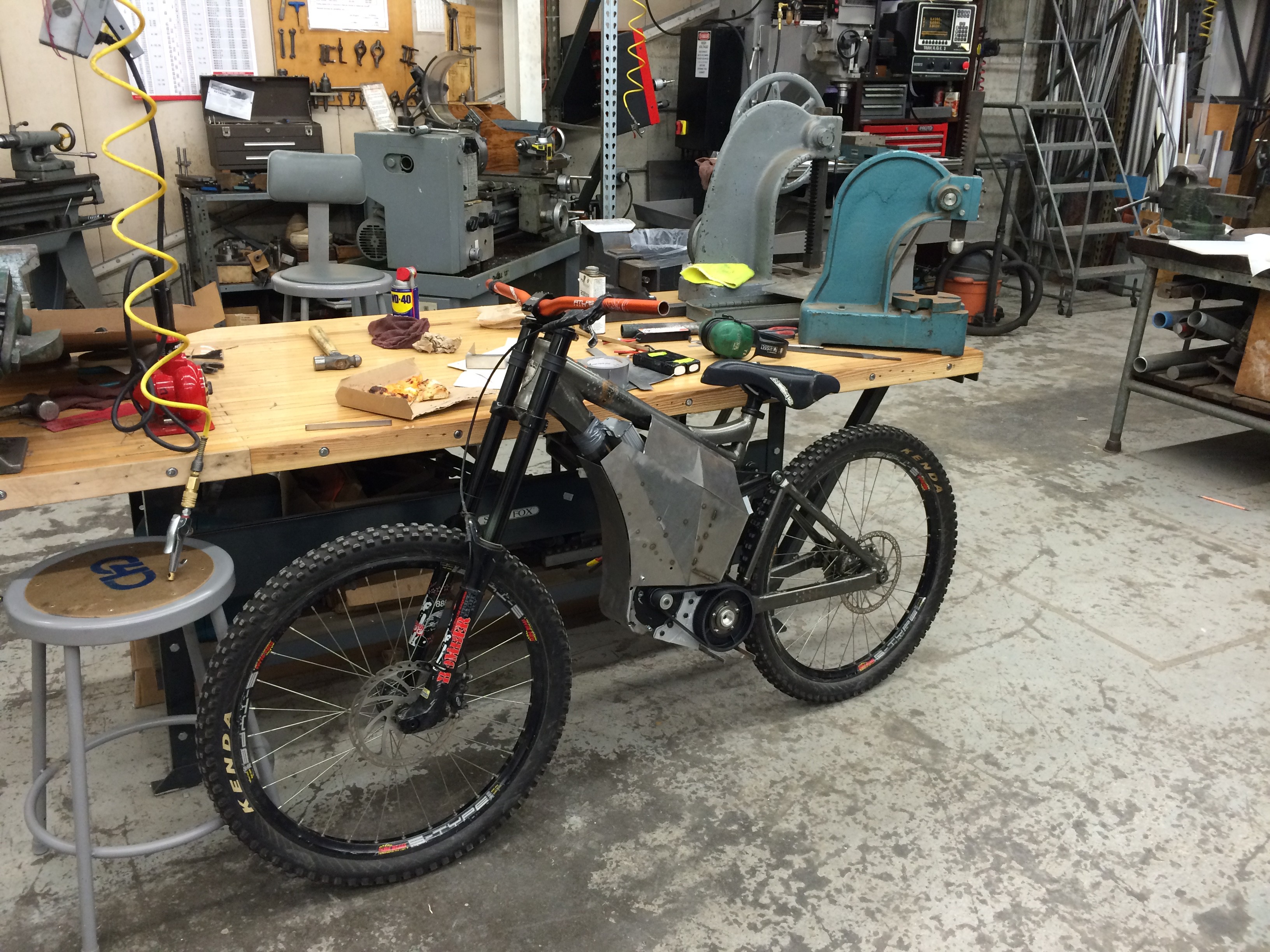
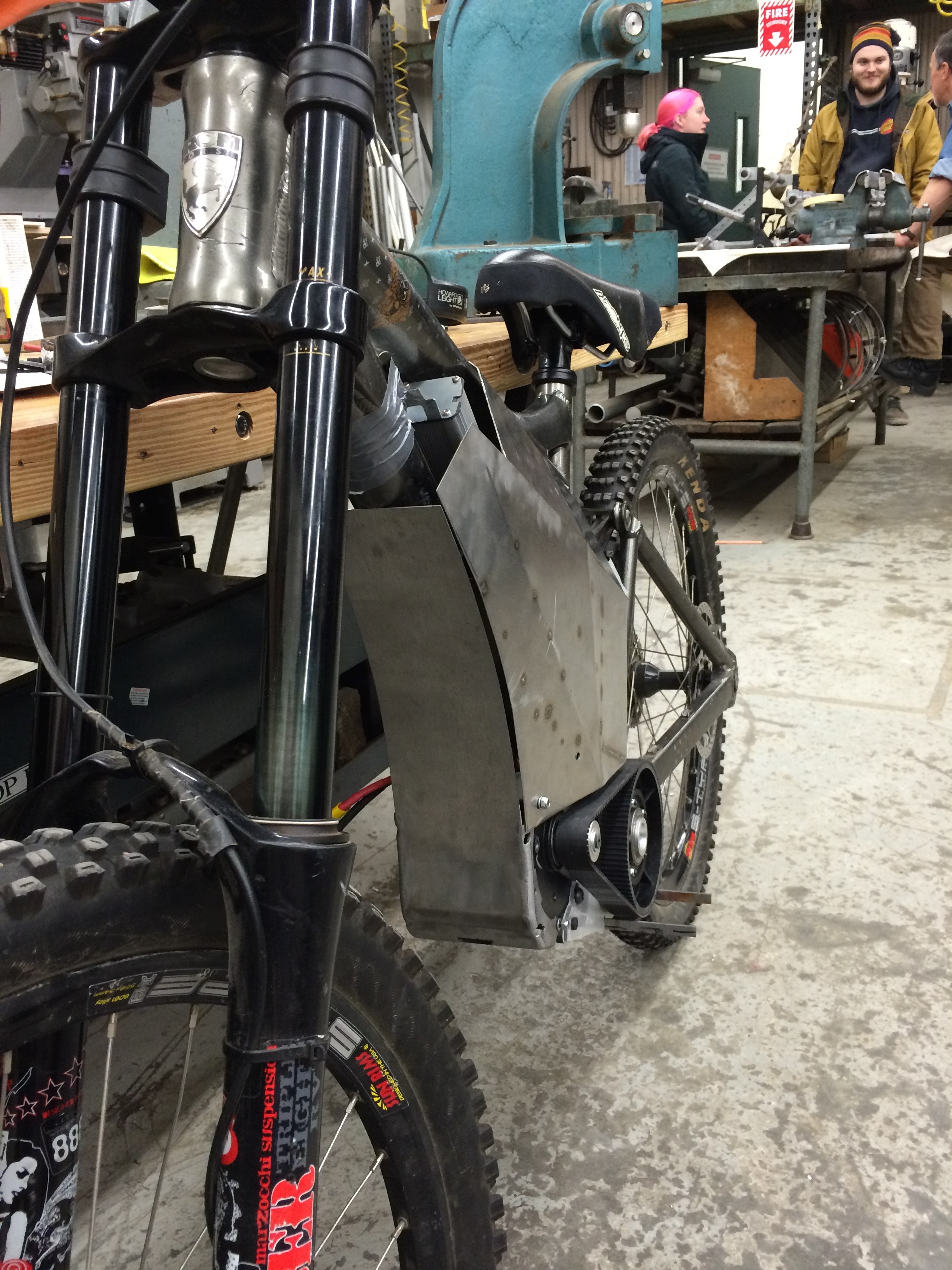
The ERB is a design project at Hampshire College. Based on ideas conceived with members of the Timothy Harkness Fund for Invention, this project is intended to explore the possible benefits of ultra-lightweight EVs in the field of rescue technology.

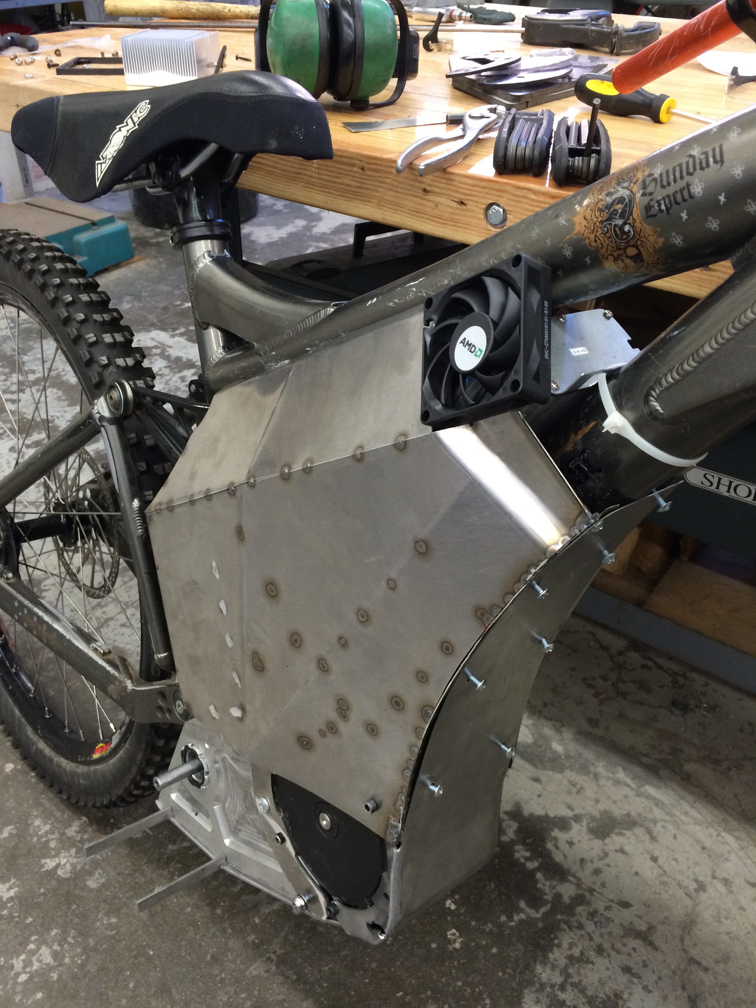
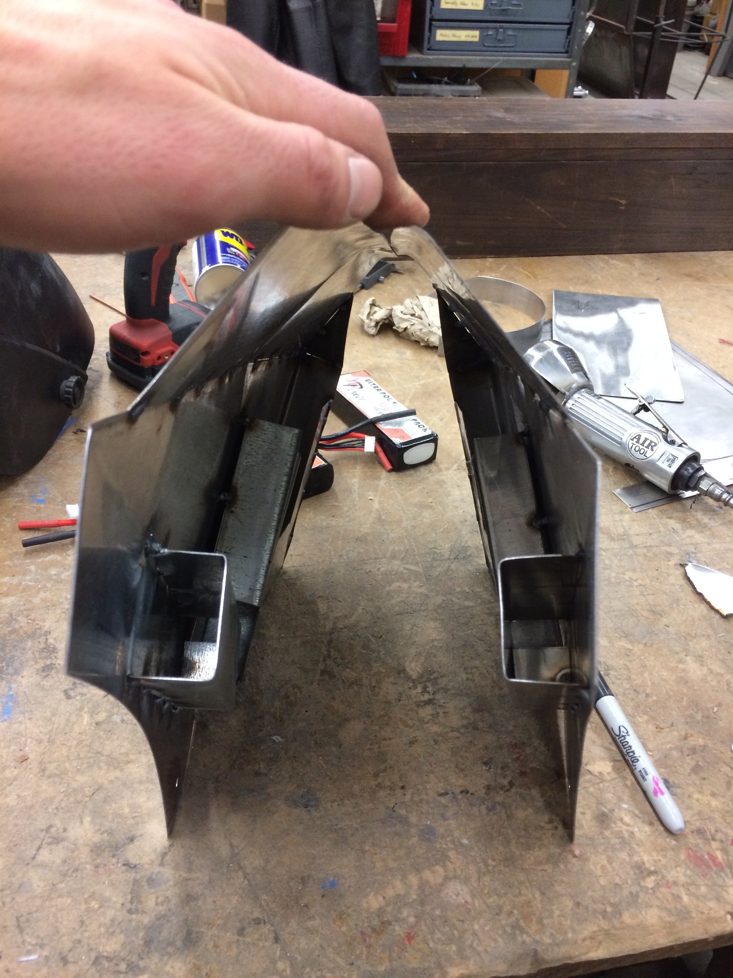
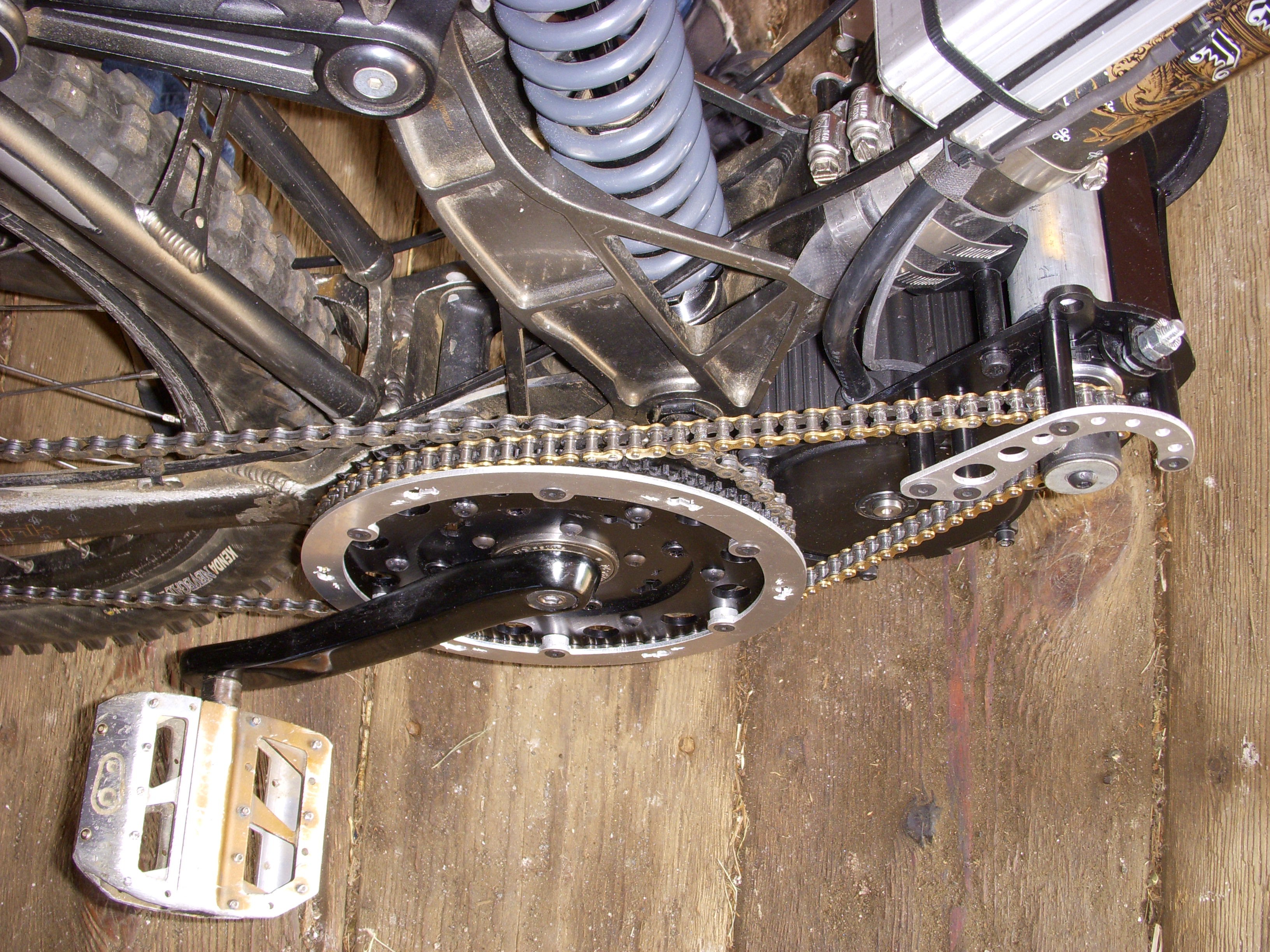
Firstly, this bike is designed to be light and liftable so that first response personnel can get it over large obstacles in the woods.

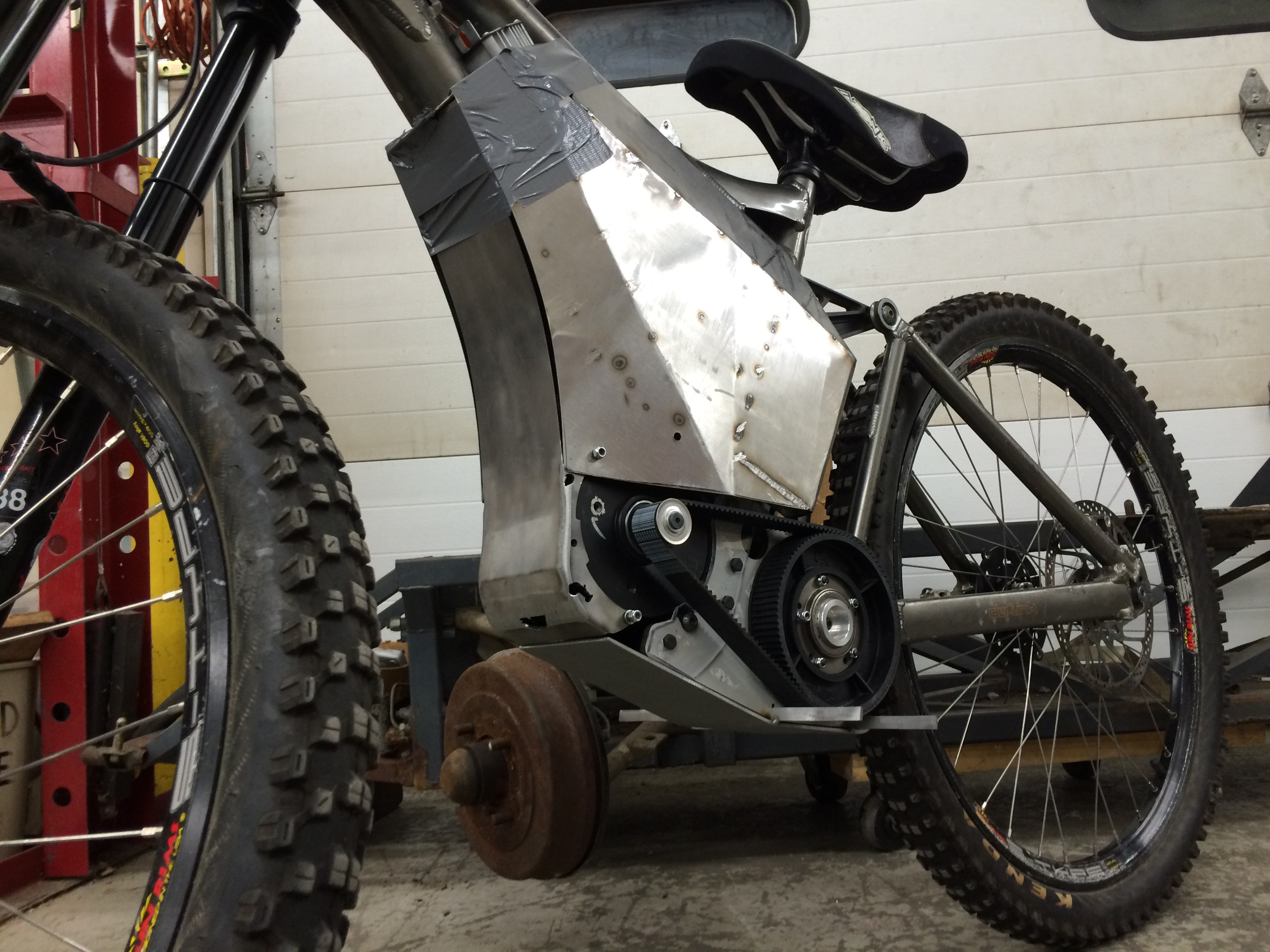
Second, the bike is designed to be powerful and torquey. That's easy, it's electric.

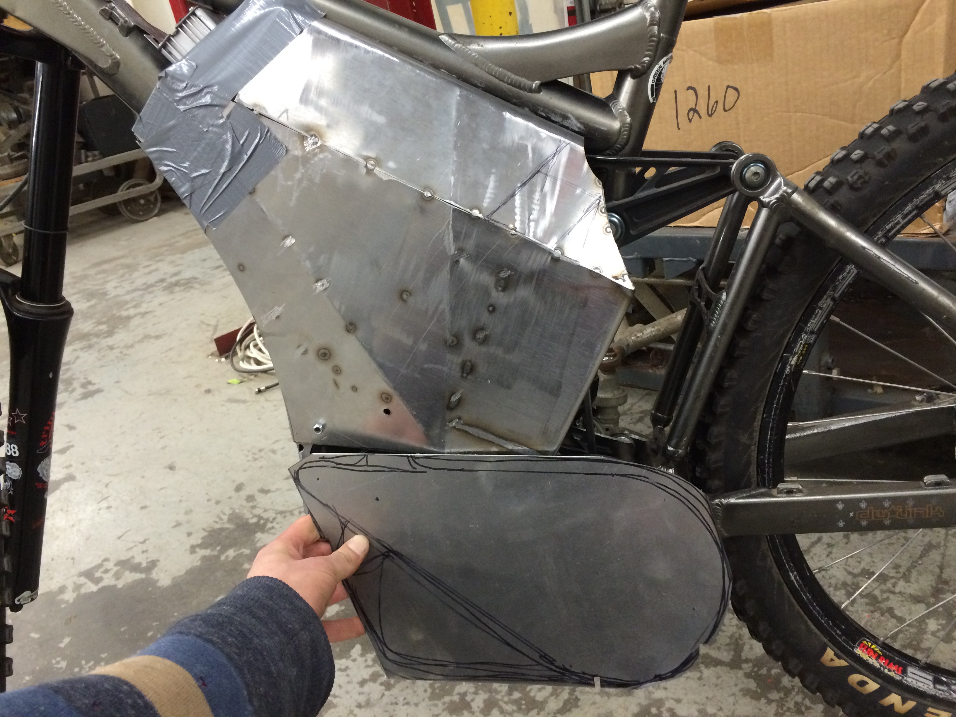
Third, the bike should be completely waterproof. Water proofing electronics isn't that bad, I could even make them submersible because unlike internal combustion engines, they don't need air. This means that the ERB should be capable of ridding through large puddles or even underwater through shallow rivers.

Fourth, the ERB should produce no sparks or sources of ignition. This is easy, the motor is brushless so it makes no sparks. As long as the battery wires aren't disconnected during use, the ERB is not a source of ignition like a gas engine motorcycle would be. That means that the ERB can be used in flammable conditions like ridding through a factory with a gas leak. I don't know if you'd want to do that, but it's good to have options.

JPEG Image - 1.87 MB - 04/12/2016 at 16:10

Preview
Download

JPEG Image - 2.51 MB - 04/12/2016 at 16:10

Preview
Download

JPEG Image - 2.48 MB - 04/12/2016 at 16:10

Preview
Download

JPEG Image - 2.44 MB - 04/12/2016 at 16:10

Preview
Download

JPEG Image - 2.63 MB - 04/12/2016 at 16:10

Preview
Download

View all 115 files

  • 1 × Iron Horse Sunday Frame
  • 1 × Parts from Lightning Rod's mid drive kit
  • 1 × Cycle Analyst
  • 12 × RC car LiPo Batteries
  • 1 × 18 fet Infineon Controller 75v 60a

View all 7 components

  • Still working on the electronics

    Adam Curtis04/12/2016 at 16:14 0 comments

    I ordered a BMS and charger for the 16 series lipo pack that i've created here. I'll post documentation of that mess when I do it. The bike is rideable right now, but to charge it, I have to dismantle the shell and charge each cell individually. For now, here are some pics of the "finished" bike.

  • CNCed sprocket

    Adam Curtis03/22/2016 at 00:41 0 comments

    I milled a 36 tooth sprocket for the ERB and now it goes 30 MPH. Really fun to ride.


  • First test rides

    Adam Curtis03/08/2016 at 03:11 1 comment

    I've gotten all of the electronics wired up and the drive system built too! I've been riding the bike around campus. It pops a wheelie really well, but the gear ratio is 3 times to low. I will be CNC milling a new front sprocket in the next week or so to get my top speed up to 30mph. That will still leave me with LOTS of good torque and a decent top speed as well.

    I still need to fabricate guards for the belt drive and the front sprocket.

    Also I need to buy a charger for a 16 series LiPo battery. Any suggestions?

  • More Sheet Metal

    Adam Curtis02/18/2016 at 04:53 0 comments

    I'm still working on the side plates. These hold the batteries and act as protection for crashes. I have both battery sections done. I just need to finish up the lower sections that cover the gear reduction belt drive and the sprocket on the drive side. After that, and when I know where every bolt and screw is going, I'll machine the 1/4" 6061 Aluminum plate for the motor mounts.

    I still need to make louvers or some kind of vent in these side plates to keep the controller cool.

  • Skid plate, mud guard, fairing

    Adam Curtis02/13/2016 at 23:56 0 comments

    I have the motor mounting plates fully prototyped and the final version is ready for the CNC mill. We have an old converted mill running the A.G.E. 3 system (floppy disk style). These plates will be made of 1/4 inch 6061 aluminum. Under this I'm bolting 1/8 inch chromoly as my skid plate. The mud guard and fairing are made of thin stainless with complex bends for strength. The batteries mount on the inside of the fairing in a set of four. Another four under the other side fairing and another four between the motor mounting plates under the skid plate. These sets will be run in series to achieve 60V.

  • The Bottom Bracket

    Adam Curtis02/11/2016 at 16:00 0 comments

    After removing the pedals from the bike, I thought I would use the bottom bracket to attach the pegs.

    Nope.

    I've simplified and strengthened the whole shebang by running the jackshaft through the bottom bracket. This seems obvious now (luckily) but before I did this all of the power (2.4kW) was forced to pull from this dinky motor kit which is what originally bent all of the steel plates. I'm having a hard time thinking of how to explain this better, but it suffices to say that the whole system is much more ridged and tough now.

    To adapt everything I made several custom parts on the lathe. The chuck was about 17 thousands off so I had fun shimming it every time I did something.

    I made custom bearing sleeves for the bottom bracket so the jackshaft+bearings would fit right.

    Shimming the chuck

    Modifying Lightning Rod's stuff.

    Custom sleeve and bearings in the lefthand thread bottom bracket cup.

  • In the Beginning

    Adam Curtis02/11/2016 at 15:15 0 comments

    This project started in the Spring of 2015 when I won a grant for $2,500 to build a proof of concept electric bike to show the Amherst Fire Department. It really got going that Summer, when I attached the Lightning Rod's mid drive kit to my Iron Horse Sunday downhill bike and wired up some RC car batteries. I road up and down the road in front of my house at 2.4 kW. It was fun but Lighting Rod's kit actually destroyed itself at that power output. The jackshaft bent and the mild-steel structure too. The parts weren't made for the output of the motor (even though the owner, Michael Backus, says it should work at 3 kW.) After months of a headache dealing with him he finally replaced the stainless steel jack-shaft with a chromoly one but he denied the other defects.

    As 2016 rolled around I finally got the jack-shaft back and decided to ditch most of Michael's kit for my custom parts. Since then I have been prototyping in plastics and drawing up designs in Solidworks.

    New connectors for the batteries to facilitate different wiring configurations.

    12 batteries (14.8v 3300mAh 35c) wired 3p 4s to make a 60v battery pack theoretically capable of 350 amps. The controller (18fet Infineon) can only take 60 amps.

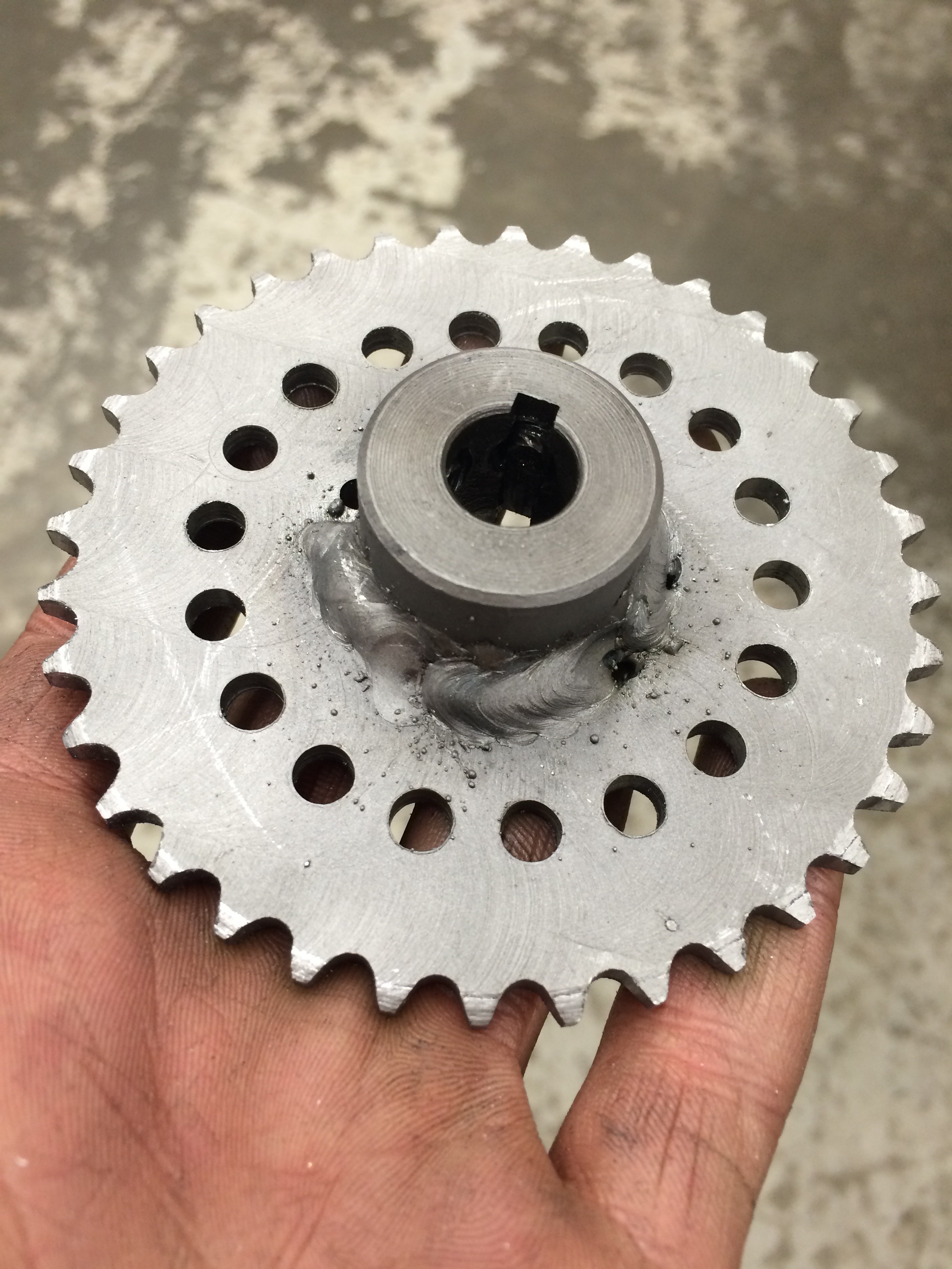
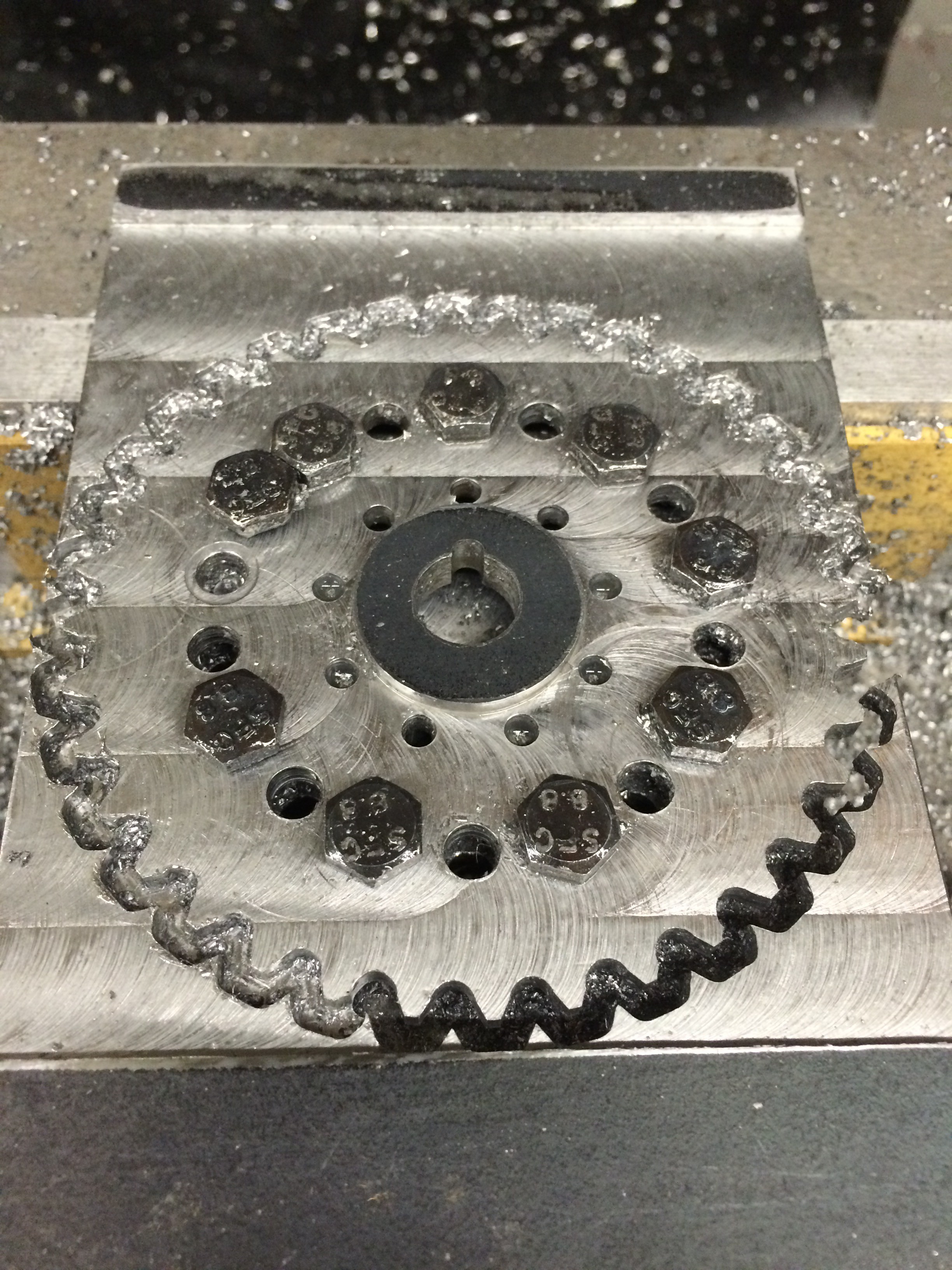
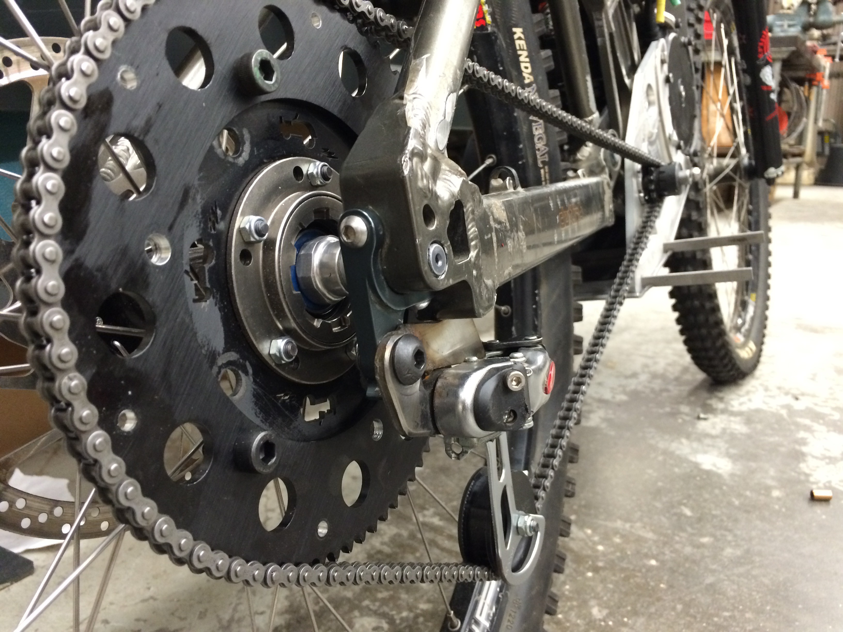
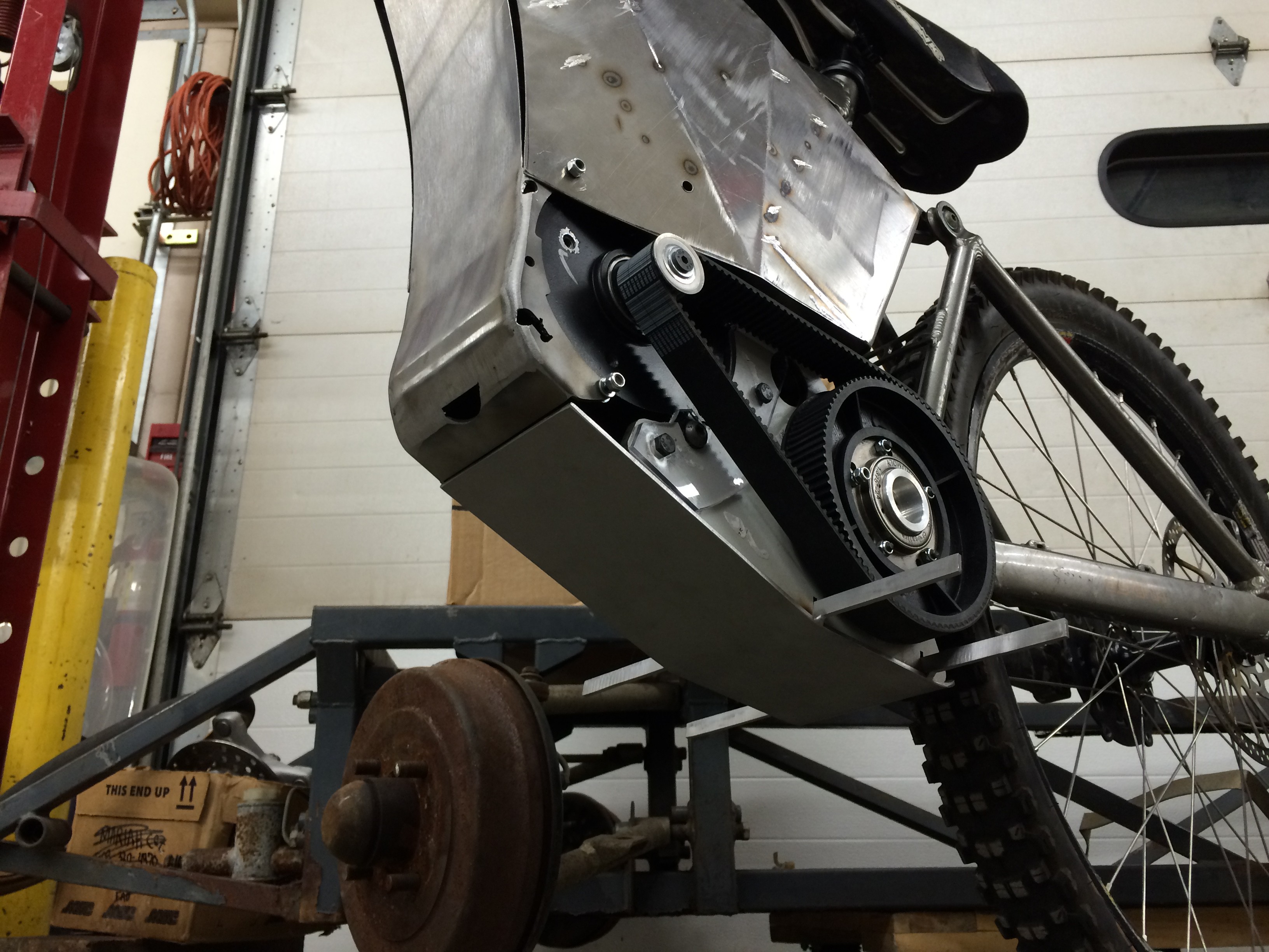
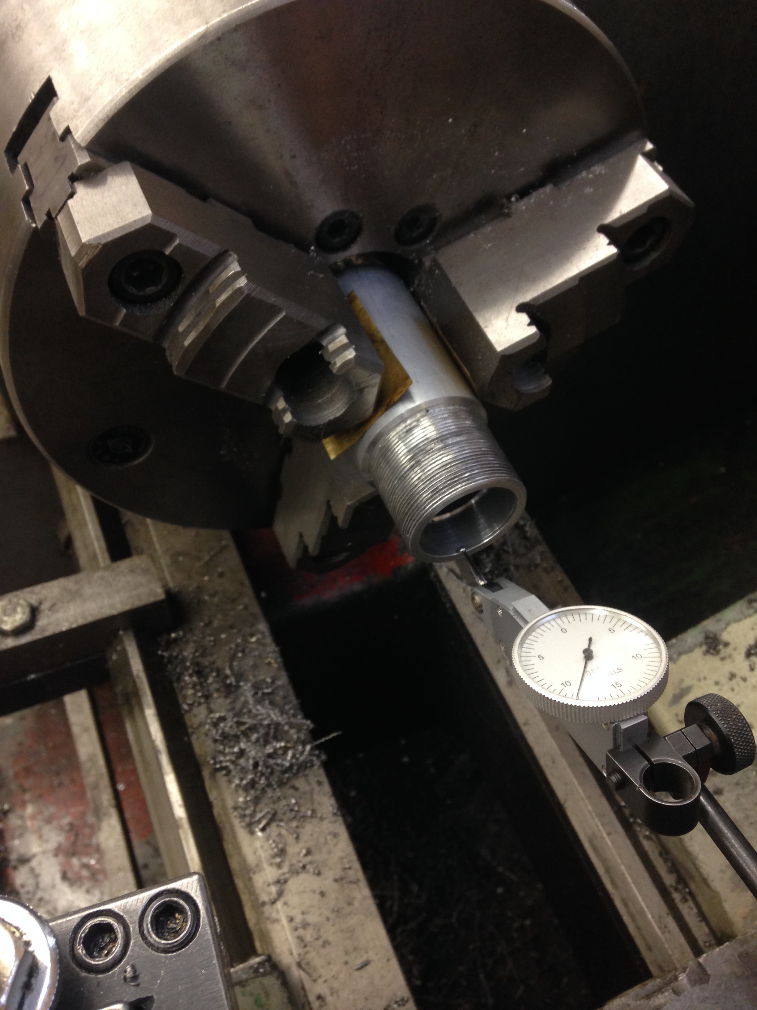
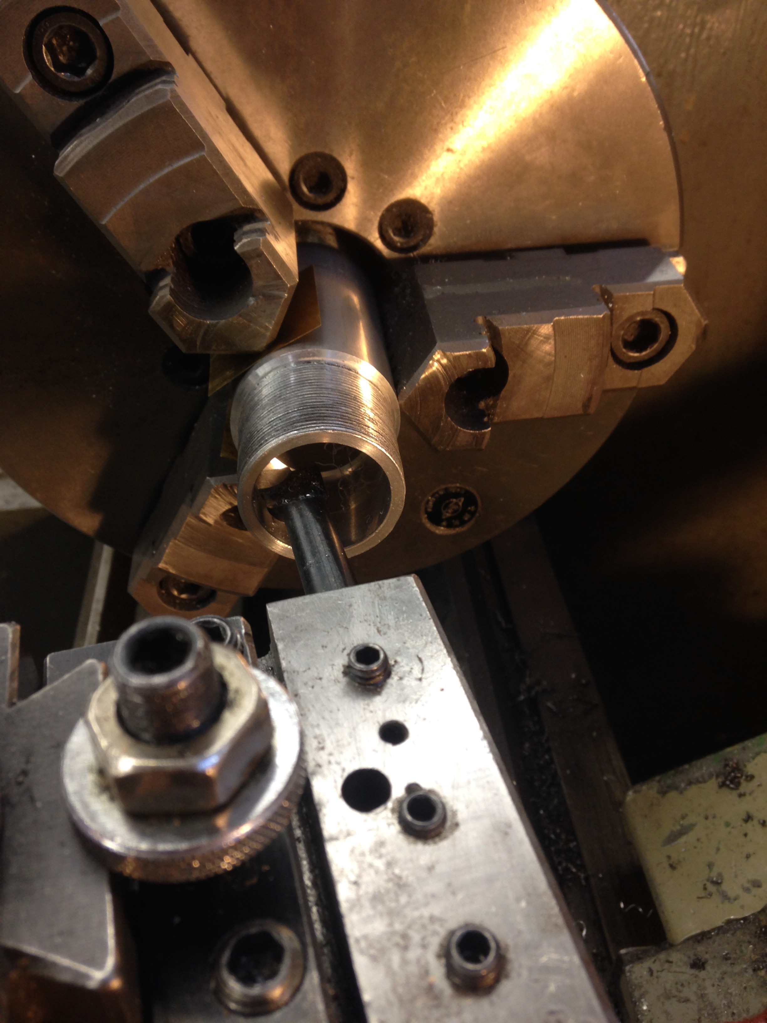
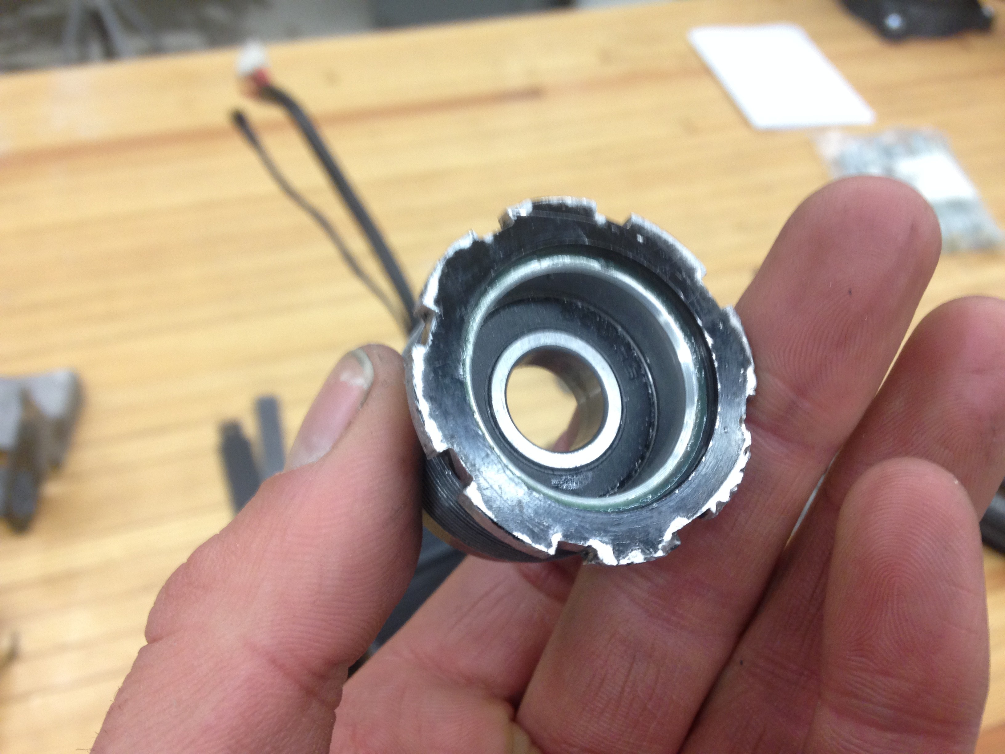
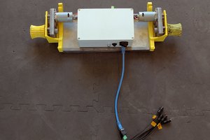
    The original Lightning Rods kit. Looks nice... but when it moves the flaws are immediately apparent. Neither the plastic pulley nor the steel cog were concentric.

View all 7 project logs

Enjoy this project?

Share

Discussions

Dan Twedt wrote 02/04/2020 at 22:16 point

(Just a thought Adam...Since your rescue vehicle overlaps with the "Emergency Communications Universe" that hams are big on, I hope you'll consider participating in the noon hackaday chat tomorrow about keeping Amateur Radio relevant, many new hams are "off-roader" types.--KK6VDR extra class ham and C.E.R.T. trained)

  Are you sure? yes | no

Dan Twedt wrote 02/04/2020 at 08:57 point

Great project! I want three! For more rescue flexibility, an optional aeroshell composed of one third of a BuckyBall (two hexagonal panels with a pentagonal panel at each end) (or towed as a trailer) could combine with two other vehicles so equipped to create a multi-use  "Carbon 60/soccer ball looking" structure/emergency shelter to sleep three on hammocks. (In case overnight rescues or other situations occur.)

  Are you sure? yes | no

Fredrik Högberg wrote 04/18/2018 at 12:14 point

I remember the days when Sam Hill was riding the IronHorse Sunday, what a great era of downhill racing! I love your idea of electrifying this bike, it's very usefull for people like me who live far away from shuttles and lift systems.

If your into OSHW, check out my project  # Lets make OSHW more successful! 

  Are you sure? yes | no

[deleted]

[this comment has been deleted]

Adam Curtis wrote 02/22/2016 at 19:15 point

Thomas,
Thank you for the advice. I really like the idea of fusing each cell. Tesla does that on the level of each 18650 cell in their packs. I will take your advice, thanks for contributing!

  Are you sure? yes | no

Similar Projects

Does this project spark your interest?

Become a member to follow this project and never miss any updates