 sidsingh
Many times I needed a small and handy continuity tester for those hard to reach places and especially working on car or out on the road. Multimeters are big and heavy to lug around and cannot fit in pant pocket. Cheap continuity testers on ebay can be had for few bucks, but where is the fun in that! I was browsing through hackaday.io for similar projects and came across Jose Ignacio Romero's continuity tester. I instantly liked his build, but do not have the PIC controller he used.
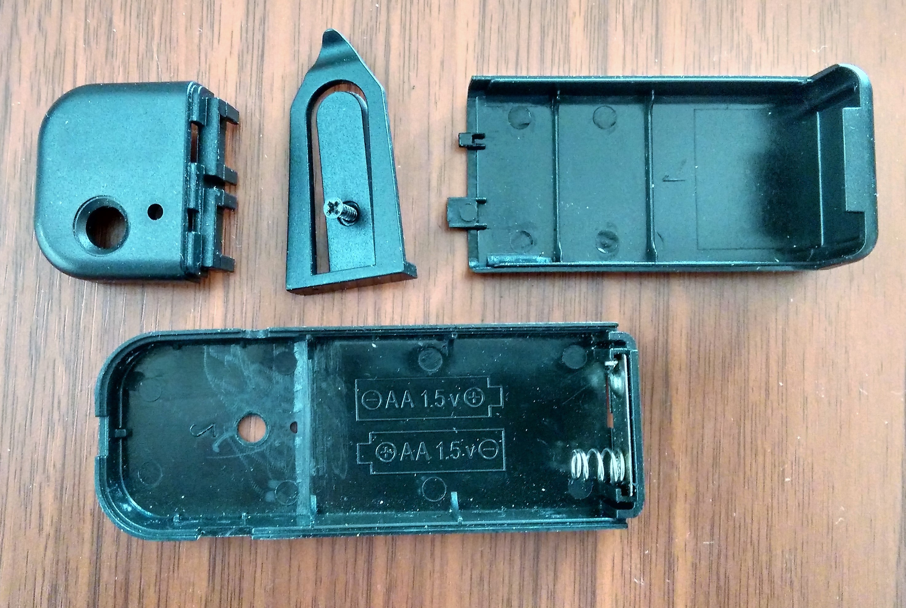
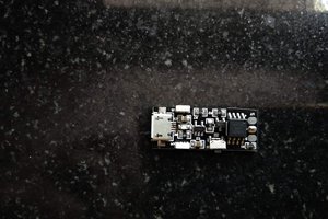
I wanted to build this project entirely out of components available in my parts bin. I have few PIC10LF322 lying around , they are small (6 pin SOT23), run at 16MHz, 512 bytes of Flash, packed with ADCs, PWMs and perfectly suited for battery powered small applications like this. I also happen to have a nice case for this project salvaged from an EL wire inverter from a previous project. The case is small and sturdy, with cutouts for LED, push button and wires. I had desoldered tact switch and battery contacts from EL wire inverter PCB, which came in handy for this project.
PIC 10LF322 has 4 IO ports and one of them is a digital input only. That leaves me with only three ports to play with. The input only port (RA3) is dedicated to read push button.

I had written few experimental example codes for 10LF322 many moons ago using MPLAB v8.92 with HiTech C compiler. I used the same IDE setup for this project and reused many old snippets. One of the major issue working with low pin count controller is the ability to debug. Connecting a display is out of question. I temporarily used one of the pins to spit out bit- banged serial data to my PC primarily to know what the ADCs are reading. Implementing continuity and diode test was easy.
I needed a handy way to test LEDs also in the same device. Most white and blue LEDs wont fire up below 3V. The design has a 10Khz PWM boost converter with feedback to regulate output at 4V while testing LEDs. With the addition of boost converter, I ended up using a bit more components than I intended for this project. All components are common and not critical and can be easily substituted with any other equivalent part. (except R3, R5 and R7, change in their value will directly affect ADC readouts).
Circuit Operation:
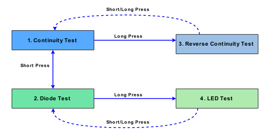
The push button cycles between two commonly used modes Continuity test and Diode test. Other modes are activated using long press.
Continuity and Diode Test Mode
RA0 (PWM) is shut down, RA1 is ADC input and RA2 is buzzer and LED output. ADC reads the voltage divider created between R5 and probe tips. If the resistance between probes is low enough the LED and buzzer sounds. ADC sample should not be taken while LED/Buzzer is on, as the probe tip receives additional voltage through boost converter feedback resistor R7. By determining what the ADC reads in respective modes, suitable output is generated using LED and buzzer.
*see ADC readings.xlsx spreadsheet in files section.
LED Test Mode
RA0 (PWM) is turned on. RA2 LED/Buzzer is ADC input and RA1 is output and grounded to create a feedback voltage divider between R7 and R3. A 3.3V zener diode is used inline with schokkty to restrict VDD to leak into Probe+ via L1 and D3 during Continuity and Diode test mode. PWM to base of Q1(NPN) creates higher voltage across output capacitor C5 and the same is fed back to ADC using R7 to regulate pulse width to keep output under 4V.
The microcontroller goes into sleep if there is no activity for 3 minutes.
Power consumption (VBat = 2.9V)
Sleep mode = 170uA
Continuity and diode test idle = 1mA
Continuity and diode test LED and Buzzer ON = 13mA
LED test idle (no LED connected) = 7mA
LED test with LED connected = 15-18mA...
 DailyDIY
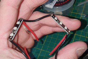
 LouD
LouD
 Tyler Gerritsen