 Jerry Biehler
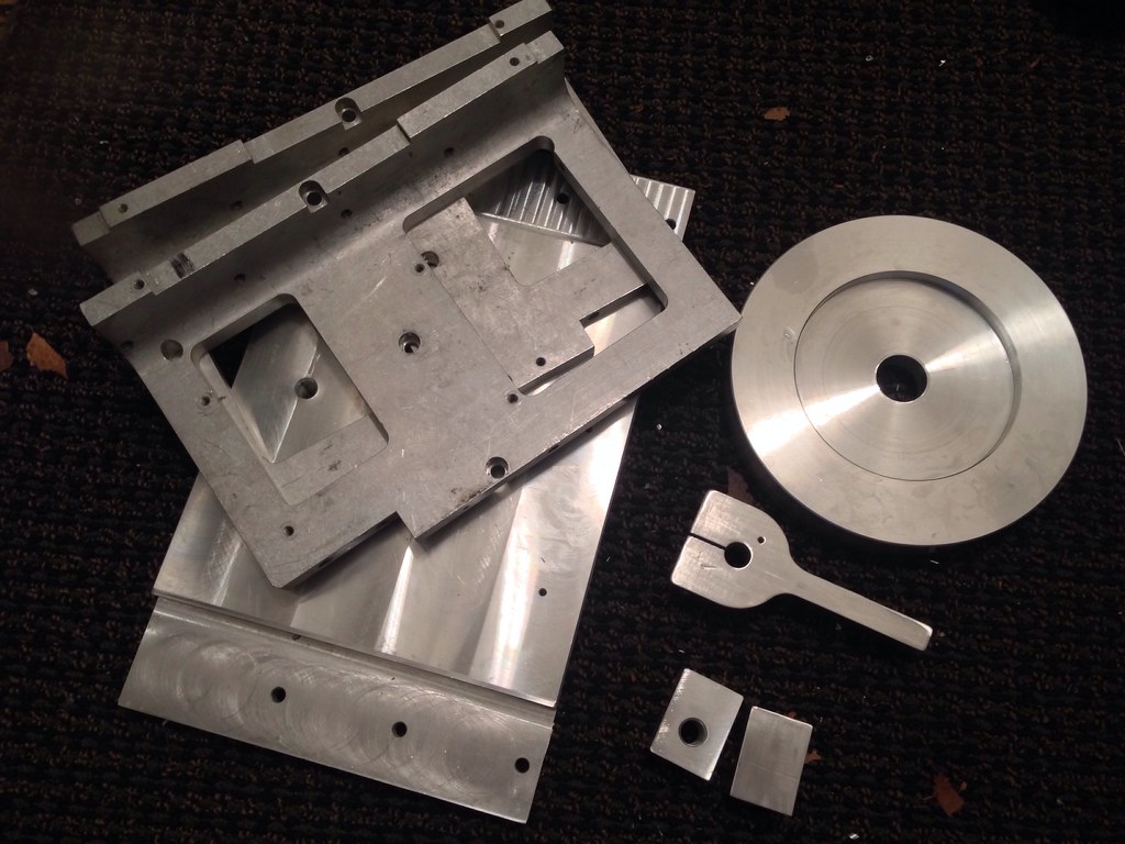
So I figured it is time to build one myself. Probably 10 years ago I picked up an old PRI robot that had come out of intel or something, I think it had moved around wafer boat or something. Took most of it apart, gave the steppers away, and kept the useful stuff. Bunch of linear slides and stuff. The one gem was the big harmonic drive that the robot rotated on. The OD on the driven disc is 10" in diameter and it is supported by a nice, large ~8" bearing under it. All made out of aluminum so it is still reasonably light. This is going to be my Right Ascension (RA) drive.
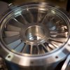
Harmonic drives are very cool, they use a flexible spline on an eccentric bearing that wobbles inside another spline with a couple more teeth than the flexible one. Since there is alway hard contact between the flex spline and the outer splice the drive is truly zero backlash. They are used in a lot of places like robots, cnc and even the moon rover. It used one harmonic gear in each wheel. Here is a video of the one I am using, you can see the flexing of the spline. This is 102:1 gear ratio.
https://www.youtube.com/watch?v=02jxx2sjaXs
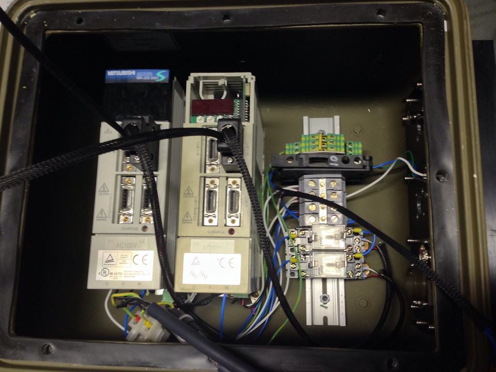
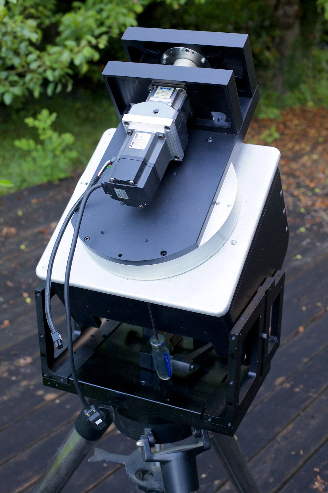
I have since taken it apart and cleaned it out, it runs much smoother now. The drive had a DC servo on it with a 500 count encoder. I tried setting it up with one of my little Elmo Harmonica servo drives like what I used with the laser cutter but it would just not tune. I dont thing the drive could supply enough current. Also after doing the calculations I found 500 lines is just not enough, that is less resolution than the mount I am already using. After messing around with various combinations of servos and gearboxes to drive it I have settled on a Mitsubishi MR-J2 200W brushless servo with a Bayside 10:1 gearbox. This drives the harmonic drive and gives me a resolution of 8,355,840 steps per rev. This puts me way above useful resolution.
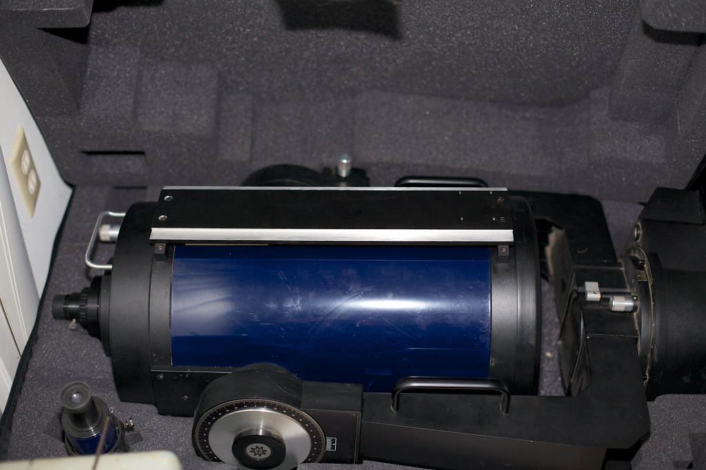
For the Declination (Dec) drive I am using another Mitsubishi 200W servo, this one is a MR-J2S series with a 131,072 count encoder. This will drive another Bayside gearbox, this one 3:1 and then that will drive a 80:1 harmonic drive which will have the saddle for the telescope on it. This gives me stupidly high resolution of 31,457,280 steps per rev. I may try direct driving the harmonic drive bypassing the 3:1 gearbox, I am pretty sure it will have enough torque. The OTA is adjusted on the dovetail mount to balance it.
The Dec harmonic drive is pretty neat, it is basically a cross roller slewing bearing with a harmonic drive built in. I think these were pulled out of SCARA robots, I got one from S. Korea shipped for $180. More than I would have like to pay, but oh well. Considering I have had all the rest of the parts lying around I cant complain too much!
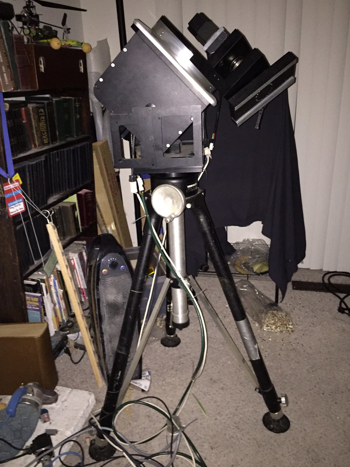
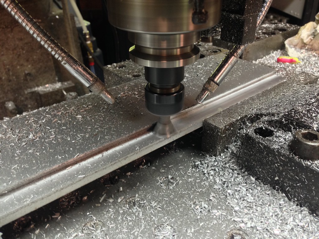
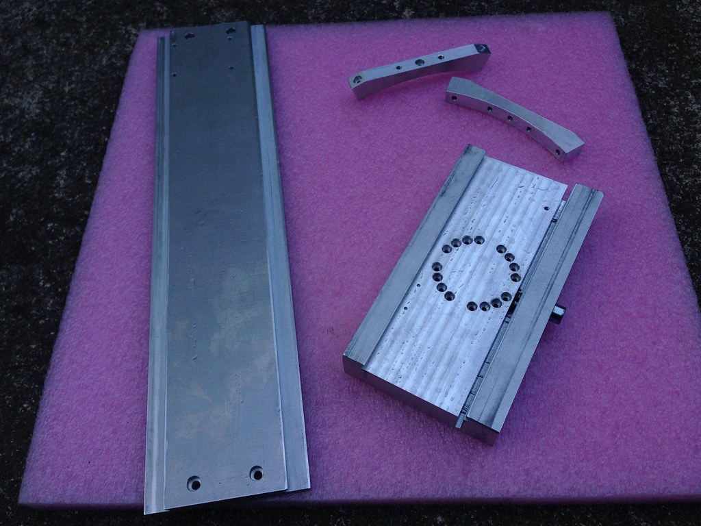
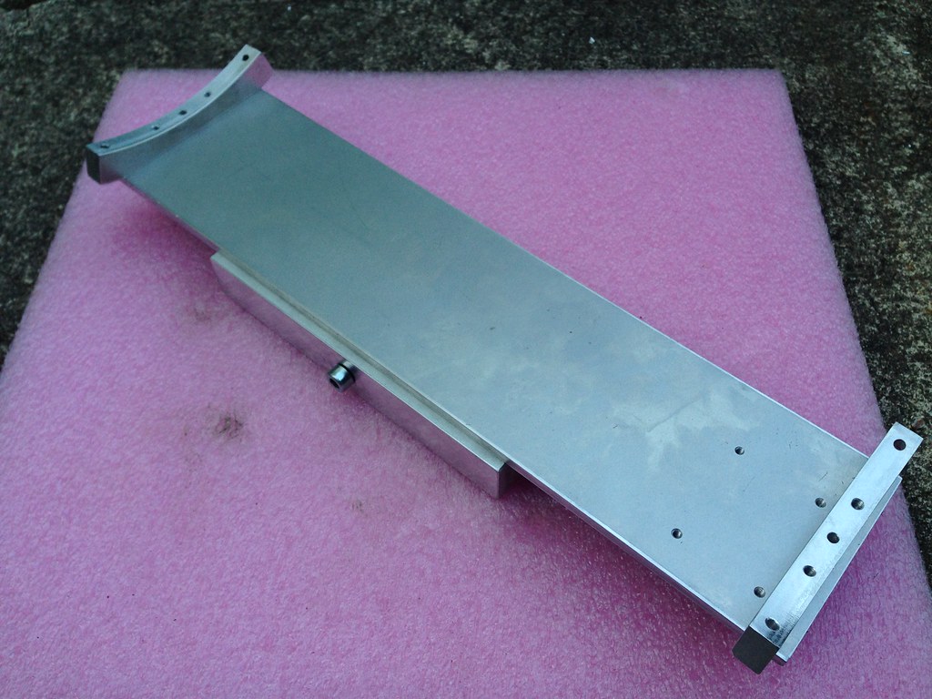
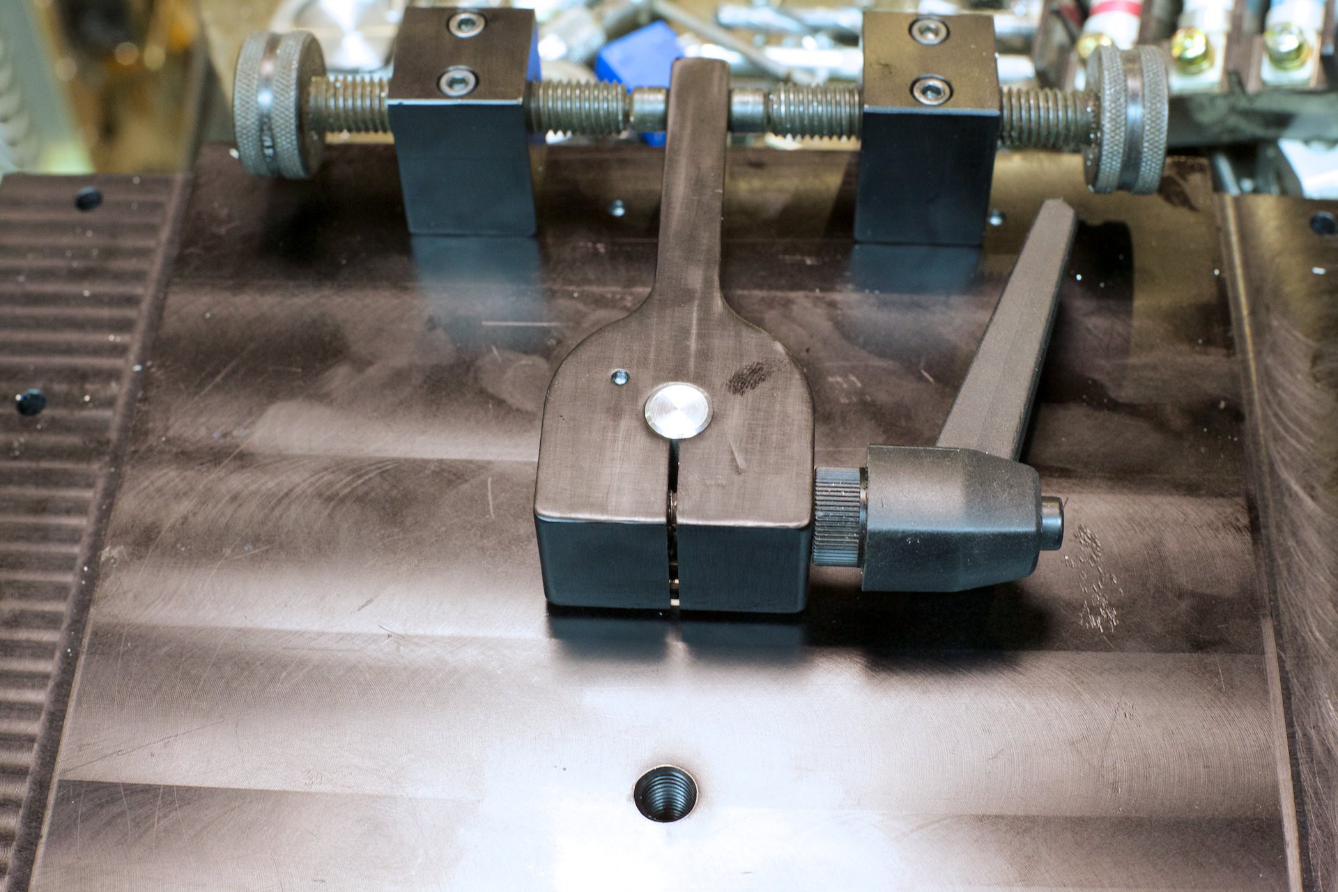
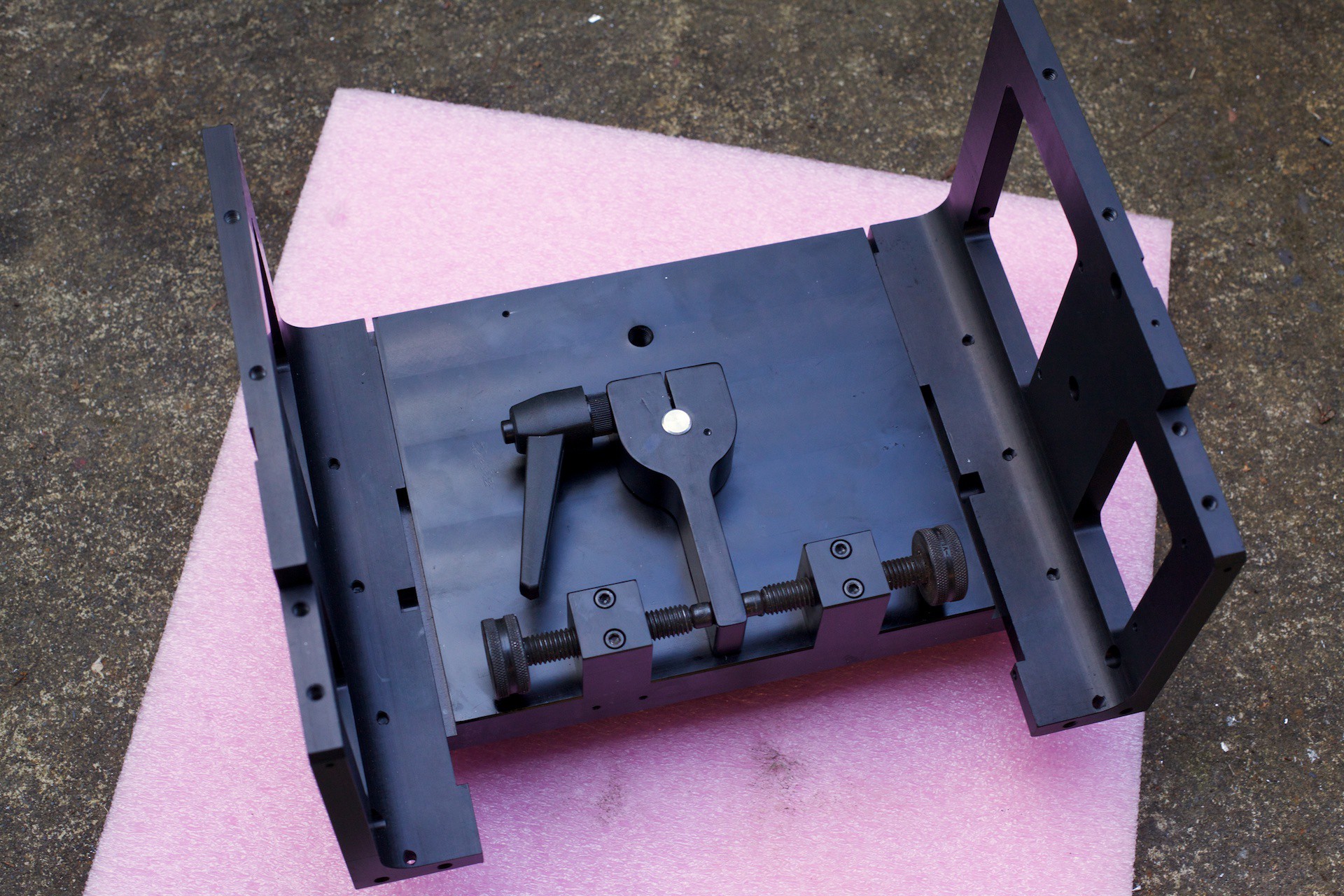
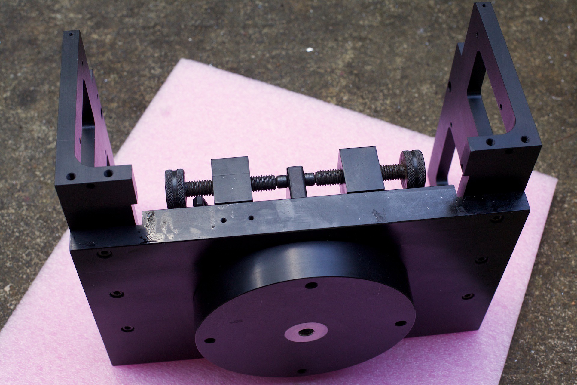
Im now drawing up the design for the tilt mechanism for setting the angle of the RA drive and figuring out how I am building the motor mount for the Dec drive.
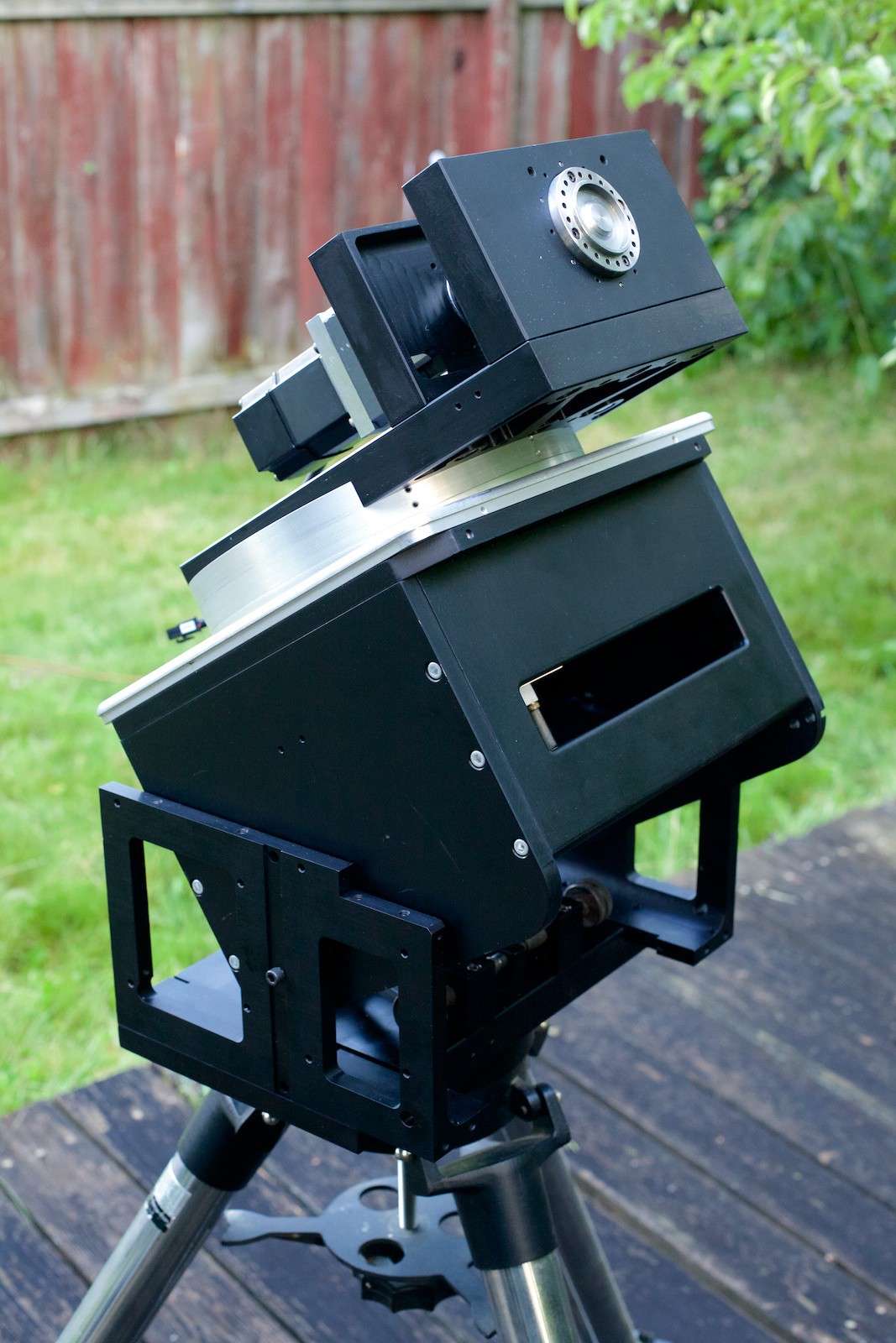
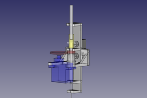
This is the back of the main harmonic drive with a servo and the gearbox attached. There are commercial GEM setups available but they start around $20k!


 charliex
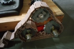
 Michael Mayer
 Ossum
Ossum
Very expensive steup;