 esben rossel
Driving the TCD1304:
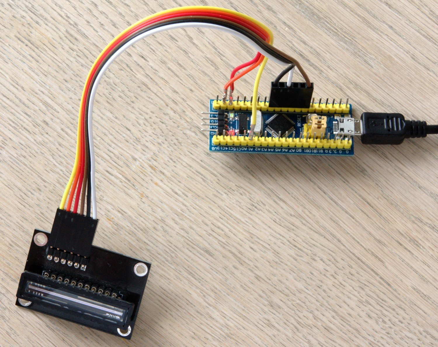
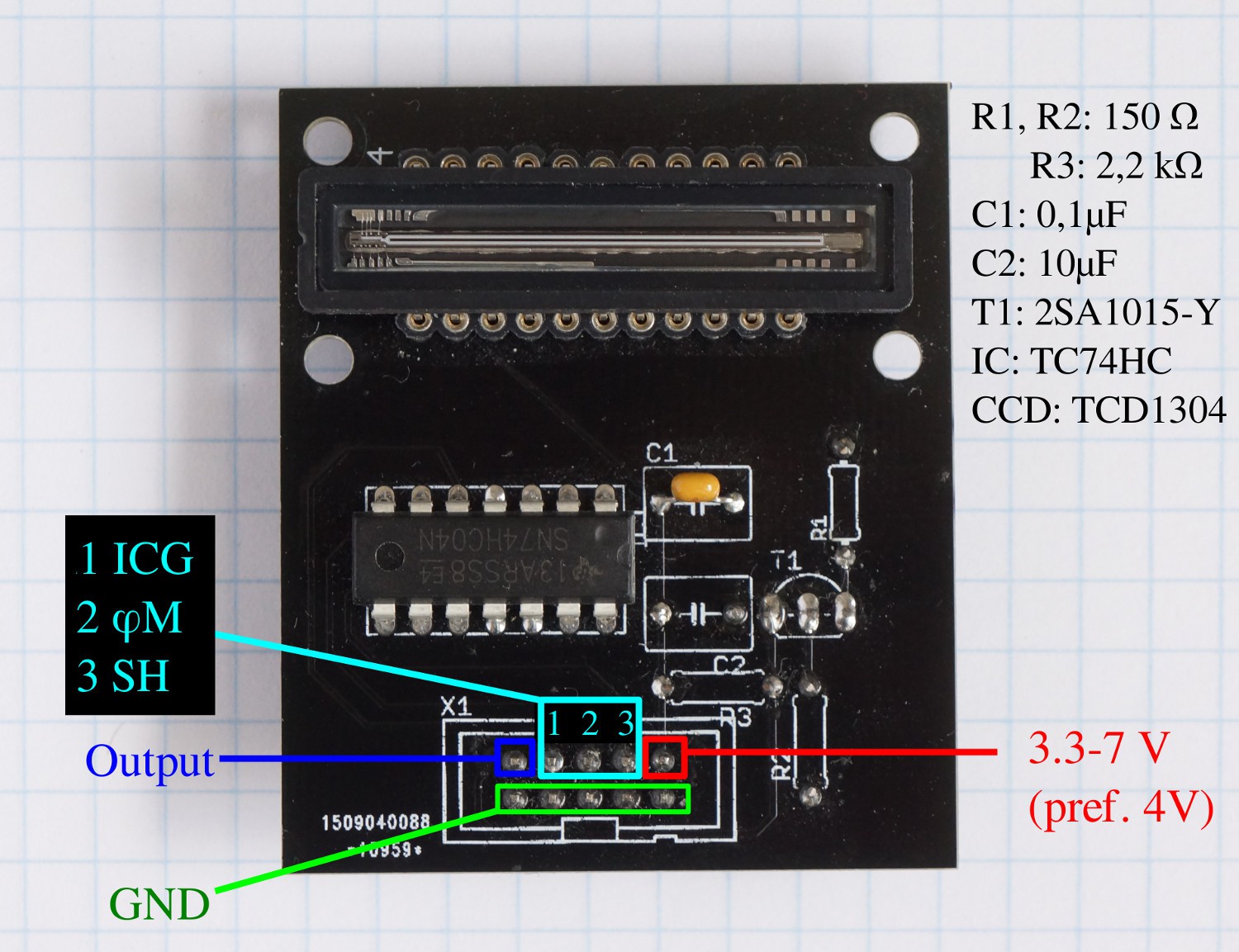
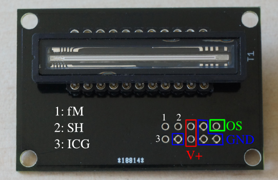
The TCD1304 requires the following input to function
- The master clock (fM)
- The shift gate (SH)
- The integration clear gate (ICG)
The frequency of fM must be in the 0.8-4 MHz range. In this project fM = 2.0 MHz (but it is user changeable)
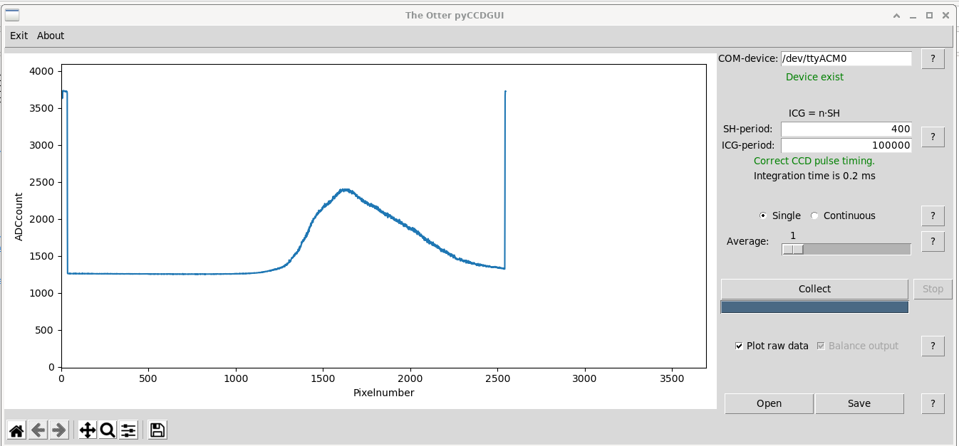
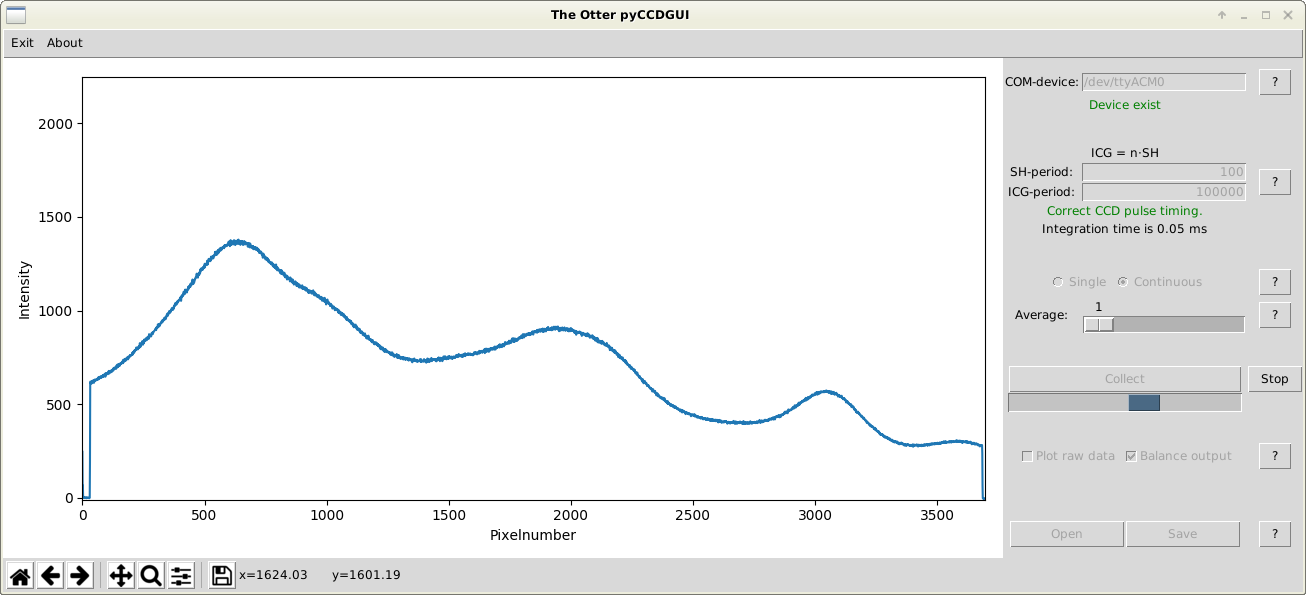
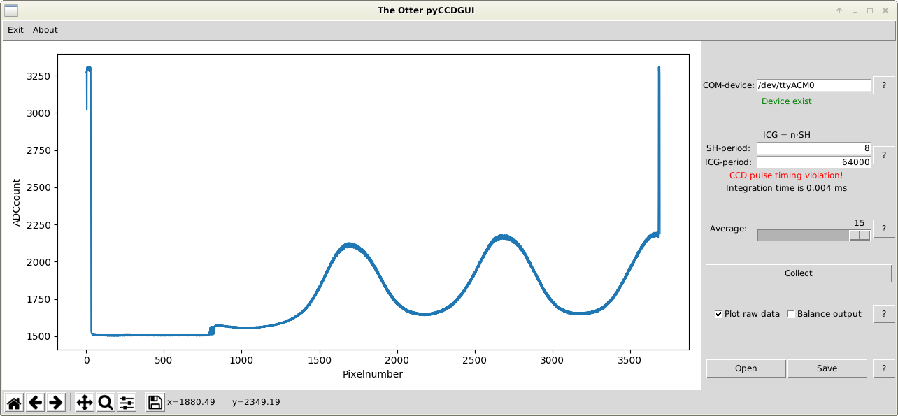
The SH-period defines the integration time. The ICG-pulse defines the moment the pixels are moved to the shift register.
The datasheet provides the following figure for the timing requirements for the SH and ICG pulses:
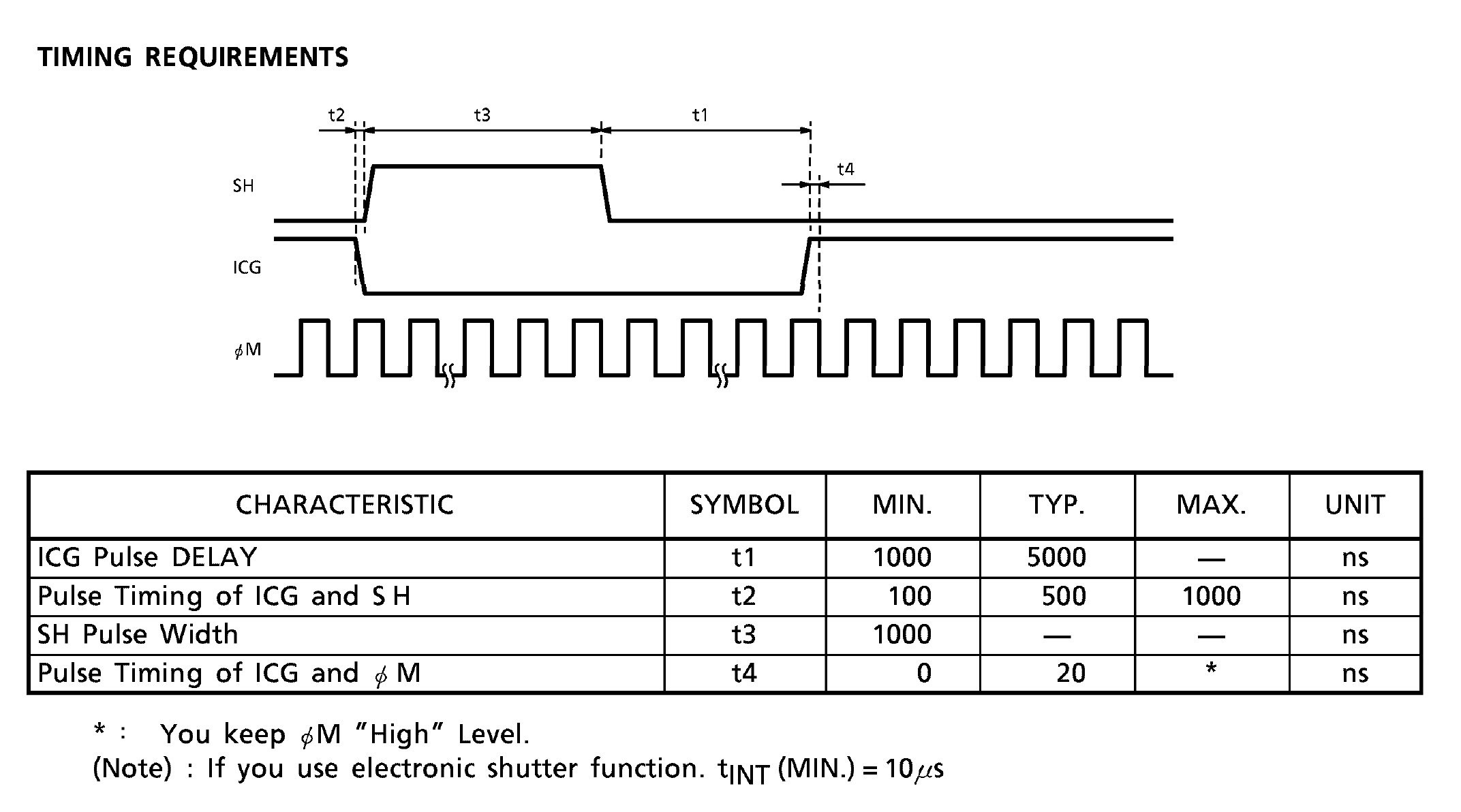
This translates to the following:
- SH must go high with a delay (t2) of between 100 and 1000 ns after ICG goes low.
- SH must stay high for (t3) a minium of 1000 ns.
- ICG must go high with a delay (t1) of minimum 1000 ns after SH goes low.
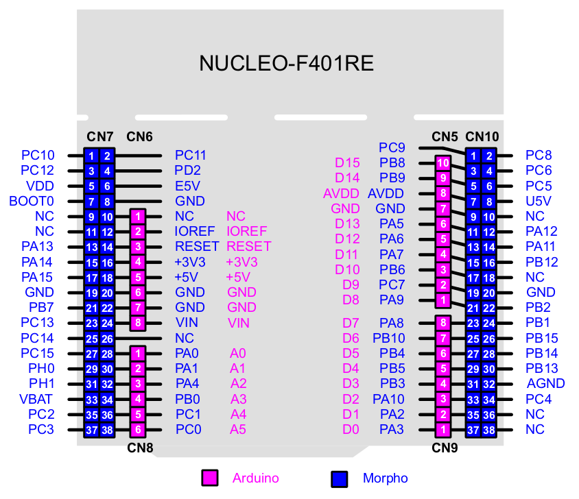
This is all taken care of by the timers in the STM32F401RE. In fact once they're set up the MCU is not doing any work. The only thing the user has to do is to choose ICG-periods that are multiples of the SH-period.
Since the timers controlling the SH- and ICG-pulses are 32 bit (and run with a frequency of 2.0 MHz) the possible integration times are in the range of 10 µs - 2147 s.
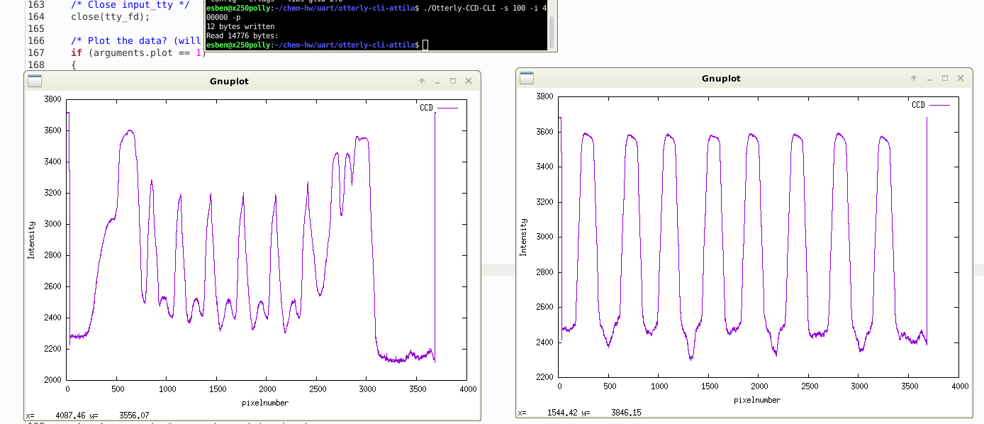
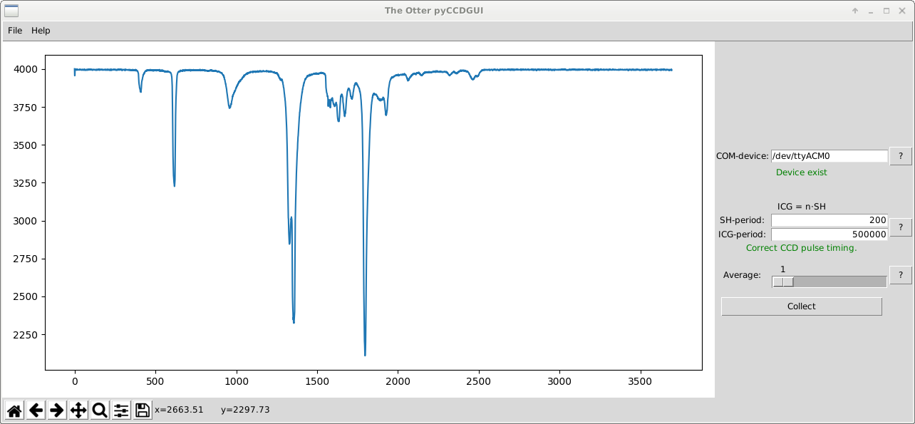
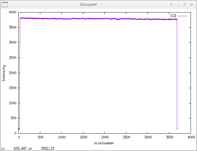
Reading the TCD1304:
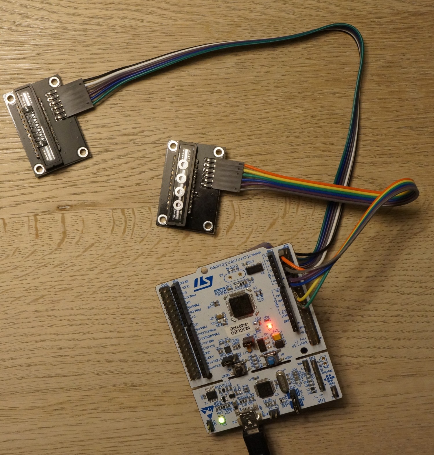
The data rate of the CCD is 1/4 of fM, which means the pixels are clocked out at 0.50 MHz. The ADC in the STM32F401RE is fast enough to do 12 bit conversions at this rate. The pixel values are sent to a 16 bit array using DMA. From here they are sent to the Raspberry Pi over SPI at 16 MHz - also utilizing DMA - or through UART to a regular PC via the built-in ST-link's USB-connection.
The voltage of an "dark" pixel is around 3.0 V and a "white" pixel has a voltage of around 1.5 V. In other words the data is upside down.
Total cost of the project:
Raspberry pi zero 5$ (optional)
Nucleo F401RE 11$
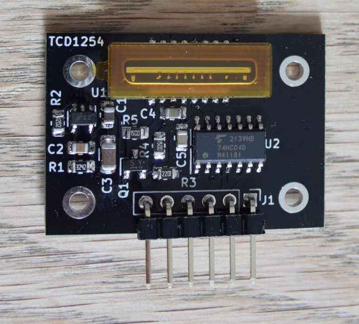
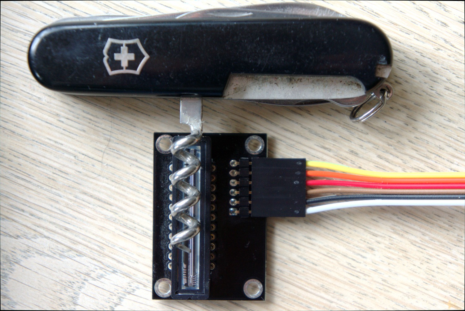
TCD1304 2-3$
miscellenaeous 5$
All in all it can be built for around 25$
More information:
The source code is littered with comments as best I could, so dig into it if you want to know more details about setting up the STM32F401RE's peripherals.
This project is part of The Otter DIY Raman Spectrometer. You can read more about that here: erossel.wordpress.com
License:
Everything comes with the FreeBSD-license, so do with it what you want. The only exception is the Nucleo F401RE which is under ST's evaluation license.


 Ashwin K Whitchurch
 Aleksa
 Colin O'Flynn
 Luke Valenty
this looks awesome! I’ve been hoping to make a scanning camera for years. It’s awesome to see that you’ve gotten this linear sensor working as a spectrometer!