To start this project I found a $5 used Samsung LCD display, RGB old style. Since I am using it for programming and learning I don't need high definition so RGB is fine. The first step was to see if the LCD worked. It seemed to power on fine and everything. At first I was planning on removing the High Voltage Power Supply Driver with a Low Voltage LED Driver from LCDPARTS.com. They sell LCD drivers, converter boards etc. to turn any basic LCD into fully functional display's.
After checking the display I took it apart and found it contained three boards. One a High Voltage Supply. Two a LCD driver and three the LCD backlight voltage driver. There was an empty space where cables had been routed and after measuring the raspi fit exactly in that little space.
I had to grind out the steel frame to let the raspi lay flat and afterwards the fit was really nice. At this point I had to decide how I was going to wire the cables. There wasn't enough room inside the case to route the rgb and HDMI converter. So I cut a few holes for the input power and hdmi connector. After checking the fit I went out to purchase a Cirago HDMI to RGB converter for about $30. This was the most expensive piece of the build. After hooking it up and testing it worked great. Proof of concept worked great.
Next I cut a few holes for the 4 usb slots to be accessible from outside the display, kind of like an all in one PC. This was the most difficult part and one that I think I would do different the next time around. I routed some cables to the usb slots I cut and after glueing them in place soldered the connection to the raspi usb slots. I had to check the wiring with a DMM after to ensure I wouldn't burn up the pi. After fixing a few wires that were swapped everything tested fine. I found it easier to leave the pi out of the case for soldering as It gave more room to work. Once everything was soldered I routed the cables around and plugged in the connections to the pi.
To ensure there were no shorts in the wiring I used a formable plastic to encase the usb wires. But I added too much and one of the boards didn't fit. After using heat and a scraping tool to remove glue I was able to get that bard to fit. Then I placed all the components back into the frame. This time the HVPS didn't fit well. So I had to cut the cover of the Raspi so that the HVPS would have enough room to be secured. This was done then the cover screws and tape were used to keep everything together.
Next I rough fitted the outer plastic cover onto the display and measured where the holes for connections needed to be. This was the easiest to cut and measure and went by the fastest. Still waiting on an sdcard extension so that I can swap out the sd card when or if it gets corrupted or I need to change OS images.
After everything is put together I tested it. The first time the display didn't sync properly and there where errors on screen. So I checked the cables, retaped and put everything back. Then I noticed the power supplies. First you have to turn on the LCD power then apply power to the Raspi or the LCD doesn't sync with the Raspi HDMI driver, also the power to the LCD converter needs quite a bit of power to work properly.
In the future I plan on adding a handle to the top or mounting this on a wall or something to stream music stations or use as an in car display.
 Auron
Auron
 Valrum
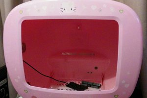
 Tim Savage