FloppidyDingo
-
New LCD Design
04/02/2016 at 00:36 • 0 commentsI have decided to save my current LCD for something else, and instead I'm using the NHD-2.4-240320CF LCD. Newhaven Display was kind enough to even provide sample code for using it, which saves me a ton of time. But since this LCD uses a different resolution, I'm going to have to redo the memory map. Yay, fun.
-
RIP Sandy the Soldering Iron
04/01/2016 at 18:42 • 0 commentsWell, Sandy the Soldering iron is officially retired. The tip breaking off also damaged some of the wiring, and the whole thing shorted out in a light show of sparks. Looks like I'll be getting a new one. It was about time the thing gave up, it lasted a good long while. Let us have a moment of silence for Sandy.
Some good news though: The boards for the game cartridges arrived today, a week sooner than expected. Once my new iron gets here, I'll order the rest of the parts and start testing the cartridges.
-
Reverse Engineering LCD Controller
04/01/2016 at 02:04 • 0 commentsA game console is nothing without some form of output, and LCD displays are expensive for the size I want. Lucky for me, a friend of mine gave me an old printer to tear apart, and now I have an LCD that very conveniently has an LCD controller board already made for me. Bad news is, there are no schematics for me to lookup, so I'm basically working with a black box. But this didn't stop me!
It was time to bring out my trusty multimeter and datasheets for the LCD (A025CN03) and it's controller (UGP051). Using those three things, I started probing around to find out what pin on the connector did and how I'm supposed to wire it. After some experimenting, I have came up with this possible pinout:
LED+ LED- LED- Control for negative voltage (?) +15V GND DCLK GND HSync VSync GND D7 D6 D5 D4 GND D3 D2 D1 D0 GND VCC VG resistor VG There are two pins I'm still figuring out. First is the control for the negative supply. I'm not sure if it's PWM, a digital enable signal, or an analog signal. If it's PWM, there is not feedback provided that allows me to adjust the frequency, so I think I can safely omit that possibility. Next is the VG pin. In one of the datasheets, there is a sample circuit that leaves this pin connected to ground through a capacitor. This is implemented on the board, so I think I can safely ignore that pin as well.
Once I get the signals figured out, then it's time to start coding. I have an ATMEGA328 to prototype with, then once I have a good signal, I'll port the code to work with the ATMEGA1284.
I tested my negative control signal, and no dice. I'm better off pulling out the IC and making my own controller board based off the sample circuit.
I done goofed. As I was trying to pull the IC off of the board, the tip to my soldering iron snapped in half. I tried to work with the short stub I was left with, and instead I wrecked the IC. Oops. It's a good thing I can get the exact same IC from Newegg. I'll just buy it from there and say I removed it successfully. Shhhh, nobody will ever know.
-
Fixed issue with naming scheme for Gerber files
03/23/2016 at 22:12 • 0 commentsThere should be four layers for the game cartridge, but when I uploaded the files to OSHPark, they only found three. This is because one of the files had a bad extension. This should be fixed now.
-
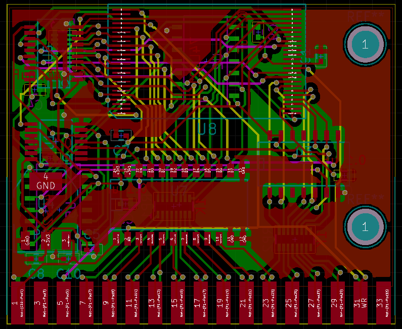
Finished First Revision of the Game Cartridge
03/15/2016 at 23:45 • 0 commentsAfter several redoes and hours of work, I have finally finished revision 1.0 of the game cartridge! It supports all chips from Macronix's MX29LV series (MX29LVXX), and only supports the regular bank swapping, so only 4MB maximum of memory is used. The next cartridge will have more bank registers to support larger storage.
I had to go to a 4 layer design so I can fit all of the glue logic used for voltage shifting and the swap register. The next cartridge will use a CPLD to handle most of the work, so the layout shouldn't be as complex. Here is a picture of the cartridge layout:
![]()
I uploaded a schematic of the cartridge as well. I have also uploaded the gerber files for anyone who wants to fabricate them.
So I examined the circuitry for the cartridges, and found that an address line is missing, so the cartridges are only capable of 2MB capacity. There is a little hack one can do to fix this, but I'll work on fixing that bug in revision 2.
The ZStation: an 8 bit game console
This little project is part of a series of consoles im making