• Video retrospective

    Raphaël Casimir05/23/2016 at 22:14 0 comments

    Check out our project video!

    It was due in French, but if you don't speak it just watch from 1:47 for the French cup or 1:00 for UK.

    We'll catch you next time ;)

  • Eurobot France

    Raphaël Casimir05/08/2016 at 12:30 0 comments

    On the 4-8th may 2016, we finally attended the French national robotics cup, organized by "Planète Sciences" a non-profit organization. We will speak here about the wheelbase redesign, the new electronics, and the new algorithms (more on that later).

    We attended a few days before the German robotics cup, but we were not able to play on the field due to a general motor controllers failure (yes, both of them), we think it was due to the way we cabled the emergency stop. Since there were too many design flaws to overcome to use the brushless motors like in UK, we decided to redesign the whole propulsion system based on stepper motors.

    That meant building new motor blocks, designing a new motherboard PCB and new algorithms in 3 days.

    Thanks to our modular design, the whole wheelbase hadn't to be redesigned.The former motor block was much larger and designed to support a gear reduction system.

    The former motor block assembled

    We made several iterations before getting to the right solution for the new blocks. We got through many problems with our 3D printer so we had to take it to the tournament for some one-site printing.

    However that forced us to to the lightest and smallest possible design and led us to a very compact motor block :

    The stepper motor we used was a standard NEMA-17-style one like this (5mm shaft) :

    The integration was quite easy, and we were just on time to be homologated

    The wheelbase fully integrated

    We drove the motors with a DRV8825 High Current Pololu stepper driver, powered by two LiPo batteries in series for 24V operating voltage, since it is less likely to skip steps with higher voltages in the engine coils (the magnetic field establishes itself more quickly). We used a THN 30-2412 Tracopower DC/DC converter on our board for logic and servo power supply.

    As you an see, we needed a quite large heat sink to dissipate the wasted energy from the 40W total propulsion system

    Here is a front-side view of the board :

    This PCB was designed as a shield for the Arduino Mega and has the several features

    • 5 standard PWM servo ports
    • 6 analog sensor ports for infrared and proximity
    • Quad input DIP switch
    • 3 Anti-bounce filtered push buttons
    • 1 filtered reset button
    • 1 Green LED
    • 1 Red LED
    • 1 starting switch port
    • A TRACOPOWER 5V 6A single output DC/DC converter (9-36V)
    • 2 Decoupled battery inputs
    • A 16x2 LCD Alphanumeric panel (great for debug)
    • 2 AMT10-V series encoder inputs (decoupled with standard 100nF capacitor like all active components)
    • 2 Pololu stepper driver ports (thus easy to replace) with heat sink supporting the high current version

    We used basic algorithms to drive the robot on the playing field, the whole strategy will be published in a few days with videos of the robot working at the Eurobot cup.

    We will try to publish our designs as soon as possible on GitHub.

    Thanks for reading ;)

      • Eurobot UK - Recap log

        Cyrille Benoit04/27/2016 at 23:58 0 comments

        Last week, our team went to London to participate to the Eurobot UK competition.

        The day before, our robot was not ready to compete at all : it was not able to move.

        Three members of our team made a sleepless night in order to prepare our robot which was ready on April, 21st's morning.


        We did a great job by understanding how to control the acceleration and breaking of the two brushless motors.

        Indeed, we firstly thought that when the brushless motor was receiving nothing while going forwards, it would stop. But it just stops the acceleration. To stop the robot, we had to use the opposite value to break.

        Same idea for going backwards, if you just ended up breaking, you had to return to the neutral position before using the "negative" value.

        Also, we decided to focus on the moving ability only and not the fishing arm because we ran out of time.


        In the morning, we went to the Middlesex University to do the last adjustments to our robot before the approbation. We used this precious last minutes to add the proximity sensor and allow us to move forward.

        After some adjustments on the robot height and the orientation of the flag, we got approved with our first prototype.


        The first match was stellar, our robot which was just able to go forward for 4 seconds before standing still until the end of the timer and open the flag beat a couple of robots which looked pretty powerful. We think we only won because their robots did not move from the starting area, but even then, the game and win were really really intense.

        The second game was a bit less stellar, but still. Our robot deviated a bit on the right, and did not push totally the items it had to. We won with a difference between the two team inferior to 5 points.

        The third and final game for us has shown a dysfunction with the moving system. Our robot trend to go on the right increased since the second match.


        This competition was for us a really good opportunity to test our robot and understand what would not work before the Germany and France Eurobot rounds.

        This week we've worked a lot on the issues our robot faced during Eurobot UK. We hope our work will pay and we'll go even further than our 12th position we got this time.

      • Funny action

        Aurélien04/26/2016 at 15:07 0 comments

        In this log we will present our solution for the funny action in the Eurobot competition. At first we thought about an umbrella shaped solution. Here it is the umbrella we did with SW, the blue ring is a 3D-printed part.

        The concept was to pull up the parasol out of a metal circle and gravity would deploy it.

        We were focused on an umbrella shape. This solution worked perfectly but the mechanism was too complex for such a simple task, increasing the risk of failure.

        So we worked to find another solution and here is our final version of our Beach umbrella.

        We were focused on an umbrella shape. This solution worked perfectly but the mechanism was too complex for such a simple task, increasing the risk of failure.

        So we worked to find another solution and here is our final version of our Beach umbrella.

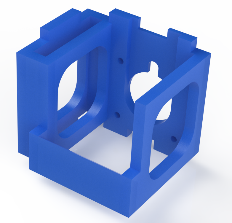
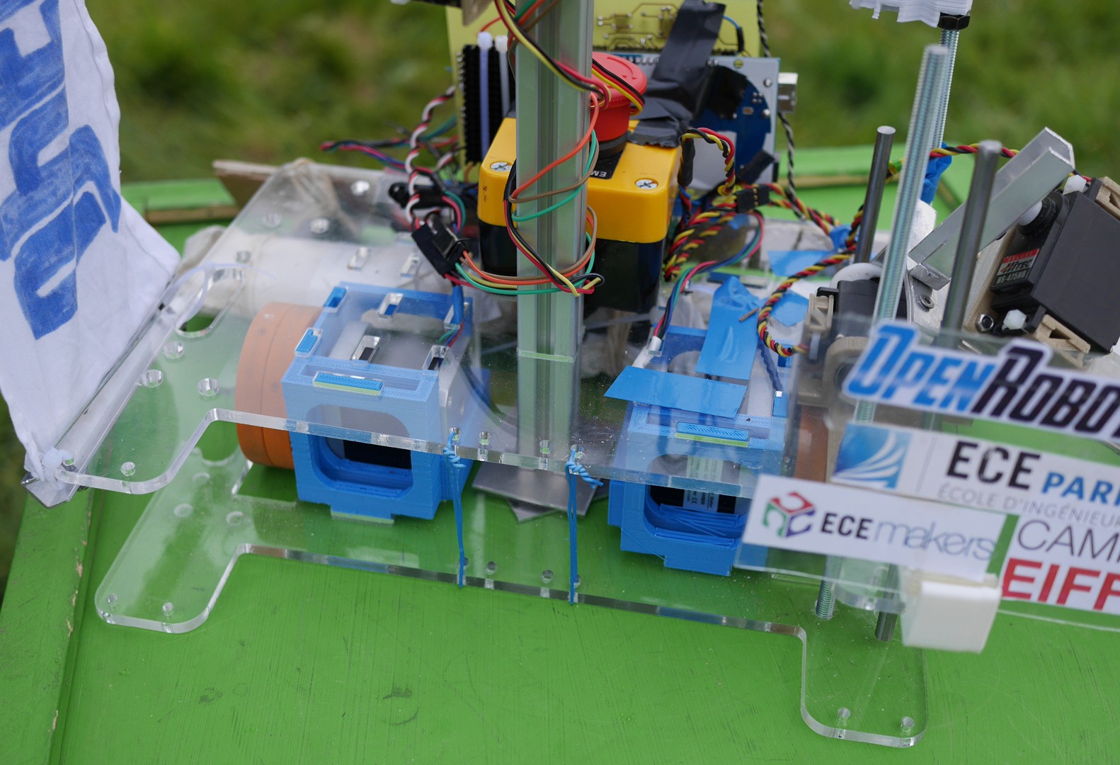
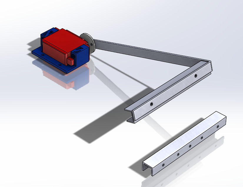
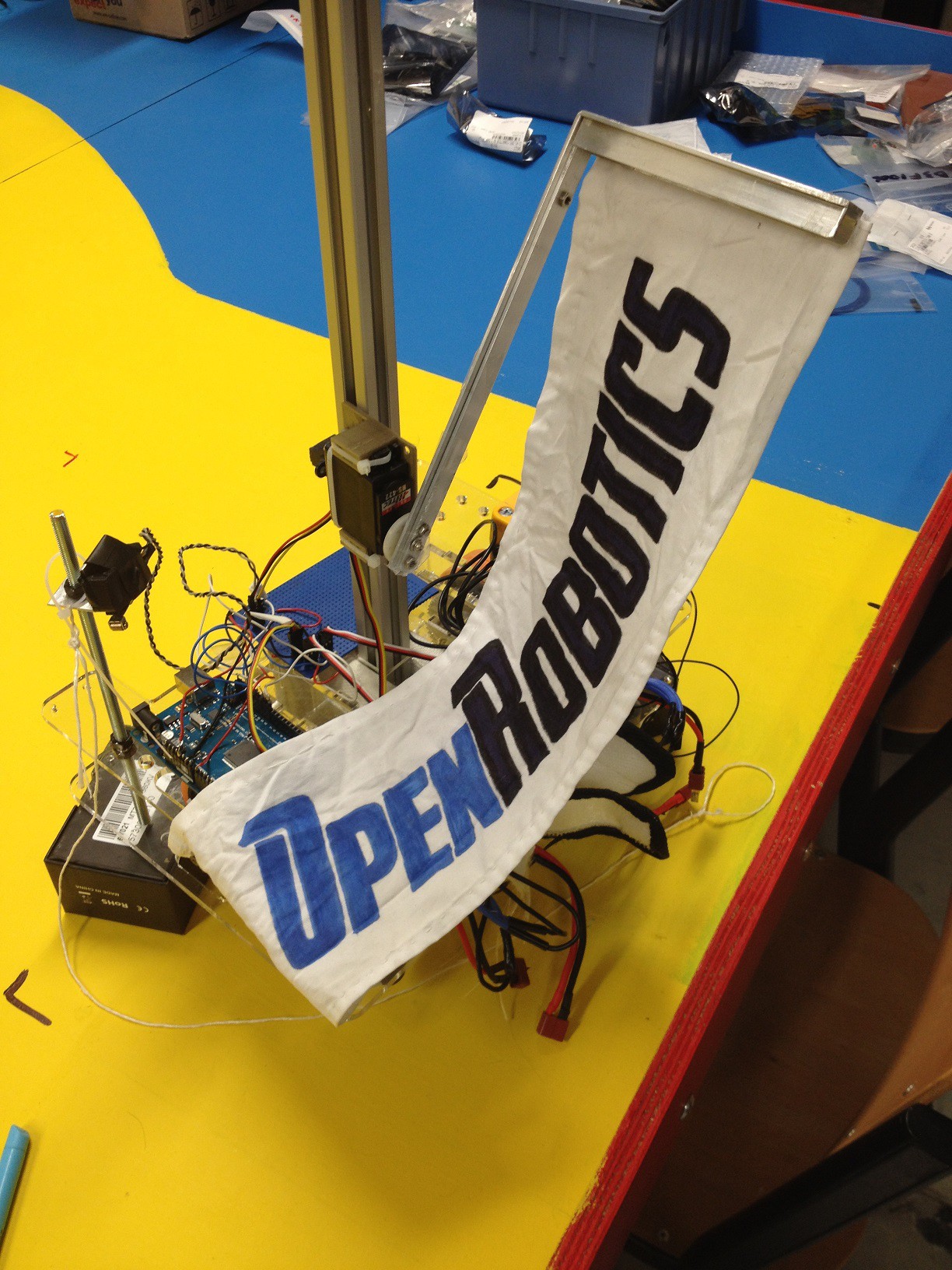
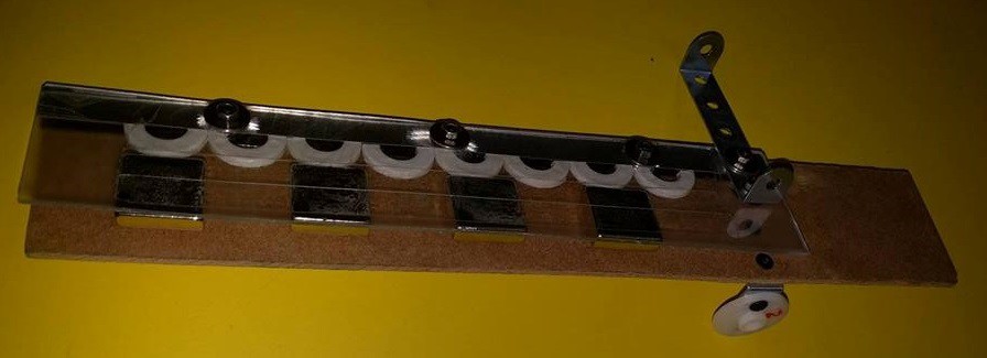
        The mechanism is very simple, the blue part is fixed on the robot and the bar in U is fixed apart. Then we hang together the two metal bar with a piece of fabric. On the right there is the support for the servo, which we designed to be reusable for other tasks.

        Here is our beach umbrella closed.

        And now open.

        We chose this solution because it is simpler to fit it on the robot and this option allows a bigger parasol with a more visible logo.


      • Fishing arm

        felix.navarre04/16/2016 at 10:04 0 comments

        As you know we are participating in the Eurobot competition (if you are interested check the rules here: http://www.eurobot.org/eurobot/eurobot-2016/rules). In this log we will present our solution to take floating plastic fishes out the water and put them in a net.

        So in order to catch those fishes we came with few solutions. The first one was a huge arm taking all the fishes in one round:But that solution had one major problem. We needed too much servomotors to make it works : one to rotate it , one to actionize it, another one move it up and down and another one to tuck it.

        When we realized that we decided to change our strategy and to use magnets to catch de fishes. We first designed an arm with mecano. That wasn’t smart because it was way to heavy.

        Then we decided to build our own arm with wood and plastics.

        The concept is quite simple we pass the arm above the fish and they get caught with the magnet on the arm.

        As you can see in the videos we are using one servo for the up and down movement and another one to free the fishes.

        Now we know it’s working we can start the real one.

        Stay tuned for more info

      • ​Setting up a project manager

        Raphaël Casimir04/13/2016 at 23:15 0 comments

        We are working on getting Restyaboard to work (with Docker), and we're nearly there.

        As you can see the e-mail confirmation is sent and correctly formatted, but... the link doesn't activate the account. Just opened a new GitHub issue for this.

        The other functionalities seems to be working properly. Stay tuned.

        When the manager will be working as expected, I will post our boards and hope the whole team will use this tool for you to be able to see our internal organisation.

      • Coanda-effect cooling system for 3D printing

        Raphaël Casimir04/09/2016 at 11:11 0 comments

        We needed a functional 3D printer to produce our actuators and other mechanical pieces. The meccano prototypes were not very precise and seemed very "amateur".

        We had a 3D printer that lacked a cooling fan for the extruder output. With no fan, the printing quality and possibilities are very limited since the extruder passes over and over on a plastic that had no opportunity to solidify. As a consequence, the printed object looks very mushy and the overhangs... just not possible.

        Here is an example of an object printed without any cooling fan :

        The ideal cooling system needs to be lightweight, produce a good airflow and focus it on the extruder output and not any higher since the hotend needs to be at a stable temperature to extrude a regulated flow of plastic.

        Old system :

        On the left is a sectional view of the fan duct. Another popular system is to condense the flow to obtain a higher output speed. But these two are not efficient solutions.

        Most popular fans uses the same effect than plane wings to produce airflow. This is a solution that is great at producing high flow but low air pressure. Other fans can achieve both, these are blower/turbo fans, which are much more expansive, heavy, loud, and inconvenient to mount. Moreover they have a fairly lower size/flow ratio.

        The fan duct solution above restrain the flow so higher pressure builds up in the chamber on the left which stops the flow and makes the air going intermittently backwards. Thus it is a very poor solution.

        Regular vs. blower fan :

        Our solution is to use the Coanda effect to be able to let the fan breathe freely and direct the flow efficiently. This effect describes how the flow has the tendency to stay attached to a convex surface.

        Our system had 3 iterations, the latest is presented below and all files will be included in our GitHub:

        A previous iteration used to print another one:

        The latest iteration, which has shown very good results, with a very high flow produced just at the extruder's extremity and none on the heat block itself:

        Stay tuned, we will upload the source and production files shortly.

        Thanks for reading this long post ;)

      • One left to be modeled

        Raphaël Casimir03/30/2016 at 09:55 0 comments

        All of the wheelbase components are modeled except the structure that holds everything together. We decided to laser-cut it in acrylic plastic, using the less quantity possible to keep the cost down.

        Acrylic is transparent, so the motor/gear/wheels system will be visible, for educational and checking purposes.

      • AMT10 Encoder setup

        barbier.charles103/29/2016 at 18:23 0 comments

        In our project we chose to use the encoders from the AMT10 series ($23 at Digi-Key, datasheet: www.cui.com/product/resource/amt10-v.pdf). Here is how to use it, the simple way.

        We will explain the mechanical setup later, first let’s concentrate on electronics and programming.

        These encoders works with a direct current between 3.6 and 5.5V, 5V being the nominal voltage. There are 3 different data output pins, the index “I” sends a pulse each time the encoder makes a full rotation, the pins “A” and “B” switch between high and low logic states each time the encoder makes a certain fraction of a full rotation. This fraction / the resolution of the encoder can be set thanks to a DIP switch on the encoder from 48 to 2048 ppr (pulse per revolution).

        A and B have the same frequency but B is a half period late compared to A. This way when turning clockwise B is at low state at when A is rising edge, but when turning counter clockwise B is already high at each of A’s rising edges. This allows you to know which way you are going by reading B when A is rising edge.


        I have written a short code you can use to test your encoder and see how it works, I have noticed that when using an Arduino uno some pulses are skipped when the resolution is over 100 ppr, seemingly because the microcontroller isn’t fast enough. Also, we do not have fixed the encoder axis, so lateral movement may tamper with the capacitive sensor in the encoder.


        int A = 12;
        int B = 11;
        int I = 10;
        
        int countTick = 0;
        int countIndex = 0;
        char precTick = 0;
        char precIndex = 0;
        char tick = 0;
        char tickB =0;
        char index = 0;
        
        void setup() {
          pinMode(A, INPUT);
          pinMode(B, INPUT);
          pinMode(I, INPUT);
          Serial.begin(9600);
        
        }
        
        void loop() {
          tick = digitalRead(A);
          tickB = digitalRead(B);
          index = digitalRead(I);
          
          if(tick != precTick)
          {
            if(tick != tickB)
            {
              countTick = countTick + tick;
              precTick = tick;
            }
            else
            {
              countTick = countTick - tick;
              precTick = tick;
            }
            Serial.print("tick :");
            Serial.println(countTick);
          }
          
          if(index != precIndex)
          {
            if(countTick > 0)
            {
              countIndex = countIndex + index;
              precIndex = index;
            }
            else
            {
              countIndex = countIndex - index;
              precIndex = index;
            }
            countTick = 0;
            Serial.print("turn :");
            Serial.println(countIndex);
          }
          
          
        }

      • Precision

        Raphaël Casimir03/21/2016 at 08:17 0 comments

        I just finished the assembly trimming for the motors. This is precision ;)