Close
0%
0%

Retro Flip Display

A USB electromechanical display using Ferranti Packard 7-segment digits.

Similar projects worth following
I'm building a five digit, electromechanical 7-segment display controlled via USB or serial.

The primary goal is to have a clacky live count of open tickets at work, but the design is general purpose and could be used for anything - unread email count, your personal best number of open tabs, the number of tasks you've accomplished today, a random five letter word, or the number of hours until some event in the next 11 years.

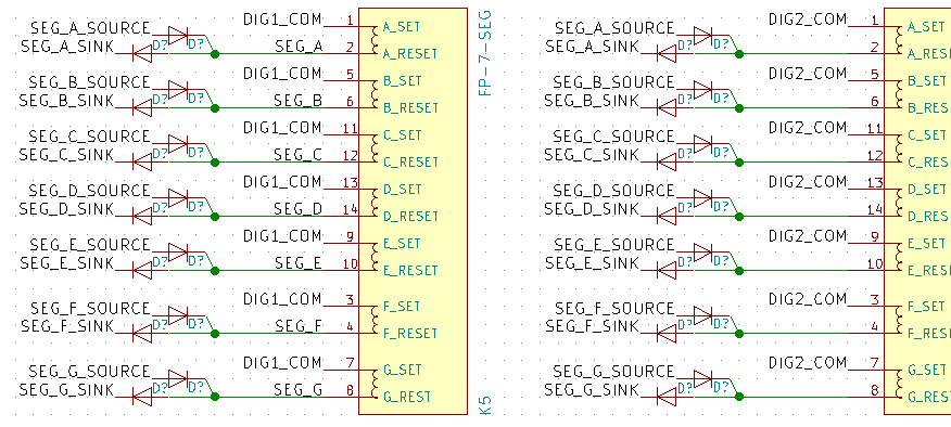
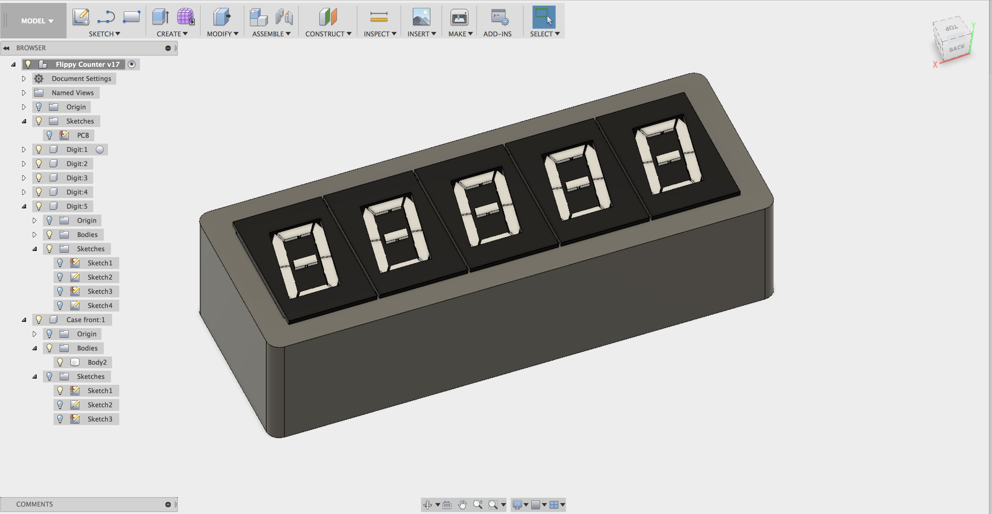
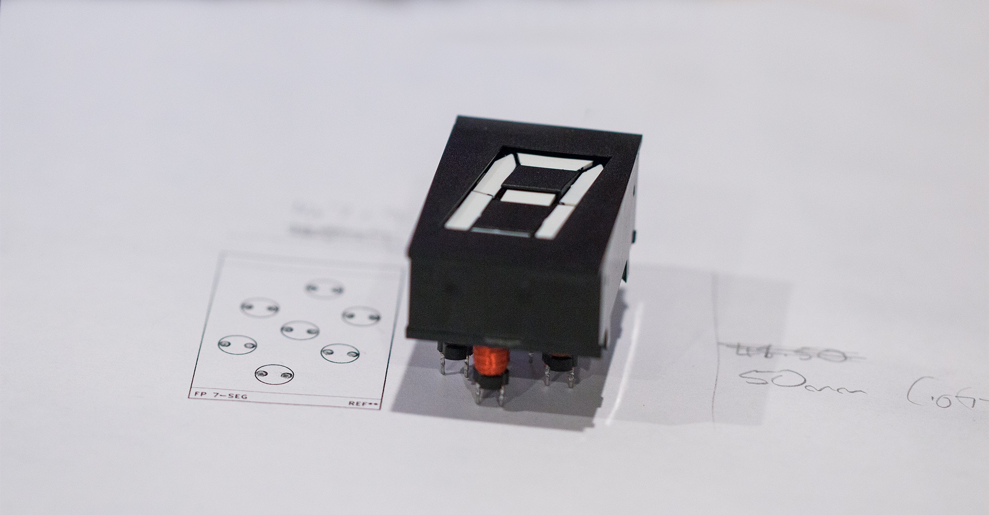
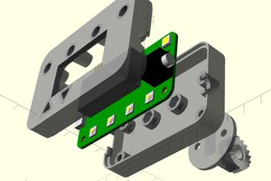
The display is comprised of 5x 1" Ferranti Packard FP-00SS5-7 units. I picked these up as new-old-stock on eBay, but they're also currently manufactured to the original spec as Alfa-Zeta S7S.

  • Ferranti Packard display driving requirements

    Stephen Holdaway03/25/2018 at 08:17 0 comments

    The datasheet/brochure for the FP-00SS5-7 displays doesn't give much information about what's required to drive them. It gives an example of 16V at <350mA for 1ms, but I wanted to check how the segment flipping performed under different conditions.

    To pulse power on demand for arbitrary amounts of time, I grabbed an IRFZ44N MOSFET and hacked together a not-entirely-accurate, but good enough serial console on an AVR microcontroller (code here):

    Results

    As expected, the segments flip fine using the datasheet value of 1ms @ 16V.

    Segments start to move at about 9V, but the field generated is barely strong enough to keep a segment held in place. From observation, 12V seems to be the minimum voltage to drive segments firmly/reliably.

    At 16V, segments will flip when powered for >100µs. The field is a bit weak at with this small amount of total power though, and rattle around if the display is moved:

    At 16V, segments work perfectly fine when energised for >=500µs:

    Thoughts

    Segments don't look like they'll hold position reliably with <500µs charges, but using shorter pulses does have one advantage: the display makes less noise as the segments have less kinetic energy when they hit their stops.

    A reduced noise update strategy might be possible by nudging segments into place with a small pulse, then energising again afterwards with more power to hold the positions firmly.

  • Multiplexing H-Bridges (aka. discrete components everywhere)

    Stephen Holdaway03/25/2018 at 03:11 0 comments

    After feeling that the first driver design using half bridges wasn't an ideal solution, I've had a go a reworking the segment drivers to use a multiplexed H-bridge configuration:

    This is similar to the design that Coyt Barringer used in his clock using these displays, though I've saved one GPIO per digit by having the digits alway connected to 16V or GND at the expense of a slightly more complex driving sequence.

    Turns out, this design has its own downsides though... mainly the sheer number of discrete components involved.

    The half-bridge driver design needed 86 components for the driver and digit select:

    • 70 components for segment drivers (10 for each of the 7 segments)
    • 10 components for digit select (2 per digit)
    • 6 components for the split rail supply

    A multiplexed H-bridge on the other hand requires 156 discrete components:

    • 56 components for segment source/sinks (8 for each of the 7 segments)
    • 30 components for each digit source/sink (6 per digit)
    • 70 diodes to prevent unwanted current flow: 2 per segment, per digit.

    Cost is a factor

    Doubling the component count is a bit eye-watering when thinking about layout and manual assembly, but let's see what the costs are like, ignoring shared components, resistors and capacitors (since they cost about the same in each design).

    Split rail push/pull

    PartQuantityPer unitSubtotal (NZD)
    30V 500mA NPN BJT (MMBT2222ALT1G)14$0.05$0.70
    -60V 500mA PNP BJT (MMBT2907ALT3G)7$0.05$0.35
    30V 1/2W Zener diode (D3Z30BF-7)14$0.206$2.88
    Solid-State Relay (AQY282S PhotoMOS)5$2.30$11.50
    40V 1A Op Amp (TCA0372BDP1G)1$1.17$1.17
    Total$16.60

    Multiplexed H-Bridge

    PartQuantityPer unitSubtotal (NZD)
    >20V 500mA NPN MOSFET (NTR4003NT1G)12$0.265$3.18
    -20V >500mA PNP MOSFET (DMG2301L-7)12$0.316$3.79
    18V 1/2W Zener diode (DDZ18BSF-7)14$0.206$2.88
    1/2W Diode (BAS16J)70$0.085$5.95
    NPN BJT (MMBT3904)12$0.047$0.56
    Total$16.36

    ...Well, that doesn't help the decision process much! Even though the H-Bridge design has more components, I'm going to continue with it for now. I'd rather have a greater number of generic components than locking the design into vendor specific parts.

  • Second thoughts on the first design

    Stephen Holdaway03/22/2018 at 11:51 0 comments

    I've been tinkering with this project for about a week so far. Initially I spent a while messing around in Falstad's interactive circuit simulator (above) to figure out how to multiplex and drive these displays.

    Segments are switched on and off by powering the appropriate coil briefly in forward and reverse polarity. The datasheet suggests driving the coils at 16V current limited to 350mA. In bench tests the segments flip from about 9V up, though the field generated is a little weak under 12V.

    In the interest of lowering component count, I was curious if I could pull off a driver using half bridges, similar to a push-pull amplifier. Bi-directional driving is often done with H-bridges, but my curiosity got the better of me.

    The first pass on the schematic boosts the 5V USB supply to 24V and splits it to a common 12V for the segments. There's a pair of transistors in a push/pull configuration for each segment, attached to all digits. The digits are selected by enabling a PhotoMOS solid-state relay that connects them to the 12V rail.

    There's a few disadvantages with this split-rail design however:

    • Need to generate twice the coil drive voltage:  the voltage across the display coils will only ever be half of the total generated in either direction. Maximum ratings of components start to become a problem around 30V. 
    • Larger and more expensive components: the op amp splitting the rail needs to sink and source around 500mA, which I haven't found in a package smaller than a DIP-4. The PhotoMOS solid state relays work, but are much more expensive than a few SOT-23 transistors per digit.

    This split rail supply works fine in theory, but the real-world components to make it work with 300-500mA pulsed currents are excessively expensive. Using a dual supply to get +15V and -15V at the required currents has similar issues with cost, though it removes the need for a big op amp.

    Other updates

    I've roughed out an enclosure design to get an idea of PCB size:

    PCB layout is on hold until I've revised the schematic, but I started on this. Needs some thought about mounting.

    Tested the footprint for the displays - it fits well:

View all 3 project logs

Enjoy this project?

Share

Discussions

Briand wrote 01/30/2019 at 23:28 point

I am hoping to create a similar project (iot connected counter) with these displays. I would support and purchase a built pcb ! I am a complete novice and would appreciate any guidance at all regarding linking the displays in series and controlling via polling an api.

  Are you sure? yes | no

Daniel 'Fun' Segel wrote 05/03/2018 at 02:46 point

Cool, I've been working on something similar off and on for a while now. My approach was much more minimal, though - check out my proof of concept here: https://youtu.be/pfwrARCU7BI

I'm using an Arduino Nano (and Pro Micro in the video) to drive an L293D to provide +/-20V, and VO3021 opto-triacs to drive the segments. One problem I have is that when I have multiple displays hooked up with a common side for the segments (as you are doing), they all trigger when I drive just one of them. I think the collapse of the field when the coil is de-energized is enough to trigger the other segments to flip. I have ideas for a workaround but haven't gotten around to implementing them yet.

  Are you sure? yes | no

Stephen Holdaway wrote 05/03/2018 at 03:23 point

Nice work, looks like a nice compact solution. Do you have a schematic for that setup? Also, how long are you driving each segment for? At 20V a few hundred microseconds ought to be plenty from what I saw experimenting.

The L293D seems relatively expensive looking around - how many do you need per digit?

  Are you sure? yes | no

Daniel 'Fun' Segel wrote 05/04/2018 at 20:40 point

I'm multiplexing so I only use oneL293D in all; the voltage is switched to whatever digit and segment I need to flip. Once flipped they don't need voltage any more. At worst I'd use one per digit. Like you I used one side of each coil as a common connection, and if that side is set to the same potential as the voltage being sent to the segments then nothing happens. My latest plan is to use a relay (one per digit) to switch the common line to either + or - voltage depending on what I'm using to flip the segments.

I have schematics of various versions, but they're not complete. I'll see if I can cobble together something showing the basics of how I did it.

  Are you sure? yes | no

Bastiaan wrote 03/23/2018 at 13:55 point

@Stephen Holdaway thanks for the link. They are pretty costly, so I understand your reasoning. I'd love to build a clock with 6 of these digits, for clicking sounds every second. Unfortunately a bit expensive for now, so I'll hold on to the link. Thanks and good luck with your project!

  Are you sure? yes | no

ActualDragon wrote 03/22/2018 at 13:57 point

these are awesome, any plans to sell some?

  Are you sure? yes | no

Stephen Holdaway wrote 03/22/2018 at 18:56 point

I wasn't planning to, but it would be easy enough to sell an assembled driver board  with firmware in small quantities if there's interest. The display digits themselves are the most expensive part at $9 USD each in single quantity for new-old-stock, but Alfa-Zeta still manufactures them which might be cheaper in bulk. I'll definitely consider it 👍

  Are you sure? yes | no

Bastiaan wrote 03/23/2018 at 06:59 point

Can you still buy them on eBay and the like? I couldn’t find them but maybe I’m looking for them wrong. Awesome project, is there a reason you chose 5 over 4 or 6 digits?

  Are you sure? yes | no

Stephen Holdaway wrote 03/23/2018 at 07:06 point

@Bastiaan Yeah they're still available, this is the listing I bought from:

https://www.ebay.com/itm/7-segment-1-Ferranti-Packard-electromechanical-display/160945344354?epid=1848339022&hash=item2579170f62:g:36cAAOSwzrxUtXEM

I chose 5 digits partly for cost reasons, and partly because 4 digits seemed too limiting for a general purpose display and 6 seemed too many for the intended purpose - our JIRA backlog isn't quite that bad ;)

  Are you sure? yes | no

Stephen Holdaway wrote 05/03/2018 at 03:37 point

Update on this - I contacted Alfa Zeta a few weeks ago, and an order of 500 new digits shipped would cost a few dollars more per unit than the new old stock from ebay currently does shipped (while it lasts). It might be a little cheaper if I didn't need to ship them all the way to New Zealand to manufacture.

The current design of the PCB uses a lot of discrete components, so it would probably take too long to assemble these by hand. With PCB + PCBA cost + BOM + overhead, I suspect an assembled board without digits might need to be priced at $50 USD or higher on a site like Tindie, excluding shipping. Not sure if there'd be interest in that, but I'd be happy to sell bare PCBs to get rid of spares at least.

  Are you sure? yes | no

Similar Projects

Does this project spark your interest?

Become a member to follow this project and never miss any updates