 zakqwy
Ha! This project isn't dead! Just resting.
I finally got started on thermal performance testing. To review: Using the larger (9") props seems to give me adequate thrust, but the motors heat up a bit too quickly. I went on a severe tangent designing and 3D printing motor cooling ducts and various venturis, and modified the motor mount to accept these new parts.
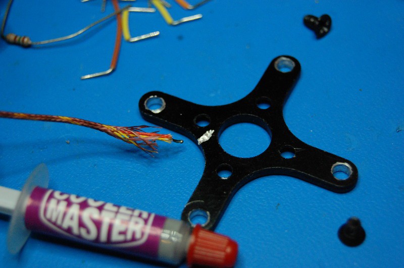
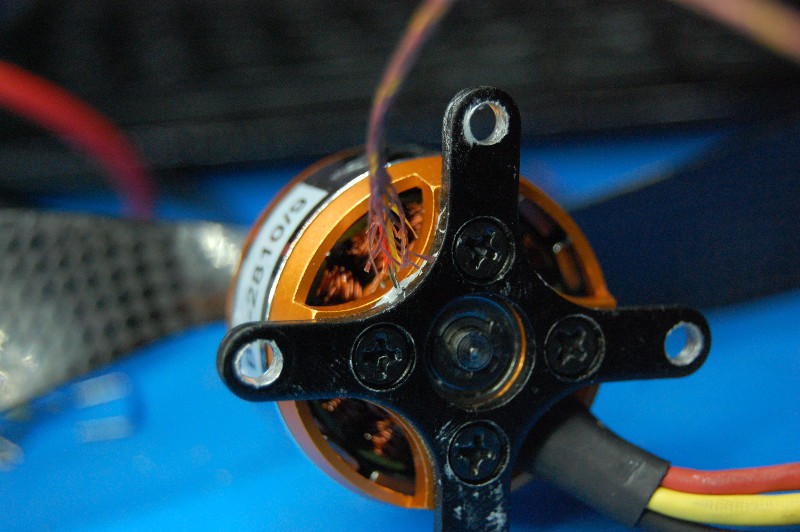
In order to prove (or disprove) the efficacy of the parts, I also embedded a thermocouple in the motor frame to track its temperature in real time during tests. Okay, to be fair--embedded is a bit of an exaggeration. I filed a groove in the motor bracket, globbed on some thermal transfer compound, and smashed it against the back of the motor frame:
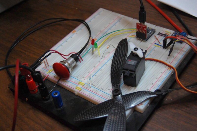
I also put together a pretty simple data acquisition and control setup using a Pro Mini, Adafruit's MAX TC board, and a handy serial datalogging program called GtkTerm. I included a few run status LEDs, a button (yup, it's my favorite giant red button) to start the prop rotating, and a servo to indicate the current ESC signal:
The first test was hilarious. It's been awhile since I've worked on GimbalBot so my work area wasn't quite to prop-safe levels of cleanliness. I ramped the motor up for the first time and heard a loud BANG--never a good sign. The prop had sucked up a stray Home Depot receipt and exploded it:

I broke for a bit of cleaning and then started running instrumented tests. Since the last time I've posted, I've finally entered the 21st century--I've got a GitHub repo now! The Dropbox directory still holds pictures, models, and old code; however, I'm going to start using the repo for firmware if not other stuff moving forward. Navigate to GimbalBot/data for the first performance tests, or just look at this graph:
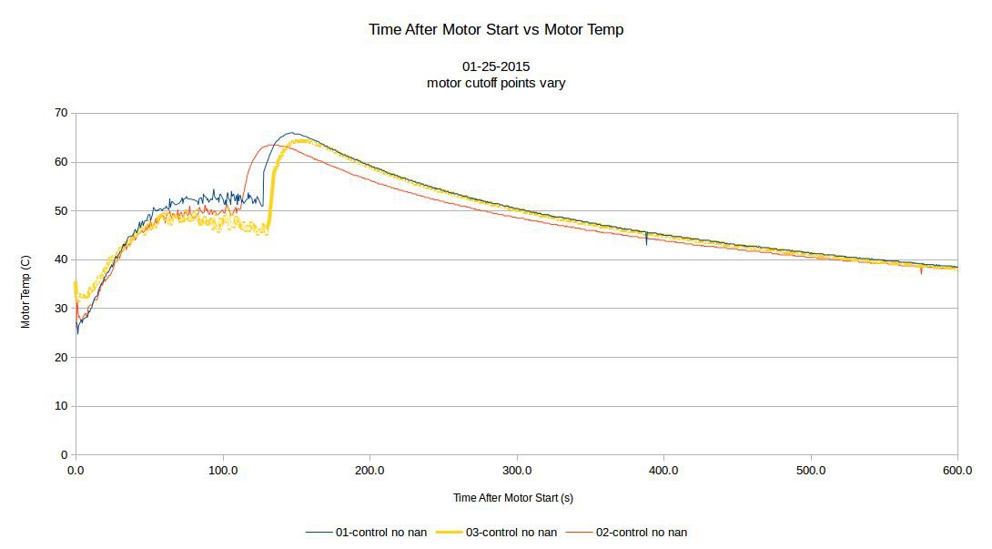
Details:
- 3 runs under identical conditions
- Motor PWM output: 100 degrees
- 8" props (nothing crazy yet)
- Thrust: 1210-1215 g
- No fancy cooling setup--cooling ducts removed, holes taped over
- x=0: motor turn-on from ~25ish C
- Various motor cutoff points, shown by the temp spike (I estimated these)
- Some data points eliminated due to noise (the TC board returned 'nan', or 'not a number')--hence, somewhat jagged spikes. Linear extrapolation for missing data.
- Data acquisition rate: 2 Hz
The program is set up as a "dead-man's switch"; that means I had to keep the button down to keep the motor running. I did this mostly for safety reasons; in the future, I'd like to standardize the test time so the cutoffs happen at the same point. A few takeaways:
- The motor temperature stabilizes eventually, but the approximate stability point varies by ~10 degrees or so across 3 runs. I'm not sure if this is due to thermocouple drift or air temperature variations or something else; maybe I should run more tests with identical conditions.
- The slope of the heat-up seems pretty consistent. I should probably quantify this with an error and use that to compare performance.
- Motor temperature takes a big spike up as soon as the prop stops rotating! Looks like the motor's built in cooling ducts are already doing something here; the temp rise after motor shutdown is 15+ C, and it happens fast.
Okay, hypothesis time!
- Cooling ducts vs taped over holes will be an improvement with venturis or no venturis. More airflow, right? Hopefully?
- Best performance will happen without any venturi insert (just an open hole). Why? I think my venturi design will restrict airflow too much and the venturi won't generate enough DP to flow very much air through the relatively small holes in the elements' necks.
Stay tuned..
Discussions
Become a Hackaday.io Member
Create an account to leave a comment. Already have an account? Log In.