 zakqwy
Napkin calculations: often done at a bar, on a napkin, with a marker (or a toothpick dipped in Angostura bitters). In this case, it's time to do some very rough calculations to figure out if GimbalBot is destined to fly. To do that, I've started finding various components and tracking their weight; see the GimbalBot BOM for this info (I'm keeping it separate from the finances spreadsheet, since the BOM will ideally only track stuff that goes into each version rather than overall project expenses).
First, how much thrust do we need? Diving in to the multirotor community, there are a few calculators out there that estimate static thrust based on propeller design (pitch, diameter, and type), air density, and RPM. They also spit out motor power requirements, presumably assuming 100% motor efficiency. I putzed around with this one a bit (screenshot of my ballpark configuration shown with a link below that):
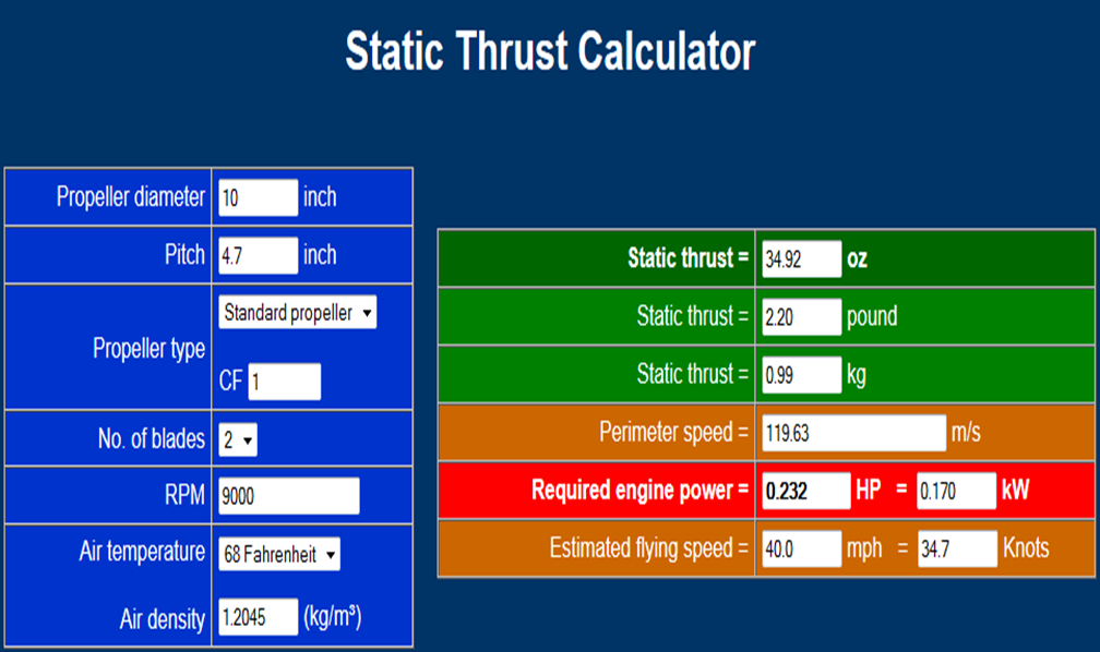
http://personal.osi.hu/fuzesisz/strc_eng/
Why 10x4.7 on the prop? Seems like a common size available in the quadrotor world. Why 9000 RPM? Well... based on my calculations, the motors I've found seem like they'll hit that given the required power calculated above:
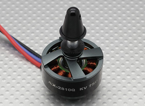
After playing around with HV stuff a decent amount as a kid, I got confused initially by the 750kv designation (that's scary!). Turns out for brushless motors, that's a key spec: RPM per voltage. In my case, driving this motor at 12vdc should give me 9000 RPM, assuming I stay under its maximum power rating of 333 watts (well, that's at 11.1 volts, so let's call it 350W). Based on the prop loading to produce the thrust calculated above, it seems like I should should have power to spare. Thrust increases dramatically at increased RPM; going up to 10,000 with the prop shown above increase the thrust from 990g to 1230g at 234W motor power; provided I can give the motor 13.3 volts, this should be attainable. (side note: assuming the tool calculates thrust with respect to Earth's gravity, I should probably be thinking about this in terms of Newtons: in that case, the above example gives us 9.7 N and 12.1 N thrust, respectively).
So... to use this information for GimbalBot design, we have to make a few big assumptions:
- Running two of these prop/motors coaxially in a contra-rotating configuration will sum their respective thrust outputs.
- The interference caused by the thrust plate, pitch ring, theta servos, and slip ring getting in the way of the propellers won't be too detrimental to effective thrust output.
To be somewhat conservative (hopefully conservative enough), we'll assume that the stuff blocking the propeller will reduce it's total thrust by 20%. Ideally, we'd do some fancy CFD modeling to see if this is the case at different flow velocities; given my lack of experience with these tools, I'm guessing I'd screw up a mesh design and get bad data out. Either way, 10k RPM - 20% can round up to 19.6 N, or an even 2 kg of static thrust.
Step one: make GimbalBot lighter than 2kg. Step two: Try to improve the power:weight ratio further. It seems like a lot of folks in the quadrotor community strive for a 2:1 thrust:weight ratio, but I think as long as I stay above 1.5:1 I should be in decent shape, at least for slower flight. Remember, I'm not trying to build an aerobatic drone carrying an FPV camera; I just want something that hovers nicely.
On to the next issue: I need to get 14vdc at 20+ amps (based on the 234 watt calculation + some fudging) to each motor to hit 10k RPM on a 10x4.7 prop. Call it 50 amps total with the theta servos. Trouble is, commercial slip joints seem to be sized for higher voltage and lower current loads. My excellent cousin Curtis suggested sending higher voltage through the slip ring and dropping it for the motors. I've found a few tiny DC-DC converters on Digikey that might do the job, but I might also keep an eye out for lower-kv brushless motors that are intended to run at 48+ vdc. That means the speed controllers need to be properly rated, and the theta servos (and RF receiver) will still need 6vdc. Hmm.. More to come. Suggestions, as always, are welcome.
Discussions
Become a Hackaday.io Member
Create an account to leave a comment. Already have an account? Log In.
Are you sure? yes | no
Are you sure? yes | no
http://apps.geindustrial.com/publibrary/checkout/QBVS050A0B?TNR=Data%20Sheets|QBVS050A0B|generic
Are you sure? yes | no
Are you sure? yes | no
In general, my understanding is that contra-rotating designs have two advantages once you get beyond their inherent complexity: they can pull a bit of lost rotational energy out of the 'top' propeller slipstream to increase the overall system efficiency, and they eliminate the torsional effect of a single propeller that forces most helicopters to use a tail rotor. Since I'd like my design to retain as much radial symmetry as possible (and I want my control system to focus on balance, not counteracting rotation around the craft's thrust vector), such a design seems like a good fit for GimbalBot. Make sense?
Are you sure? yes | no
Are you sure? yes | no