 zakqwy
Okay, so the title is a bit of an understatement. If you've been keeping up with the logs and project comments, you'll know that a few of the ideas that have been discussed conflict with the previous waterjet-cut CFRP design. I decided to explore other construction techniques; CAD models are in the Dropbox repo under /v07:
Many things to consider here. We'll cover them one at a time.
Thruster Motor Mounts
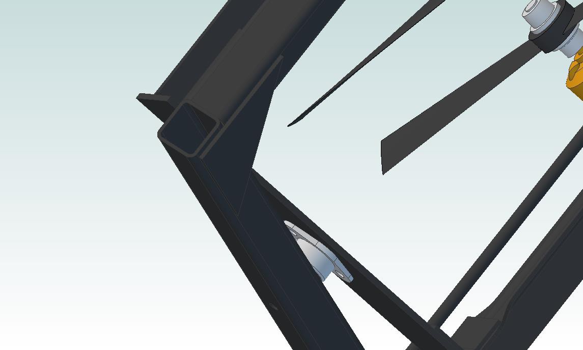
I added the black painted aluminum motor adapters that came with the motors. They're much easier to attach to the CFRP angle stock, and they also have a hole to clear the part of the shaft that sticks out of the back of the motor body:
(ignore the offset angle bracket cutout, I need to fix that...)
Thruster Motor Brackets
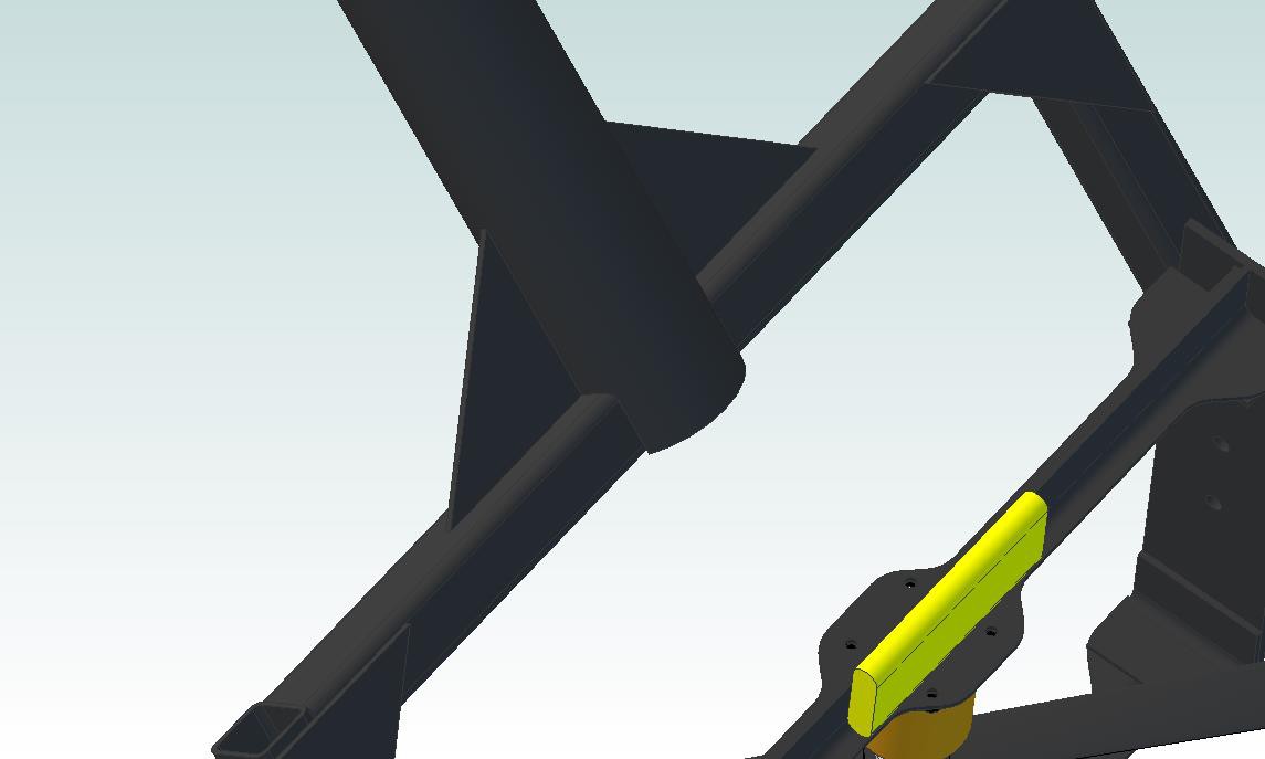
I completely ditched the thruster plate; instead, the motors are supported using a pair of sandwiched brackets that are trimmed back a bit to reduce their cross-section:
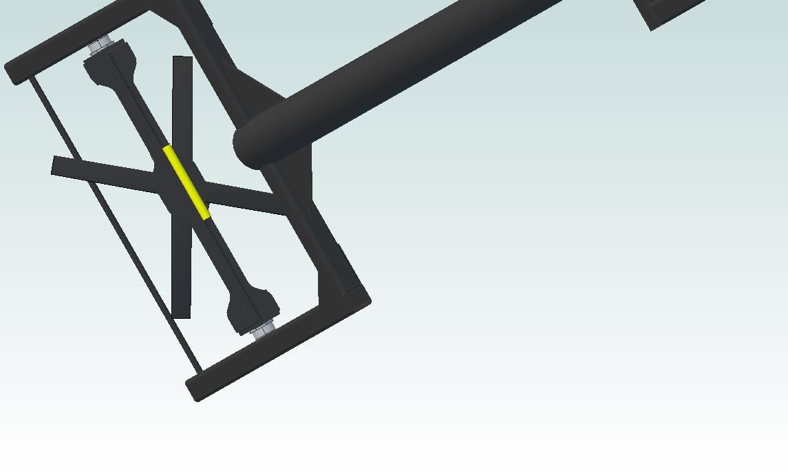
The picture above gives a decent head-on image of the fans, showing the portion 'shadowed' by the motor support. The two motor bracket pairs are then held together by 2.4mm thick CFRP plates:
It's rigid and doesn't require fancy waterjet work; I can cut the non-critical angle bracket profiles by hand. Space glue is pretty wicked stuff so I'm not worried about the joints pulling apart.
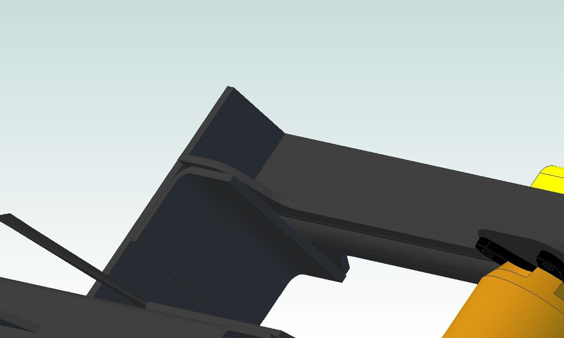
Tube Frame
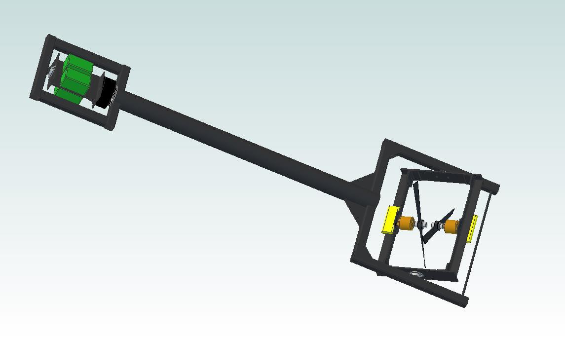
The thruster frame (I need to come up with more consistent names) is supported along the theta rotational axis using CFRP square tubing stock:
Hooray, gussets! These square tubes then connect to a central tube that forms GimbalBot's longitudinal frame:
Reaction Wheel
Sharp eyes may have noticed the lack of power converter and slip ring on the now-missing thrust plate. Unlike the theta servo (which just hasn't been drawn up yet), these items were intentionally left off the thruster plate. They're moving up!
If you're not familiar with reaction wheels, it's worth taking a look through the Wikipedia article. They're essentially masses that can be rotated relative to the main body of a craft to affect its orientation using conservation of angular momentum. By spinning the batteries one direction, I can cause the rest of the craft to rotate in the opposite direction in an extremely controlled fashion.
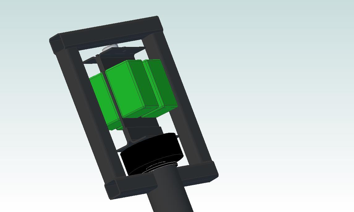
A few details on the picture above:
- The green boxes are the four 4S (14ish volt) LiPo batteries. I'll be wiring 'em in series, as discussed in a previous project log.
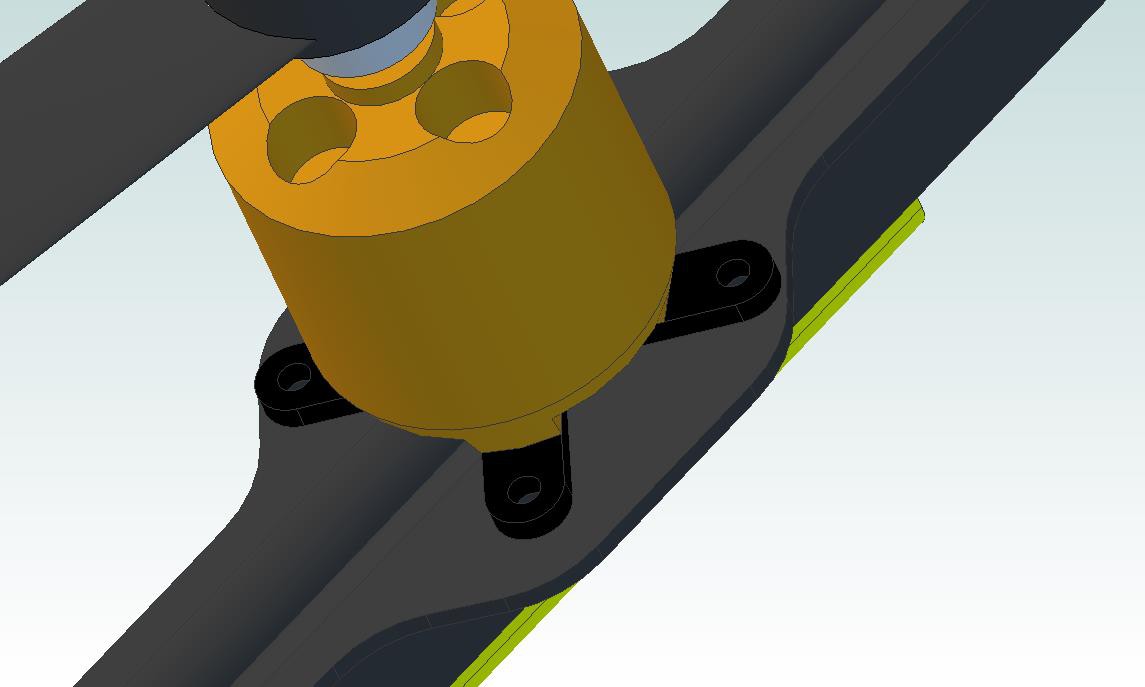
- The black hockey puck looking dealie is a brushless gimbal motor. These units are typically used to stabilize UAV cameras; this particular unit is designed for a 600-1200g camera, which is perfect for my batteries (they actually total 400 grams, so I might be going a bit overboard on the motor). Best part: it's got a hollow shaft, so it's a great match for a slip ring!
- You can't really see the slip ring; it's the black disk below the black motor, and most of its body is in the CFRP body tube. I'm still working out mounting details, so dimensions and such might change a bit. If you pull apart the model, you'll notice that the slip ring goes through the square tubing cross bar; yup, it's not quite finished yet.
Other stuff
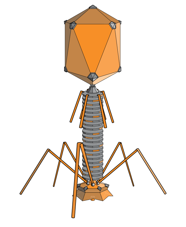
The Cortex M4 board, IMU board, and power converter aren't in the design yet. I'm probably going to put a control board plate below the slip ring and rho motor that will hold these parts. Additionally, I haven't added landing gear; I'm thinking about building something out of pulltruded 5mm CFRP tubing, since it's strong and light. This design is pushing me to consider changing the project's name to GimbalPhage:
In any case, I'm currently a tad over 1330g with the design shown above. Add in the converter, IMU, control board, theta servo/linkage, wire, and landing gear, and I'm probably pushing 1600g. Definitely need to get the thrust over 2kg if I want satisfactory performance.
Parts currently en route
- Slip ring (just arrived!)
- Batteries
- 4-gang battery charger
- Brushless gimbal motor
- Silicone-insulated 14-gauge wire
- Various battery plugs and adapters
- A bunch of different propellers (8 and 9 inch)
- Other random bits and pieces
Next steps
- Break out the Physics 121 textbook, re-learn how to draw free body diagrams, and try to figure out a few numbers (torque and actuation speed requirements, etc). I'll definitely need a hand on this one, my Newtonian mechanics is a bit rusty to say the least.
- Keep bugging the GE guy to sell me a damn power converter.
- Improve the thrust test results.
- Check full-RPM current values on the existing power supply; I think I'm probably maxing it out, so I might have some headroom left with the existing motor/prop combo.
- Test the new props as they arrive. The 9" units will require minor modifications to the thrust rig, but nothing too serious.
Thoughts? Questions? Comments?
-zach
Discussions
Become a Hackaday.io Member
Create an account to leave a comment. Already have an account? Log In.
Are you sure? yes | no