 zakqwy
Ah, tangents. Sometimes educational, sometimes helpful, sometimes a colossal waste of time. Always enjoyable.
I decided to spend a bit more time getting higher quality images of the PCB; I ended up un-distorting the pictures, scaling them identically, printing them out, and taping them back-to-back in an attempt to get a better feel for via locations. It kinda worked:
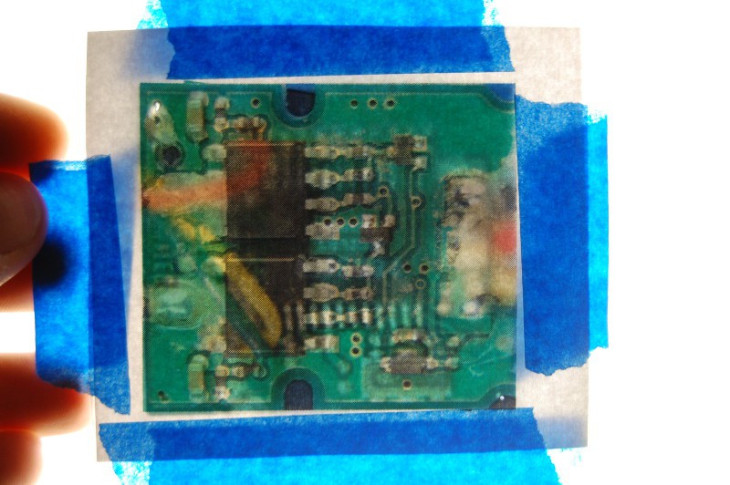
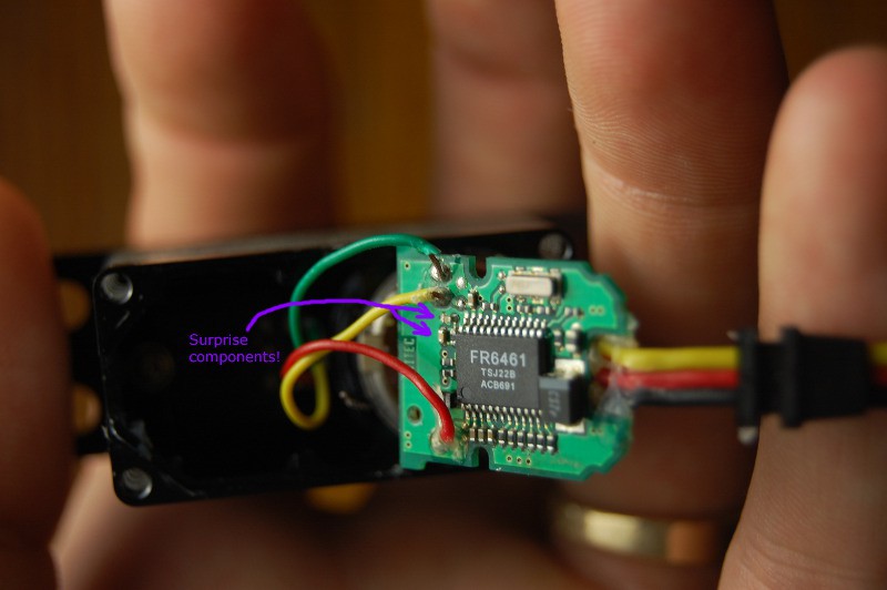
Probably not the best use of my time, but I built a nifty light source that should be handy for future photographs. In any case, I ended up spending quite a bit of time after the image manipulation bit with an X-acto knife, carefully scraping away the excess glue. Seems there are two types: hot melt, presumably to hold the board in place, and epoxy, used to strain-relieve the potentiometer and power/signal leads. I'll probably replace the former since I nicked 'em a bit, but I managed to reveal three (!!!!) hidden components:
Magnifying light + continuity tester + pictures + dinner + lots of screw-ups eventually produced this schematic:
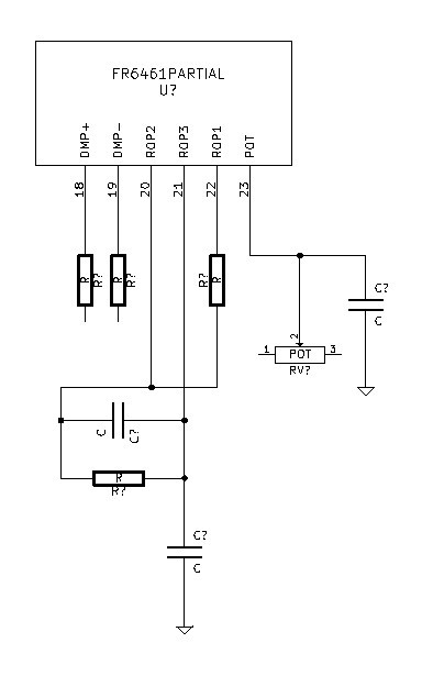
Seems fairly straightforward, I guess? In any case, it does seem to match the application circuit from the datasheet. Oh well, it was still a good exercise in reverse engineering.
Next, I combined the physically derived schematic with the FR6461 block diagram:
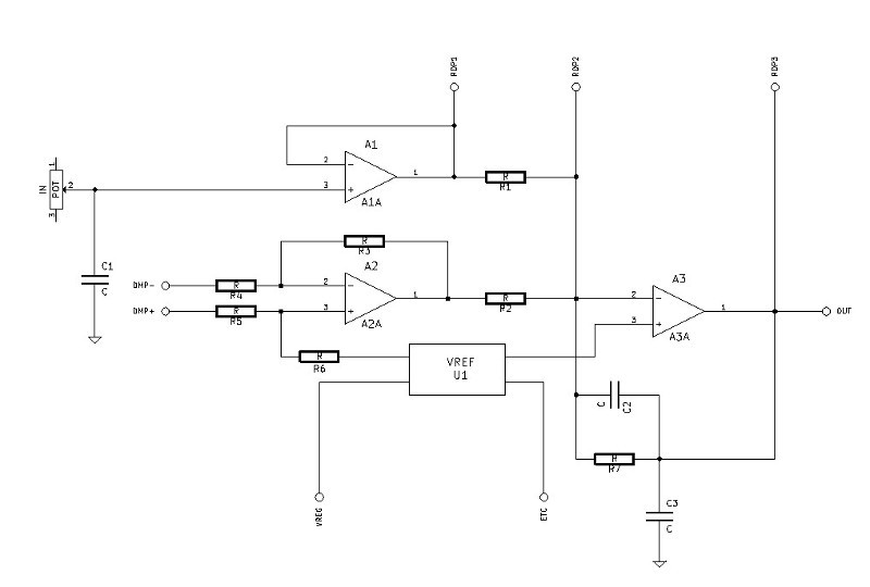
Sorry it's a bit tough to see the component numbers; I dumped the Kicad file as a Postscript, used a website to convert that to a *.gif, saved that as a *.jpg, and cropped/scaled it a few times (given all that rubbish, I'd say it turned out pretty well!). You can ignore the reference connectors; they just indicate where the IC pins line up. In any case, I think I can now compare this circuit to one sketched by Bob Pease in 1995 (he calls it figure 1), reproduced below:
 Still a bit of a mystery, I guess. I'm trying to find the Derivative band section, but from what I can tell those are always coupled to the main input using a capacitor. The only op-amp that has a capacitor on its input is A3, and that capacitor (C2) loops around as a feedback circuit. I suppose R7 (below C2) could be RF in Bob's sketch and C2 is the added 0.1 uF cap; but where is Cin?
I'm not ready to look at the answer yet; it's a bit past midnight on a weeknight, so I'm going to sleep on this one and give it some more thought after work tomorrow. Any more hints, K.C. Lee?
Discussions
Become a Hackaday.io Member
Create an account to leave a comment. Already have an account? Log In.
I guess A2 is really part of the P feedback loop and has the set point term some how. So if you were to decrease the gain from the feedback of the position, then the servo has compensate by moving a larger extend. That path is probably not too good. Need to restore the old resistor value between ROP1 & ROP2.
You can change the overall gain at A3 by changing the resistor connected across ROP2 & ROP3. Since the resistor ratios (hence gain ratios) from A1 & A2 are the same, the amount of servo swing should remain the same. Decreasing the resistor value would decrease the overall gain.
http://en.wikipedia.org/wiki/Differentiator
Decreasing the overall gain beyond some point would slow down the servo speed. When that happens, you might want to look at the differentiator by a R-C connected across ROP1 & ROP2. The series R limits the gain of the D term. This would temperory boost up the gain when the arm is moving. The RC time constant would have to be smaller than the amount of time between servo PWM pulses updates.
There is also the dead band digital setting - basically a range around the set point that the servo is insensitive to. http://en.wikipedia.org/wiki/Deadband
The external control loop from your microcontroller software would cover for the inaccuracy introduced.
Are you sure? yes | no
Or to look at it in a different way, if you were to short out the cap for the D branch, the two resistors would be in parallel. That parallel resistance would be equal to the old one. The C is there to boost he gain during the transient, but as the motor moves closer to the set point there would be less contribution, i.e. decrease overall gain/slow down. So less likely to overshoot.
Are you sure? yes | no
A1A is just a buffer for the position feedback signal. The resistance connected between ROP1 & ROP2 sets the P gain.
A3A is the summing node and c2 is part of the integrator. The resistor sets the overall gain of the system.
A2A is a difference amplifier. It is connected across the servo motor. Not entirely sure what it is doing other than providing voltage measured across the motor. Could be part of the error term as the input pulse is measured against the reference and stretched to drive the motor.??? The description does say for damping... Not like there is a whole lot you can do to play with the gain there.
May be the servo don't have a D term. i.e. just a PI controller.
So to not to have too much overshooting/damp your oscillations, you want to decrease the P gain and have the D fain make up for the difference. So comparing that with the figure 3 PID circuit in Bob's article.
http://electronicdesign.com/site-files/electronicdesign.com/files/archive/electronicdesign.com/files/29/6131/figure_03.gif
Looks like you could increase the value of resistor connected across ROP1 & ROP2 to decrease the P gain. Putting a series R+C as the D term and wired that between ROP1 & ROP2.
It would seem like your system is adding a lot of latency. Is adding a D term the best solution, I don't know. I am not too good with control theory.
Are you sure? yes | no
I think I might desolder R1 and measure its value to start with, then find a small trim pot that would cover that value at a fairly low point along its range. I've got enough room in the servo case that I could install it permanently between the circuit board and the potentiometer and putz around with the tuning with everything reassembled.
I was about to suggest adjusting the gain of A3A by changing the value of R3, then I realized that those particular components are internal to the chip. Right..
Are you sure? yes | no
Are you sure? yes | no
Are you sure? yes | no