 Eric Hertz
The basic idea is to increase the positional-resolution of an analog-output encoder by looking for *crossover* between various multiples of the input-signals... E.G. the first obvious crossover to detect is when channel A crosses over its inverse. In the thresholding-sense, this is equivalent to detecting when the sine-wave passes the halfway point. However, detecting *crossovers*, rather than thresholds, results in much better noise and calibration-immunity. Further, more crossovers can be detected than can be accomplished by merely thresholding each of the channels, by e.g. detecting for the crossover between channel A and channel B, or even channel A and -2 * channel B.
So far, anaQuad2x and anaQuad4x achieve 2x and 4x the resolution of a typical digital-output (or digital-thresholded) encoder's 4 steps per slot, giving 8 steps and 16 steps per slot, respectively. anaQuad6x and anaQuad8x are in the works to give 24 steps and 32 steps per slot.
Additionally, this same technique can be used for other locked-phase signals, such as two (of the three) 120-degree hall-effect sensors used on some BLDC motors.
An explanation of anaQuad's functionality follows the videos...
------------------------
(New: 3/11/16: Thoughts on using anaQuad as a communication-method similar maybe to LVDS 4/1/17: More thoughts in the latest log!)
Here's a video of anaQuad running at 4x, with a bit of functional-explanation.
From a 72-slot encoder, 1152 discernible positions can be detected per revolution.
And now, a computer-mouse's encoder, 48 slots -> 768 measurable positions.
This guy's a great (unintentional) test of the system's functionality despite somewhat dramatic calibration-error... The software's configured for a sine wave from 0 to 2.5V, (no software change from the previous experiment) and the encoder's outputting 1V to 3V (whoops), yet seems to be working surprisingly well.
I'm half-tempted to draw up a huge gauge, attach a long needle, and see just how much accuracy/precision I'm actually getting out of this.... and Done:
Maybe at some point I'll hook up my DC motor-positioning software and have a really big dial on the wall indicating something to fractional-degree resolution... (and to test the accuracy of that positioning-software despite things like the "snappy" action of motors intended for speed rather'n positioning, etc.)
An excessively-complicated galvanometer ;)
-----------------
Initial Thoughts: https://hackaday.io/project/9351/log/32010-quadrature-encoders-with-analog-output
Summarized:
Typically, the somewhat-sinusoidal outputs of the phototransistors are made square via comparators or Schmitt-Triggers.
Thresholding channels A and B

   _______         _ A-squared
  |       |       |
  | .-¯-. |       |
  |/     \|       |/
 -/-------\-------/---
 /|       |\     /|
A |       | '-_-' |
 _|       |_______|
  :.      :       :
  : . 90-degree phase-shift
  :  .    :       :
  :   ._______    :    _ B-squared
  :   |   :   |   :   |
  :   | .-¯-. |   :   |
  :   |/  :  \|   :   |/
 -----/-------\-------/
  :  /|   :   |\  :  /|
  : B |   :   | '-_-' |
  :  _|   :   |_______|
  :   :   :   :   :   :
  :   :   :   :   :   :
      0   1   2   3   0
      |<------------->|
      One encoder-cycle.
      Four Discernible Positions.
This method gives four discernible positions for each "slot" on an encoder's disk. So, e.g. if that old ball-mouse had 48 slots around the disk, then it probably measured 192 positions per revolution.An easy way to double that resolution is to look at crossover of the analog waveforms between the channels...
      Here
        |    And Here
        v       |
    .-¯-.-¯-.   |   A   B
   /   /:\   \  v  /   /
 -/---/---\---\---/---/
 /:  /: : :\  :\ /:  /
 -_-' : : : '-_-'-_-'
  :   : : :   : : :
  0   1 : 2   3 : 0
       1.5     3.5
  |<------------->|
  One encoder-cycle.
  Six Discernible Positions.
And to find the '0.5' and '2.5' positions, merely invert one channel and look for theappropriate crossover.
Crossover-detection is actually quite easy, based on the fact that we're watching every transition; we only need to check for *two* crossovers, rather than all those possible.
HAH!!!
I reversed A and B in this drawing!
(and likely elsewhere)
(A is usually represented by sin(x),
B by cos(x))
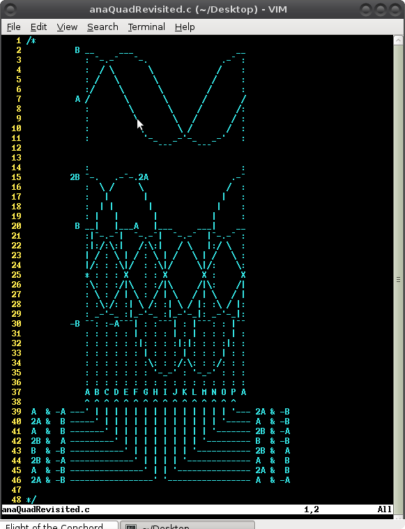
~B A B
.-¯-.-¯-.-¯-. ~B A B
B / /:\ /:\ \ / / /
X---/-:-X---\---X---/---/
~B \ /. :/:\: :\ /:\ /: /
A _-'-_-' : '-_-'-_-'-_-'
: . : : : : : : : :
H A B C D E F G H A
Say we're 'at' position A...
So, checking for either H or B...
B: Channel ~B crosses Channel A
H: Channel B crosses Channel A
We don't have to do too much here... knowing which transition happened recently, we look for two other transitions;from position A, it can either go to B or to H, depending on the direction.
From A -> B: channel A crosses the inverse of channel B: So test for A > ~BFrom A -> H: channel A crosses channel B: So test for A < B
From B -> C: cB crosses c~B: B > ~B
From B -> A: cA crosses c~A: A < ~A
... I'll leave the rest to you.
Then we have a switch() statement in an update() function:
switch(lastPhaseState)
{
 case PHASESTATE_A:
    //Advancing Right to B
    if( adcVal_A > INVERT_CHANNEL(adcVal_B) )
    {
       anaEnc_position++;
       lastPhaseState = PHASESTATE_B;
    }
    //Advancing Left to H
    else if( adcVal_A < adcVal_B )
    {
       anaEnc_position--;
       lastPhaseState = PHASESTATE_H;
    }
    //else, wait here...
    break;
 //From B -> C: cB crosses c~B:  B > ~B
 //From B -> A: cA crosses c~A:  A < ~A
 case PHASESTATE_B:
    //Advancing Right to C
    if( adcVal_B > INVERT_CHANNEL(adcVal_B) )
    {
       anaEnc_position++;
       lastPhaseState = PHASESTATE_C;
    }
    //Advancing Left to A
    else if( adcVal_A < INVERT_CHANNEL(adcVal_A) )
    {
       anaEnc_position--;
       lastPhaseState = PHASESTATE_A;
    }
    //else, wait here...
    break;
....
This system is tested-functional! Woot!
Resolution can be quadrupled by doing a tiny bit of math (this is now functional!).
Click "Read More" for quite a bit more!
The basic idea is to continue looking for crossovers, but instead of e.g. A and B and ~A and ~B, look as well for crossover between A*2 and B, etc....
And 8x resolution can likely be accomplished similarly.
(3/8/16: See log-entry on recent thoughts about 6x, using A, -A, 2A, and 4A).
Again, check out the full details of the above thought-process at: https://hackaday.io/project/9351/log/32010-quadrature-encoders-with-analog-output
Also check out the latest log-entry (a/o 3-6-16)
-------------------
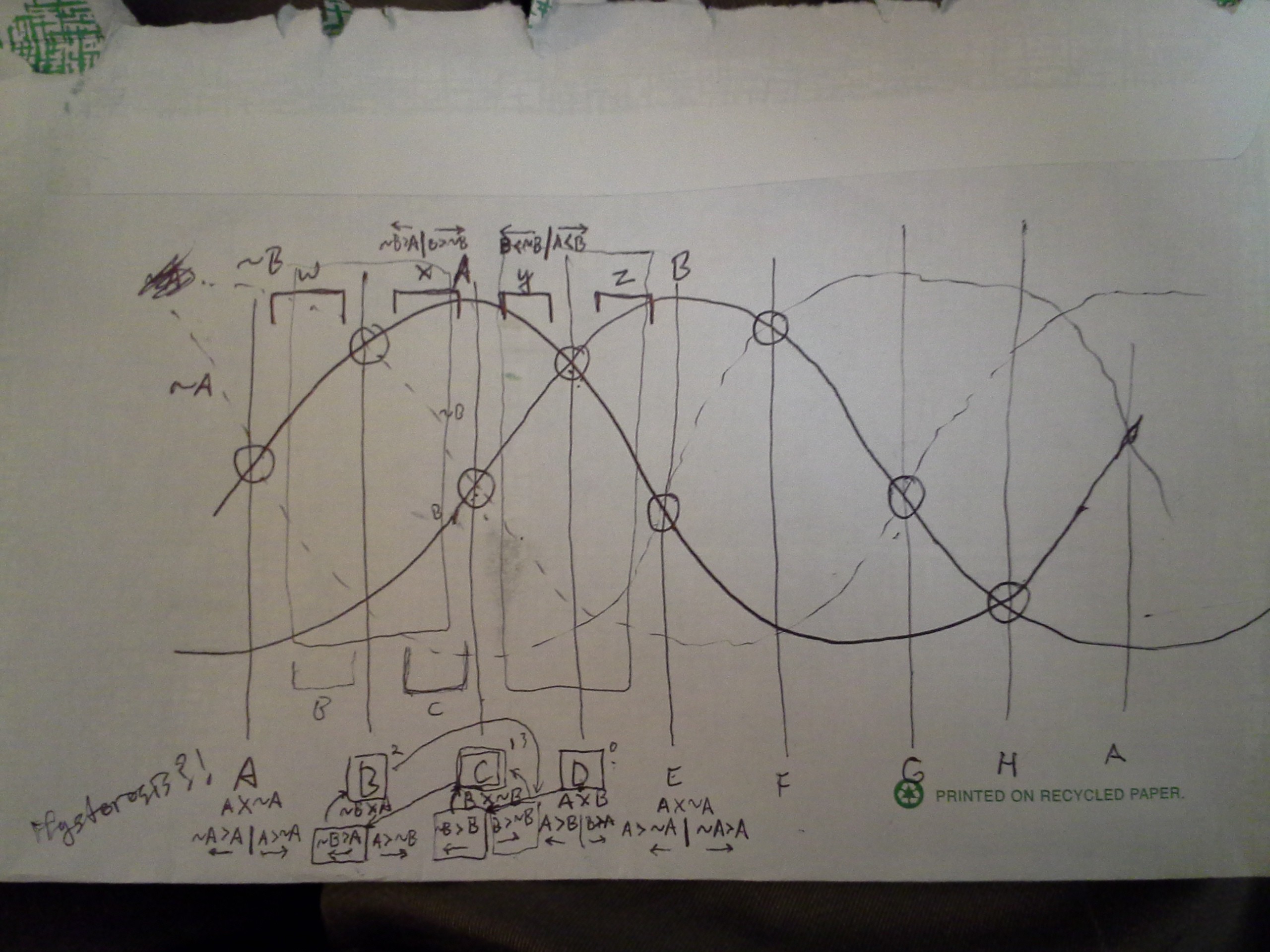
Some more thoughts on the matter: https://hackaday.io/project/9351/log/32681-anaquad-state-names-unintended-hysteresis
Summarized:
Interestingly, the methods described above (the switch-statement, as implemented) introduces hysteresis that I hadn't intended. So my quadruple-resolution system (now tested functional) likely has about twice as much positional-accuracy as a digital-quadrature system.
Doing it this way results in a bit of noise-immunity that I've deemed to be worthwhile... E.G. This should prevent any issues from the case where the encoder's output might be sitting at a crossover and bouncing back and forth between positions due to noise on the wires. Handy. Further, I think, detecting each intermediate position (without this 'hysteresis') would require keeping track of which direction it came from, increasing the instruction-count by a bit.
 Another interesting discovery of this switch-statement/crossover-detection method: It appears that the system doesn't actually have to catch every intermediate transition when they happen. As long as the update() function's phaseState is not more than half(?) a sine-period away from the actual position, the system should "catch-up" after a few more calls to the update() function. This is handy because it'd be pretty difficult to set some sort of interrupt to detect each transition at the moment it happens... So, instead, I have my update() function running in the main-loop, which might get bogged down from time-to-time while processing other things (like serial output). Similarly, it means that the system can be powered-up at any position and automatically figure out where it's at.
Again, the thought-processes of the above are at: https://hackaday.io/project/9351/log/32681-anaquad-state-names-unintended-hysteresis
-----------------
So, analog-output of phototransistors is great, but I wonder if this similar technique could be used with other systems... I've a vague idea about e.g. using a hard-disk platter-motor for position-detection... Some people print encoder-patterns to fit to make a homebrew optical encoder... e.g. for using the platter-motor as a "jog dial" for various purposes. But maybe the motor's electronics could be used with a bit of work... here's some thoughts on that: https://hackaday.io/project/9351/log/33074-anaquad-readytotest-magnets-effect-on-inductance
Or, another example would be that of e.g. a floppy-disk's spindle-motor, most of which have hall-effect sensors to detect the magnets' spinning 'round. Some hall-effect sensors have analog-output, so whereas the floppy-disk's motor may only have a handful of "poles" to detect, this crossover-detection system could increase the positional-resolution dramatically. Again, maybe a handy "jog-dial" or plausibly one of those wheels that people roll on the ground to measure distances...?
------------------
From what I've found, it seems some systems actually use sinusoidal-quadrature encoders for the very purpose of high-resolution, though my search-fu has resulted in little information on the techniques used. The best resource I've found, so far, is http://www.diegm.uniud.it/petrella/Azionamenti Elettrici II/Sensori e trasduttori/Data Sheet - 452913422000_sin_encoder.pdf
(It should be noted, the output of a mouse-encoder or any other for that matter, might not be *purely* sinusoidal. Some might be more triangular, or even trapezoidal... they're not designed with this in mind. The "crossover-detection" technique used in anaQuad should work even with these sorts of outputs).
The document linked above suggests two methods for detecting the position with exceptional resolution (way higher than 2x, 4x, or 8x described here). The first is using arctan to calculate the position using a bit of trigonometry and Pythagorean theory... This technique, in an ideal world, could result in resolution many orders of magnitude beyond anything my crossover-detection method could accomplish, and is probably well-suited for systems designed for this purpose. OTOH, if I understand correctly, it also inherently loses accuracy due to real-world factors such as electrical-noise, poor calibration, temperature, etc. And it introduces HUNDREDS of CPU cycles for *each* measurement (floating-point!). The second method described uses a feedback loop (which is a bit beyond my understanding) that requires up to 111 CPU cycles for each measurement.... But, again, the resolution increase is dramatically higher than the crossover-detection method described here.
With the crossover-detection switch() statement and a tiny bit of integer-math (I'm guessing, here) the number of executed instructions on a 32-bit integer-only processor should be somewhere on the order of 30 per measurement.
Sure, it requires a bit of pre-planning, and uses quite a bit of program-memory, but the actual number of executed instructions in each measurement is low. And now that 48-slot mouse-encoder could be bumped up to 768 (or more, soon?) measurable positions per revolution.
(Whether those measured positions are evenly-spaced is another thing, entirely ;)