Mrinnovative
Stepper-motor-synchronization

What is Stepper-motor-synchronization
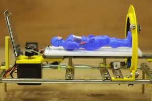
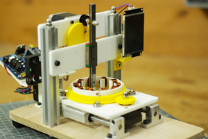
Stepper motor synchronization means we made physically, electrically & by programming a set for stepper motors which runs in perfect synch, in this system we have one master stepper motor and one slave stepper motor.
So the slave motor precisely follow the the moves of master stepper motor. They follow each other step by step. For this we have to program master and slave separately, the main point here is that we achieve this Complex motion by using only Arduino and custom PCB, not fancy PLC or controller needed. To achieve such precision we need our system also to be accurate for this Custom PCBs from JLCPCB.com really helps us.
Component used
- Arduino Nano
- Custom PCB
- NEMA 17 Stepper motor
- A4988 Stepper driver
- 20 x 20 alu. profile
- Right angle bracket
- GT2 belt
- GT2 pulley
- 8mm smoth rod
- 8mm linear bearings
- 3D printed parts.
Circuit
Power connections
This is the basic circuit by which we can control stepper motor via a4988 stepper motor The driver requires a logic supply voltage (3 – 5.5 V) to be connected across the VDD and GND pins and a motor supply voltage (8 – 35 V) to be connected across VMOT and GND. These supplies should have appropriate decoupling capacitors close to the board,
and they should be capable of delivering the expected currents (peaks up to 4 A for the motor supply).

Control inputs
Each pulse to the STEP input corresponds to one micro step of the stepper motor in the direction selected by the DIR pin. Note that the STEP and DIR pins are not pulled to any particular voltage internally, so you should not leave either of these pins floating in your application. If you just want rotation in a single direction, you can tie DIR directly to VCC or GND. The chip has three different inputs for controlling its many power states: RST, SLP, and EN. For details about these power states, see the datasheet. Please note that the RST pin is floating; if you are not using the pin, you can connect it to the adjacent SLP pin on the PCB to bring it high and enable the board.
By following such basics of A44988 we design a Custom PCB so that we not need to wire whole things again and again.
CUSTOM PCB


L293D = 2 pieces
LM7809 = 1 piece
LM7805 = 1 piece
10.1uF electrolytic = 1 piece
1N5408 = 1 piece
1N4007 = 1 piece
led = 1 piece
resistance of at least 470 Ohm = 1 piece
Arduino Nano = 1 piece
Oled display = 1 piece
Encoder = 1 piece
A4988 controller = 2 pieces
socket 8 + 8 = 1 piece
PCB female pin header connectors
screw connectors for printed circuit boards
I have design a PCB which is multipurpose and order it from JLCPCB
I always prefer JLCPCB.com for my PCB needs, JLCPCB.com have best deals for their customers $2 for 1-4 Layer PCBs, free SMT assembly monthly.
SMT Assembly service of JLCPCB.com is cherry on top now get your PCB fully assembled and save your time and money Select components for your PCB from there Parts Library of 200k+ in-stock components they are offering $27 valued New User coupon & $24 SMT coupons every month $8.00 setup fee, and $0.0017 per joint
Now no need to order components separately for you PCB and get free from stress of soldering them on PCB just try PCB SMT assembly service and get you PCB with components pre assembled and ready for the project
👉 Try PCBA service of JLCPCB.com and save your time and money, get PCB ready for project, 200K+ components in library of JLCPCB.com as well as 3rd party parts to choose from. Assembly will support 10M+ parts from Digikey, mouser
👉 $27 valued New User coupons
👉 $24 SMT coupons every month
For more detials & offers please visit JLCPCB.com
Click here to visit JLCPCB.com


First of all I take some 20 x 20 aluminium profile, and make the base of the machine out of it. I used right angle bracket to joints the corners.


Then I bring 2 8mm SS smooth rod. And...
Read more »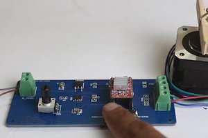
 Frank Herrmann