 Mitsuru Yamada
1. Concept
As a practical application of my PERSEUS-9 computer for astronomical observation, I decided to create a hardware and software system to display the celestial coordinate system of an equatorial mount. This computer is not suited to perform a large amount of processing at high speed because of its 1970s processing speed. Therefore, instead of controlling the mount from the computer side, the PERSEUS-9 reads and displays control status of the controller. From the button operation of the hand controller to the counting of motor drive and drive pulses, the system is configured with homemade hardware MCT-6. The count values are converted to angle values in right ascension (R.A.) and declination (Dec.) by CI-2, a homemade floating-point interpreter for PERSEUS-9, and displayed in real time. No automatic GoTo action or polar axis correction from the computer side is performed. Figure 1 shows the MCT-6 and the computer PERSEUS-9, and Fig. 2 shows the homemade equatorial mount.
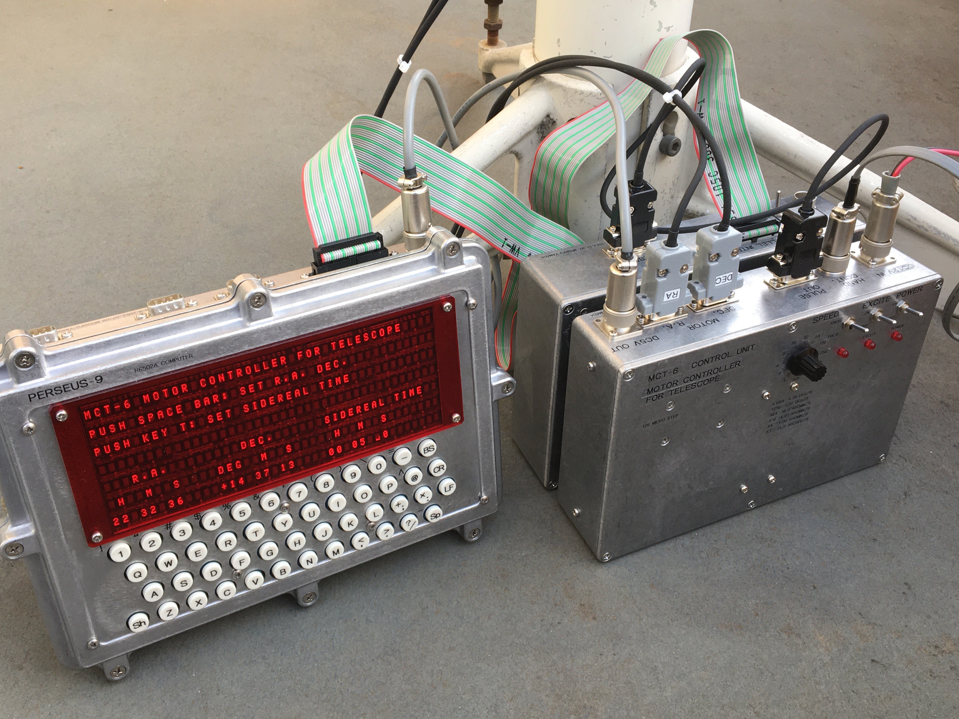
Fig. 1 MCT-6 the telescope mount controller and PERSEUS-9.
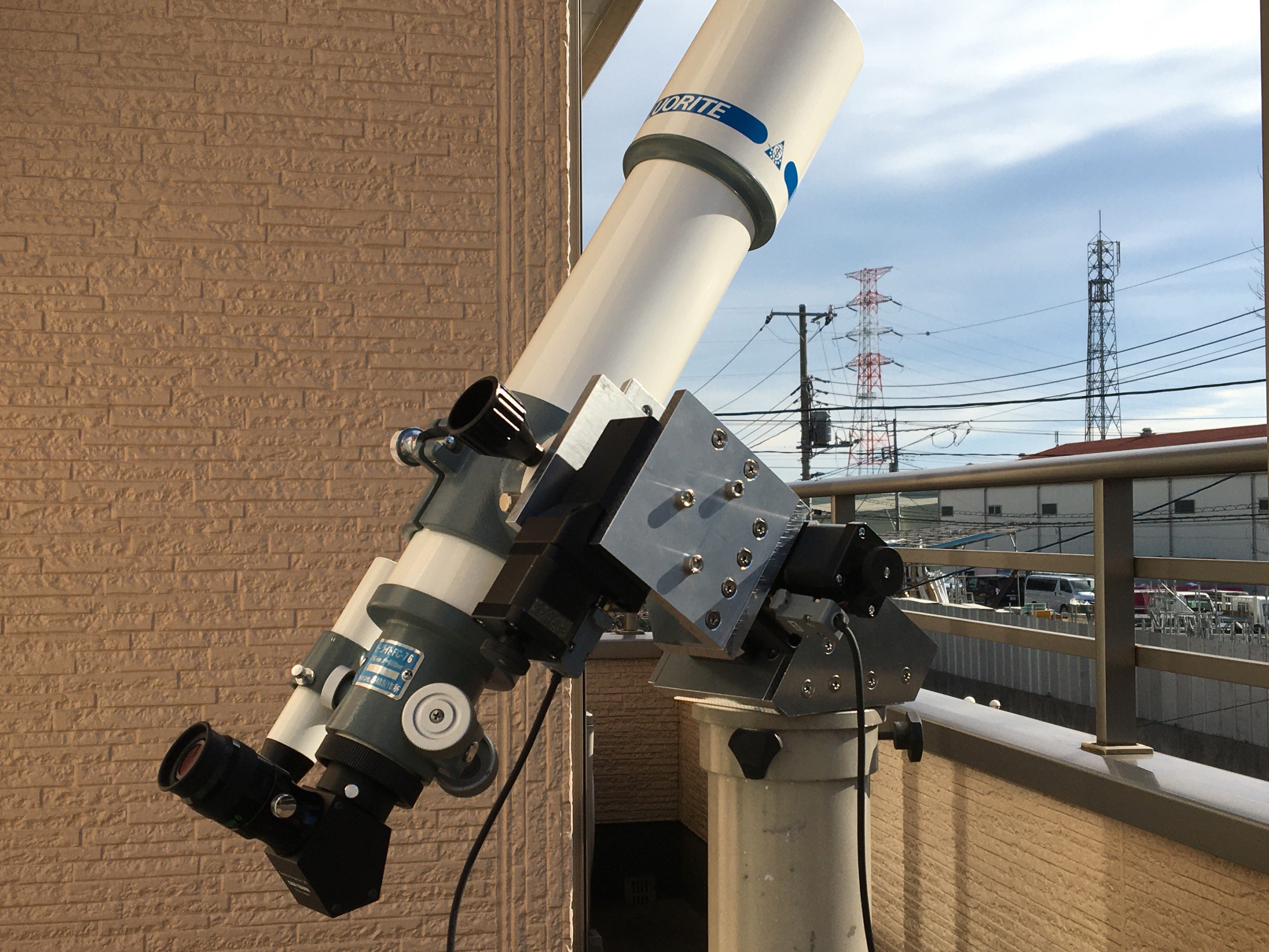
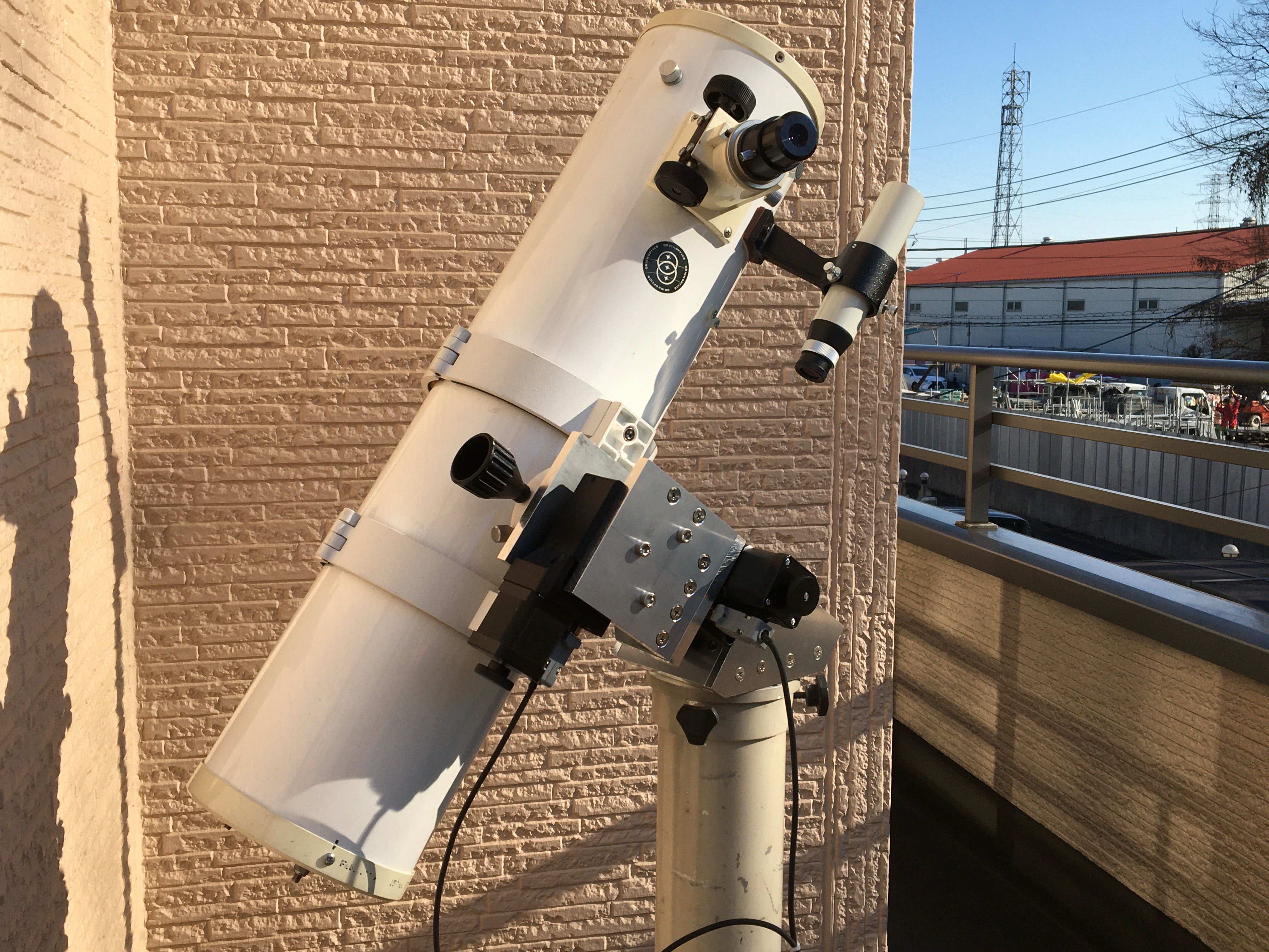
Fig.2 Homemade telescope equatorial mount with a 7.6cm refractor optical tube.
2. Equatorial mount
Another major challenge for me in this project was to build an equatorial mount that would be practical for my own visual observations. An equatorial mount has two orthogonal axes, one of which is the R.A. axis, which is parallel to the earth's axis of rotation. The R.A. axis rotates once every 24 hours, 56 minutes, and 4 seconds, which means that the telescope can automatically track a fixed star. This is known as tracking diurnal motion. Assuming that the telescope's observation resolution is about 1 arcsecond in angle, the vibration during tracking must be kept to less than a fraction of that in order for the star not to appear shaky. On the other hand, if the telescope is moved in a different direction to slew another object, the speed must be several hundred times higher than the tracking speed.
There are difficulties in satisfying these two conditions simultaneously. For example, if such a speed change is achieved using a normal stepper motor drive system, the step period during diurnal motion tracking will be about once per second of time or once every 15 seconds of angle, and the tracking image will appear to shake violently. Therefore, if a micro-step drive method that divides the stepper motor steps into smaller steps is used, it is possible to perform fine driving of several tens to several hundreds of steps per second even during tracking. In this way, a drive system with sufficiently reduced vibration is generally constructed.
It has also been difficult for me to prepare mechanical elements such as shafts, bearings, and worm gears that can withstand a certain amount of moment. So this time, I decided to see if I could solve this problem by using a commercially available motorized rotary stage. This motorized rotary stage is used for optical experiments and industrial applications and is expensive, but recently I found that it is available at a relatively low price through a certain mail-order site. Figure 3 shows the appearance of the motorized rotary stage used. This motorized rotary stage has a 60 mm diameter rotating part, and a 200 P/R stepper motor directly connected to a 90:1 worm gear. Both sides of the stage can be connected to other structures with M5 and M6 bolts.
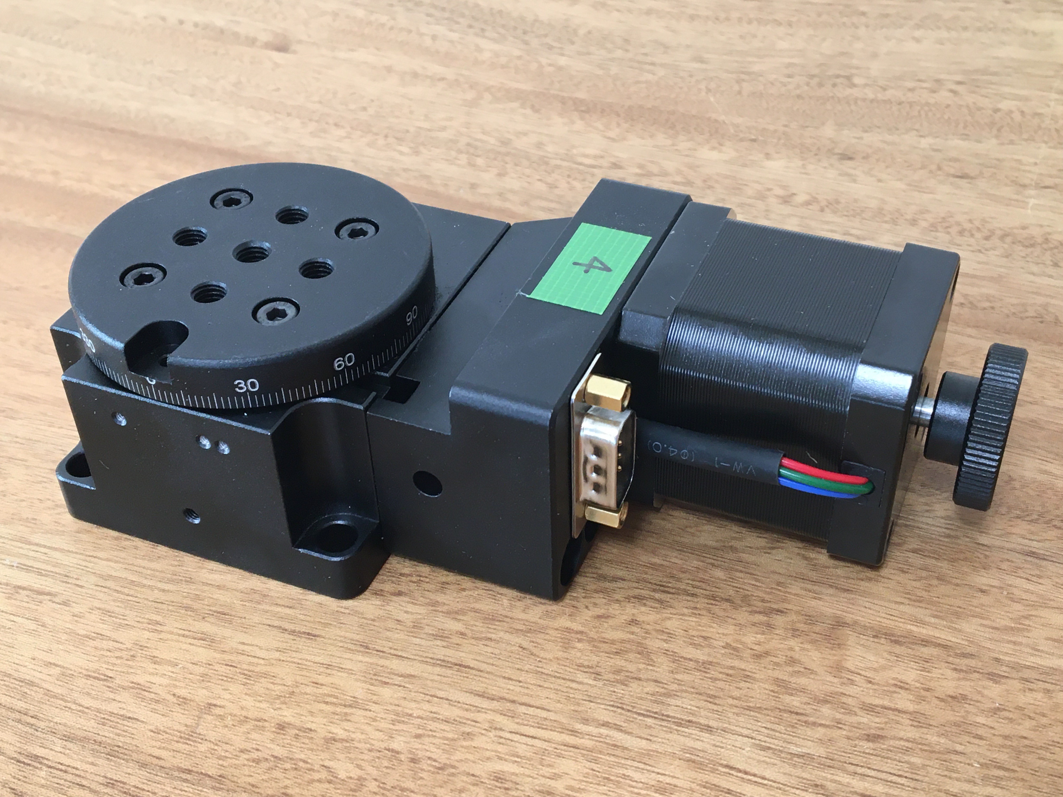
Fig. 3 Motorized rotary stage Y200RA60.
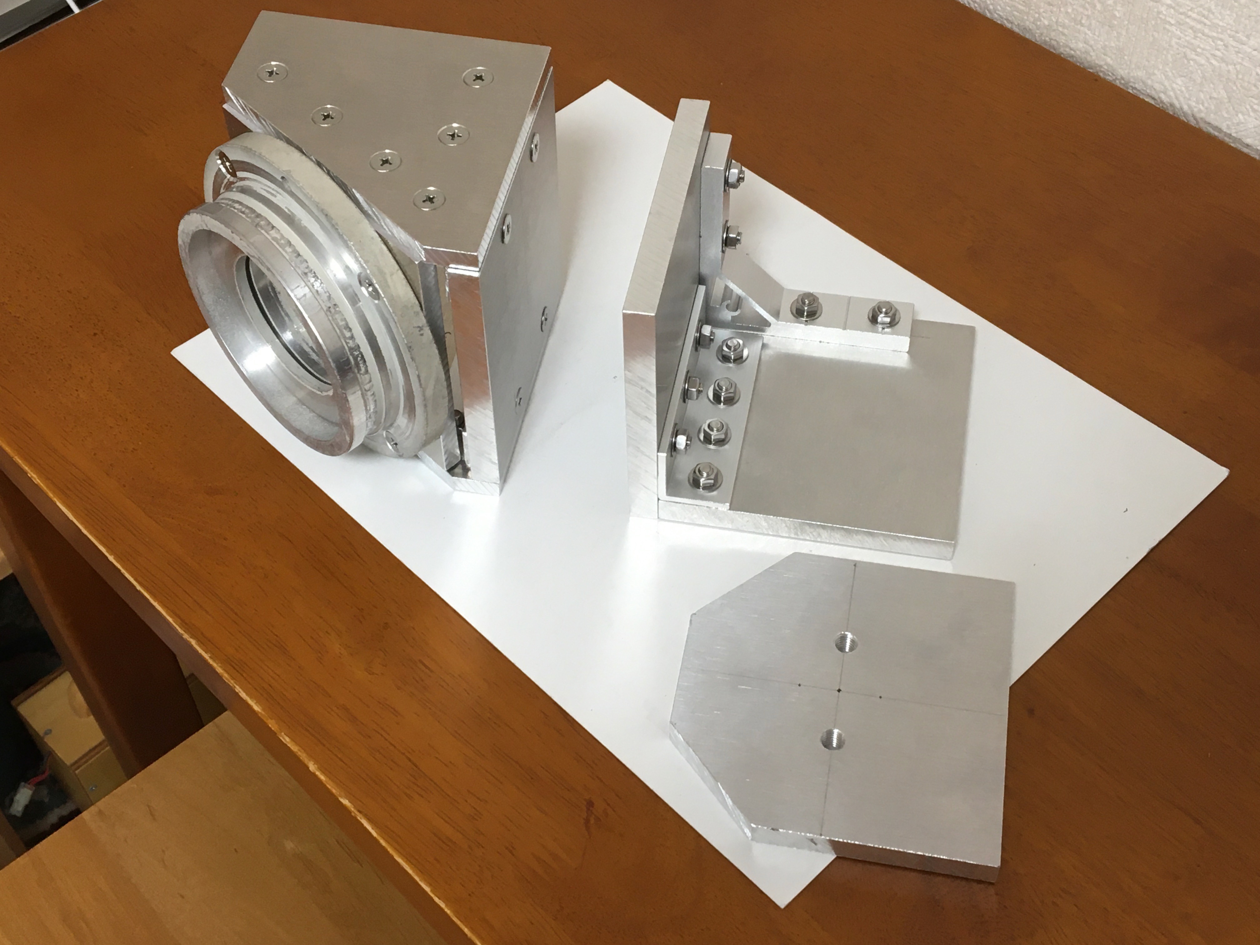
The appearance of the self-made equatorial mount is shown in Fig. 4. The structures on the equatorial mount other than the rotation stage were made of 100mm x 100mm, 10mm and 7mm thick aluminum materials that were machined and used. On top of the pillar connection body, the rotation stage of the R.A. axis is fixed to the face of the aluminum material, which is assembled to be perpendicular to the latitude value. On the rotary stage of R.A. upper surface, an L-shaped Dec. axis body is fixed. And a rotary stage of Dec. is fixed to Dec. axis body. The optical tube is fixed to the top surface of the Dec. rotary stage via a standard dovetail adapter for telescopes. There is no manual coarse movement mechanism to free the gear. The length of the arm of the Dec. body is shortened for strength and vibration considerations, so the optical tube cannot be oriented to the northern sky above 45 degrees of Dec.
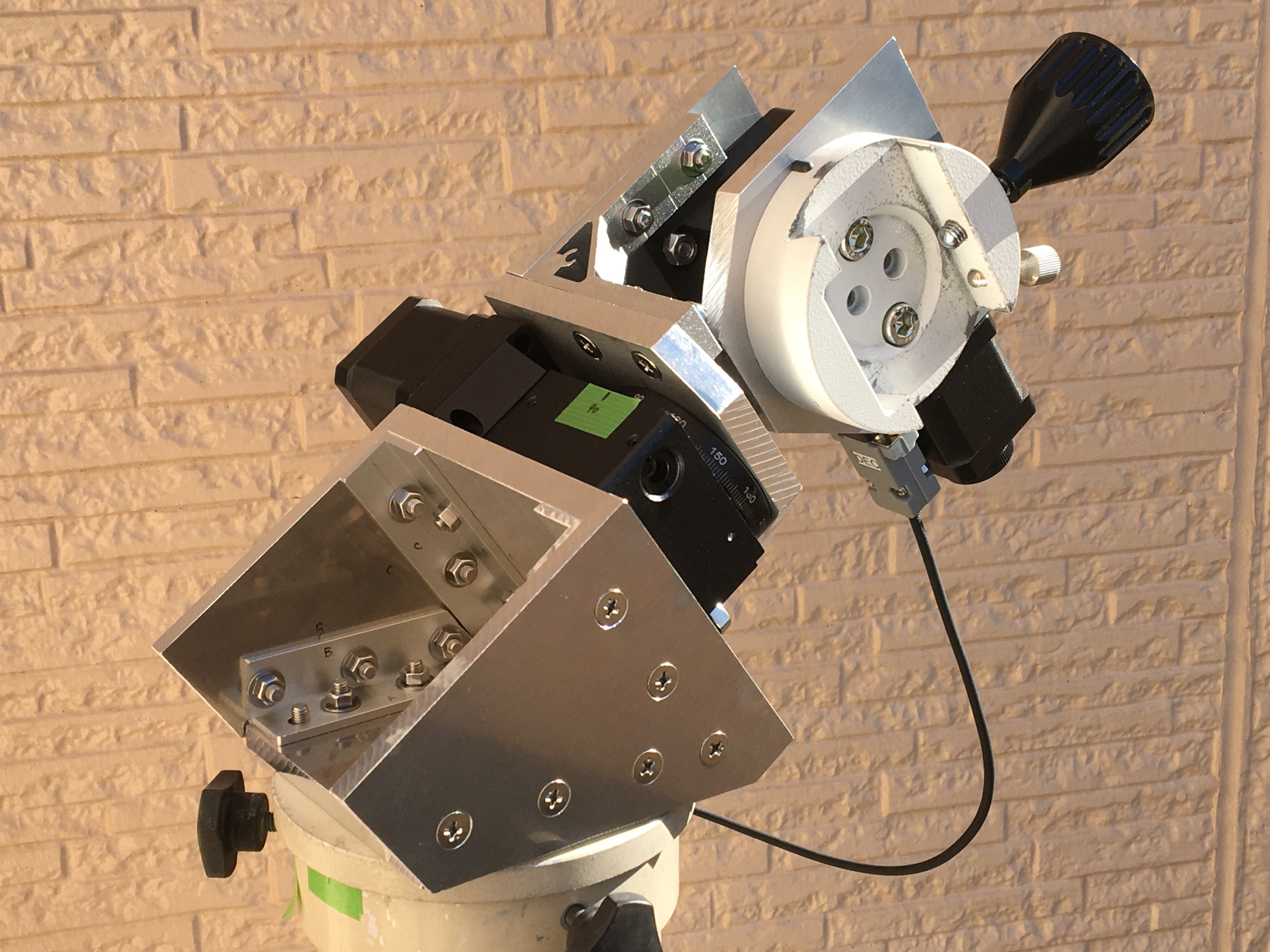
Fig. 4 Homemade equatorial mount.
3. Control unit
Figure 5 shows a block diagram of the MCT-6. The hardware consists of a control unit and a counting unit. The control unit is controlled by buttons on the hand controller and has a pulse signal generator for diurnal motion tracking and slewing, and microstep drivers for driving the stepper motors. And the control unit does not use a CPU, but consists of standard logic ICs. If the display of R.A. and Dec. coordinates is not necessary, this unit alone can be used to operate the telescope with the buttons on the hand controller. The counting unit counts pulses during tracking and slewing and interfaces to the computer PERSEUS-9.
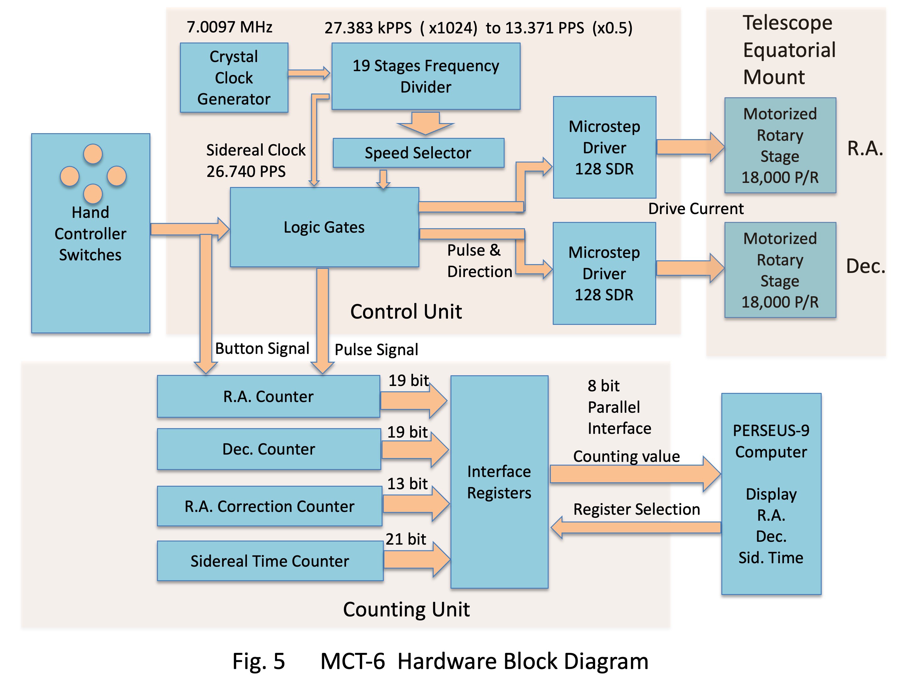
The crystal oscillation frequency for diurnal motion was calculated as follows. Since the rotation stage is 18,000 P/R and the number of microstep divisions is 128, the pulse to make one rotation of the stage in 23 hours, 56 minutes, and 4 seconds is 26.740 PPS. Here, I found that a crystal oscillator of 7.01 MHz in the amateur radio frequency band, divided by 18 stages, is very close to this value. The frequency is adjusted to the ideal value of 7.0097 MHz by adding a trimmer capacitor in series with the quartz crystal. Pulses for slewing are switched by a rotary switch from the signal in the middle of this frequency dividing stage. The speeds from 0.5x to 1024x with respect to tracking diurnal motion can be used with this system. Originally, motor-driven acceleration/deceleration requires a trapezoidal acceleration with a gradual change in speed, but this is omitted here to simplify the circuit. Figure 6 shows the control unit circuit.
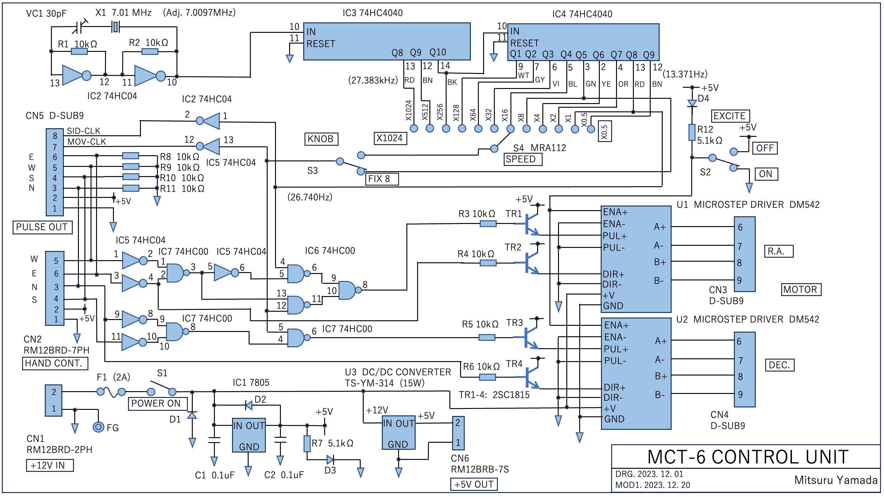
Fig. 6 MCT-6 control unit circuit.
In the control unit, the gate circuit is configured so that when none of the hand controller buttons are pressed, the motor driver of the R.A. axis is fed a pulse of 26.740 PPS and pulses for slewing is fed while the E or W button is pressed. The motor driver for the Dec. axis is fed pulses for slewing when the button N or S is pressed, and does not fed pulses for the rest of the time. The microstep driver unit is a commercially available DM542 type. Figure 7 shows the inside of the control unit. Figure 8 shows its exterior. The enclosure is a Hammond 1550G, with external dimensions of 220 mm x 146 mm x 55 mm.
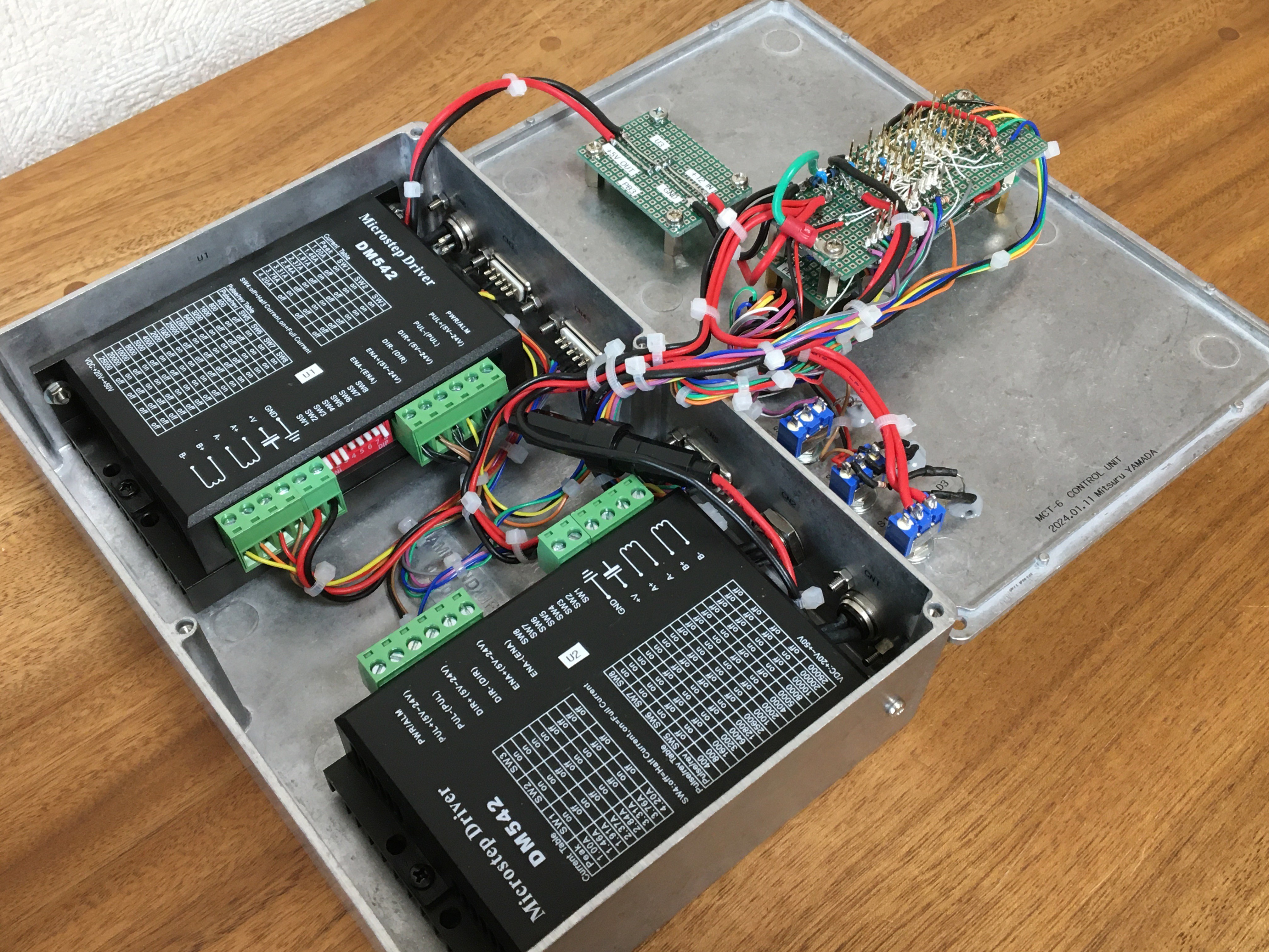
Fig. 7 Inside of the control unit of MCT-6.
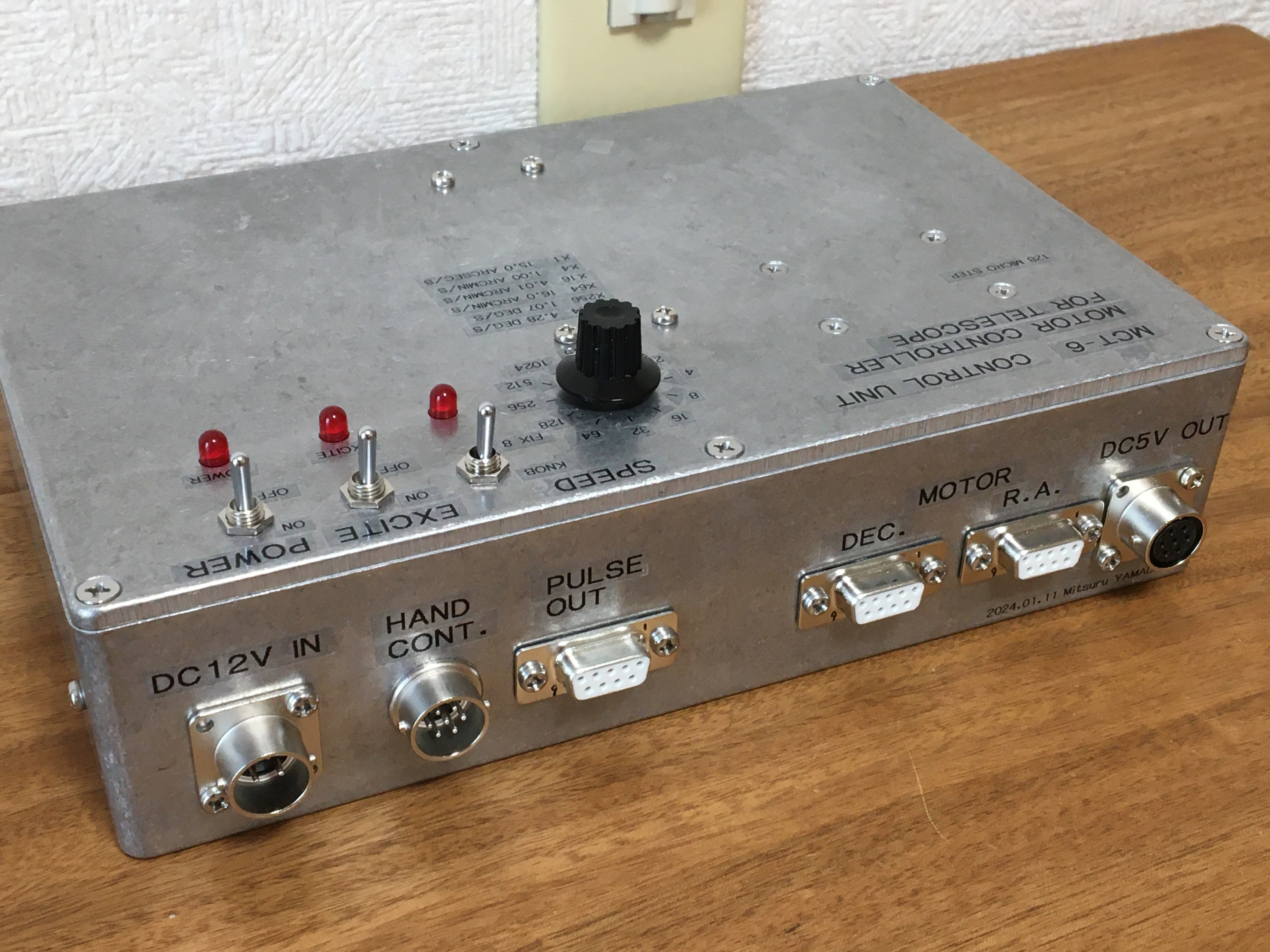
Fig. 8 Exterior of the control unit of MCT-6.
4. Counting unit
The counting unit has an up-down binary counter for counting R.A. pulses, an up-down counter for counting Dec. pulses, an R.A. correction counter, and a sidereal time counter for counting sidereal time, as shown in the lower half of Fig. 5. The circuit for the pulse input and the R.A. counter portion is shown in Fig. 9. The other circuit parts are shown in the attachment. Since the sidereal time continues to progress during the slewing of the R.A., errors accumulate in the R.A. if only the count value of the slewing pulses are used. To prevent this, the R.A. correction counter is used. The correction of the R.A. value is not done by hardware, but by software after the readout by PERSEUS-9.
The counter is configured with standard logic up-down synchronous counter ICs 74HC191 as shown in Fig. 9. A synchronous counter is used instead of a ripple carry counter to prevent the count value from being shifted during readout. During readout, a hold signal from the parallel interface of the PERSEUS-9 is used to hold the value in the registers 74HC374 all at once. The value is then read out while switching registers.
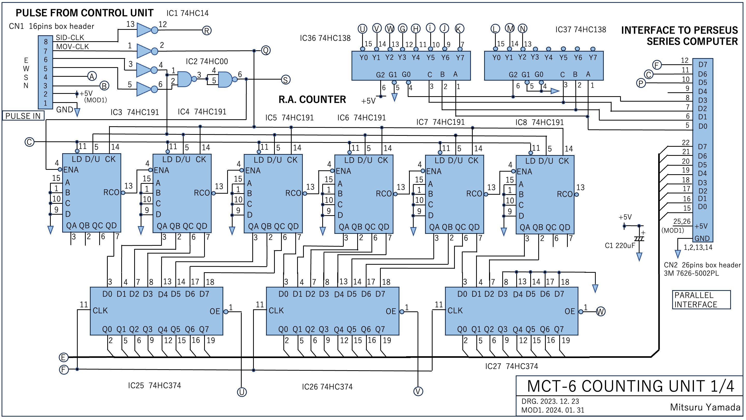
Fig. 9 The circuit for the pulse input and the R.A. counter of MCT-6 counting unit.
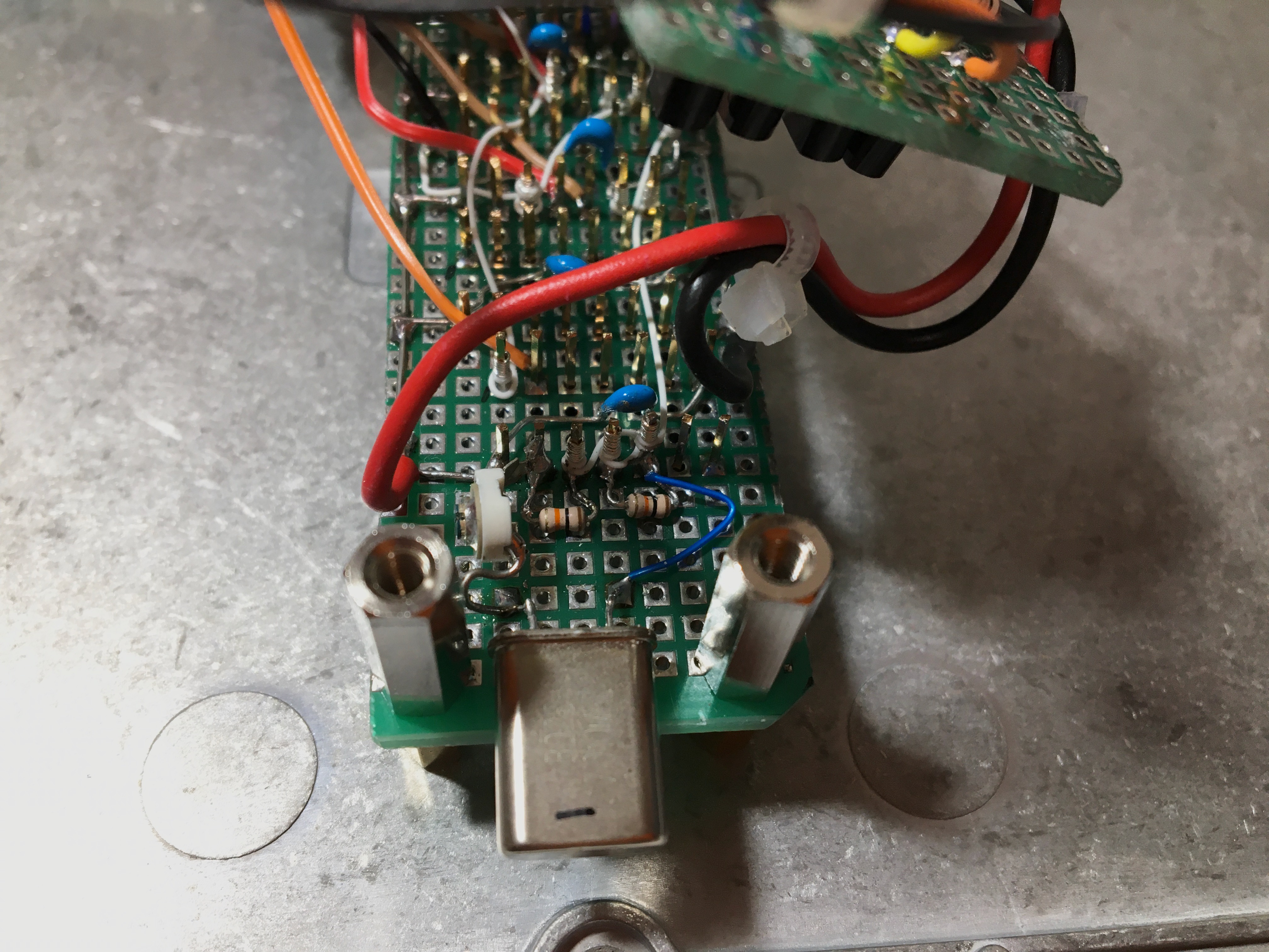
Figure 10 shows the circuit board of the counting unit using a universal board. Figure 11 is its wiring side. Wiring was done by wire wrap.
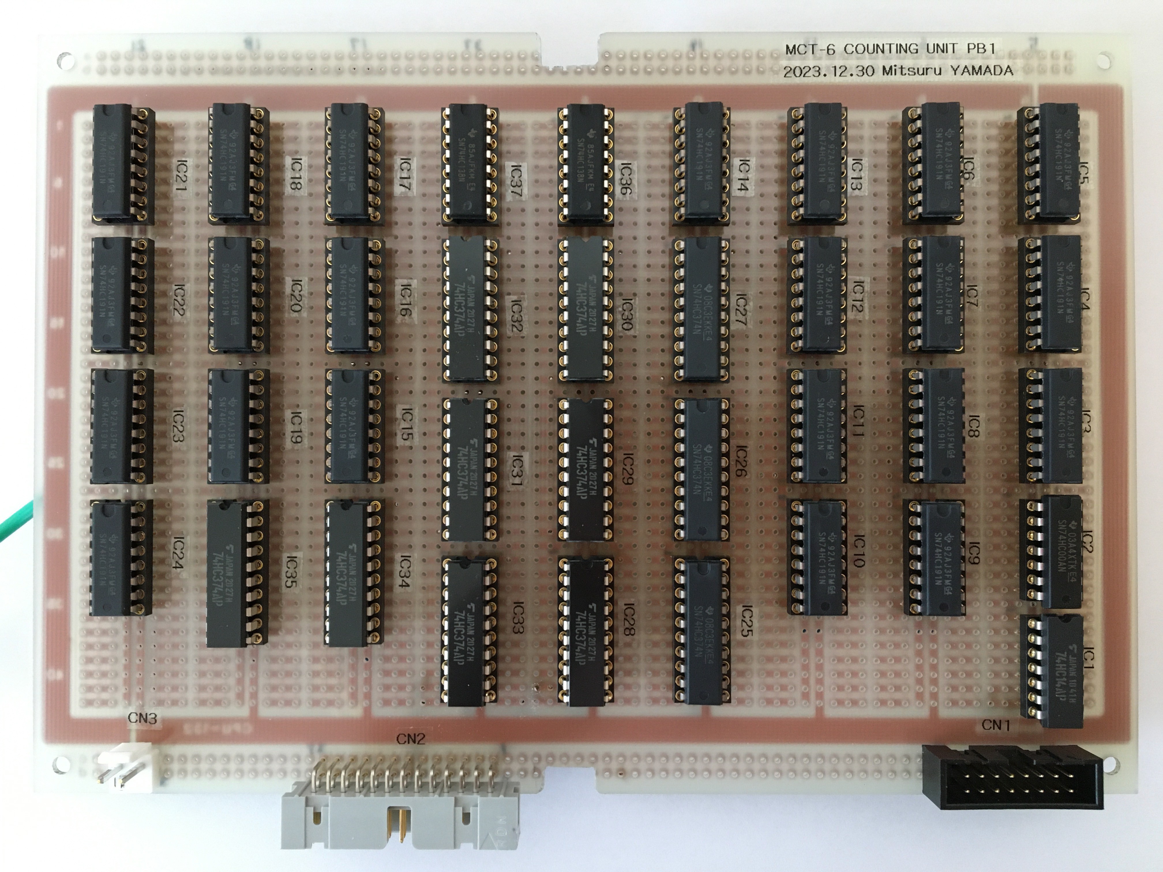
Fig. 10 Circuit board of the counting unit of MCT-6.
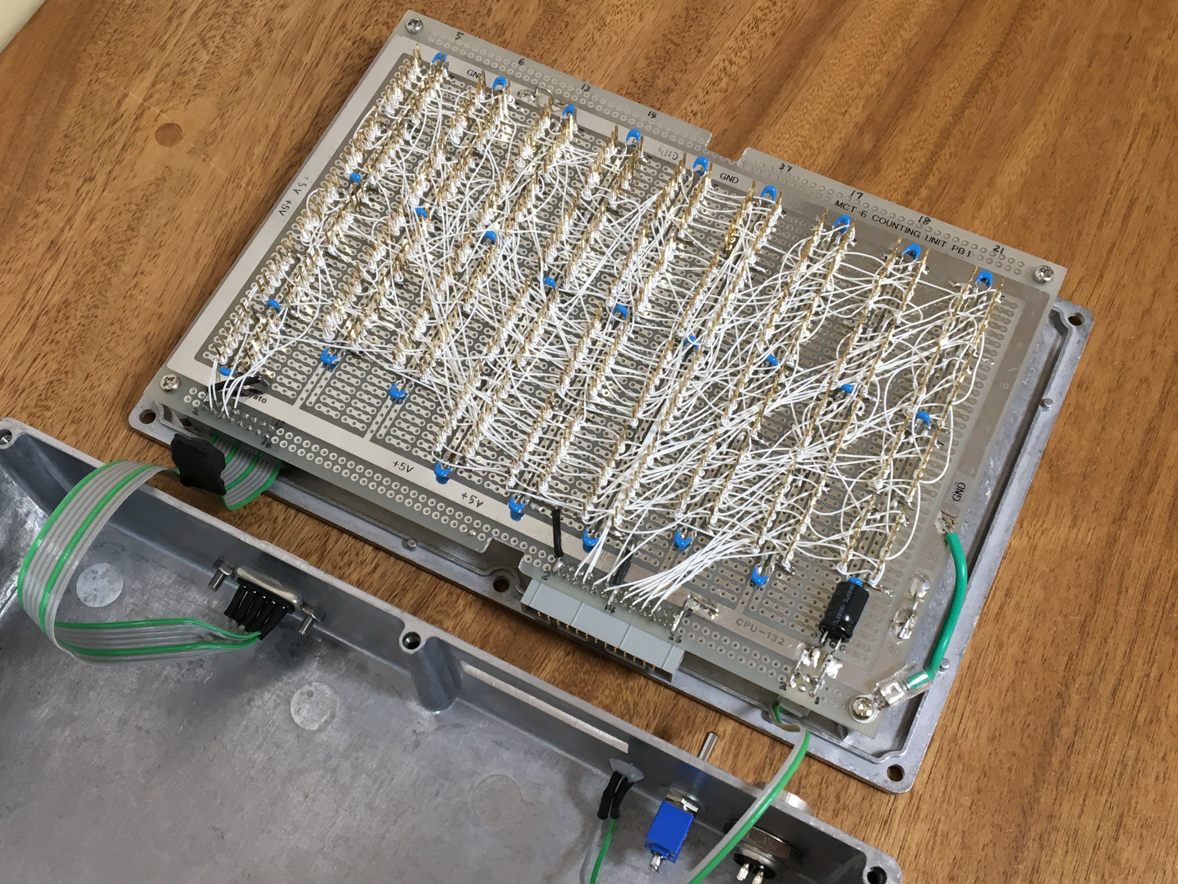
Fig. 11 Wiring side of the counting unit circuit board of MCT-6.
Figure 12 shows the appearance of the counting unit. The enclosure uses the same Hammond 1550G as the control unit.

Fig. 12 Exterior of the counting unit of MCT-6.
5. Display software with PERSEUS-9
A flowchart of the software processing in PERSEUS-9 is shown in Fig. 13. The process was written as a user program 'DISP_ANGLE_21.TXT'of CI-2, a home-made floating-point interpreter.
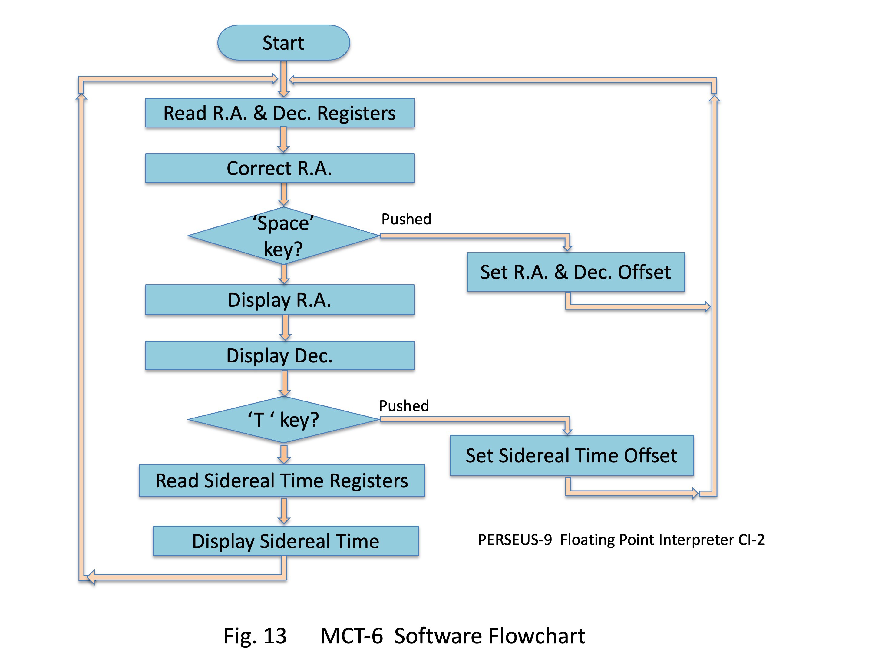
Floating-point variable values are generated by weighting the readout values of the 8-bit parallel interface by 65536, 256, and 1. The R.A. and Dec. count values are in two's complement format. Here, the R.A. correction count is added to the R.A. count value. The R.A. and Dec. are set to 19 bits so that they will fit into the six significant digits of the CI-2 variable mantissa part specification after conversion to decimal numbers.
When the space bar on the keyboard is pressed, the alignment values for R.A. and Dec. can be input from the keyboard. The input values are added to the RA and Dec. counts respectively as offset values. If the R.A. exceeds the range of 0:0:0 to 23:59:59, a correction calculation is performed to keep it within that range.
The conversion and display of decimal values into R.A. and Dec. in base 60 is done by a process of dividing the variable by the weighting of each of its digits. Furthermore, the CI-2 currently cannot control the number of digits displayed for variables, so the ASCII code corresponding to each digit of the displayed value is sent to the serial interface. The current program has 294 lines and a capacity of 5.4 kB. Figure 14 shows the display status on PERSEUS-9.
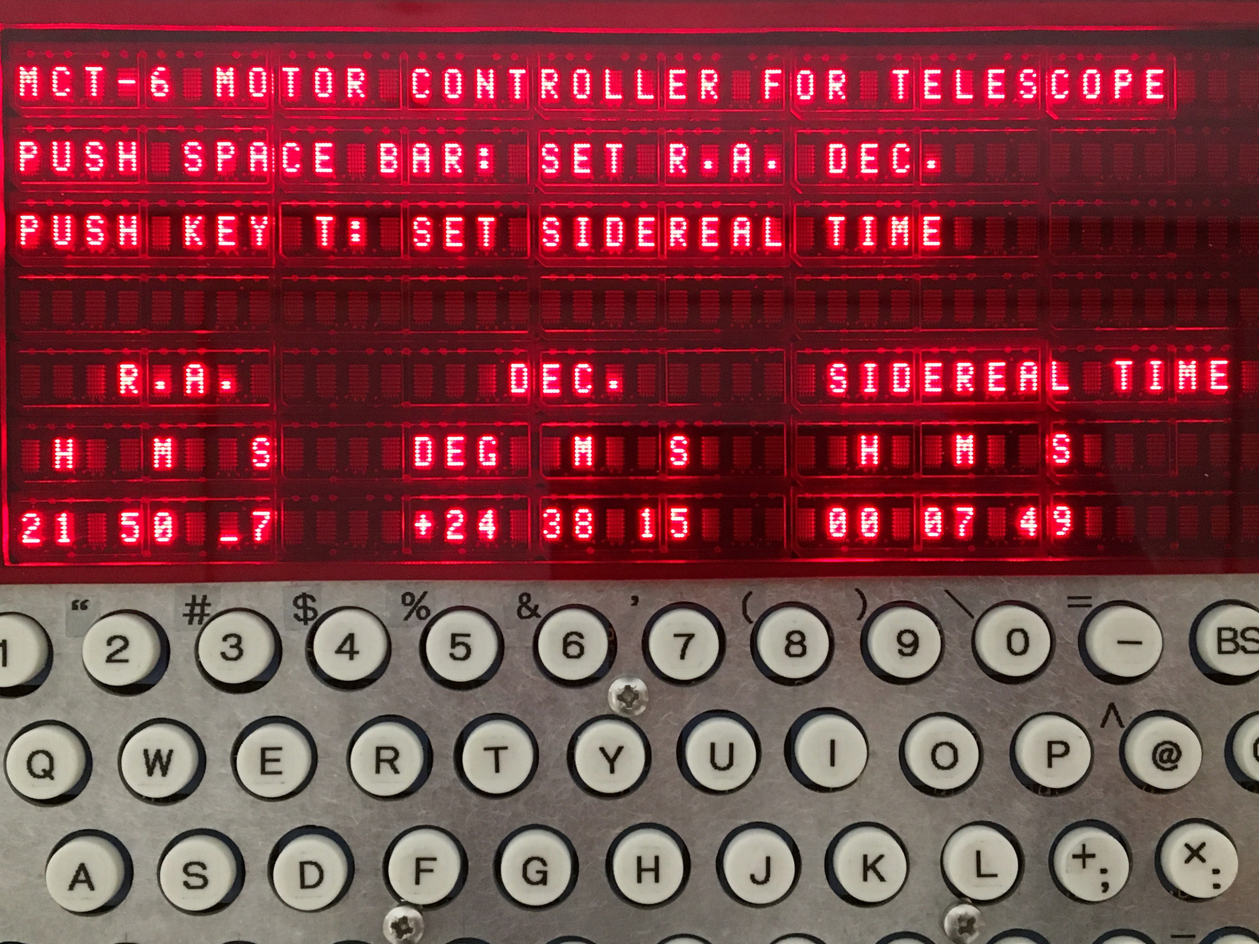
Fig. 14 R.A., Dec. and sidereal time display status on the PERSEUS-9.
Figure 15 shows the motorized rotary stages connected to MCT-6 and PERSEUS-9 for operation testing.
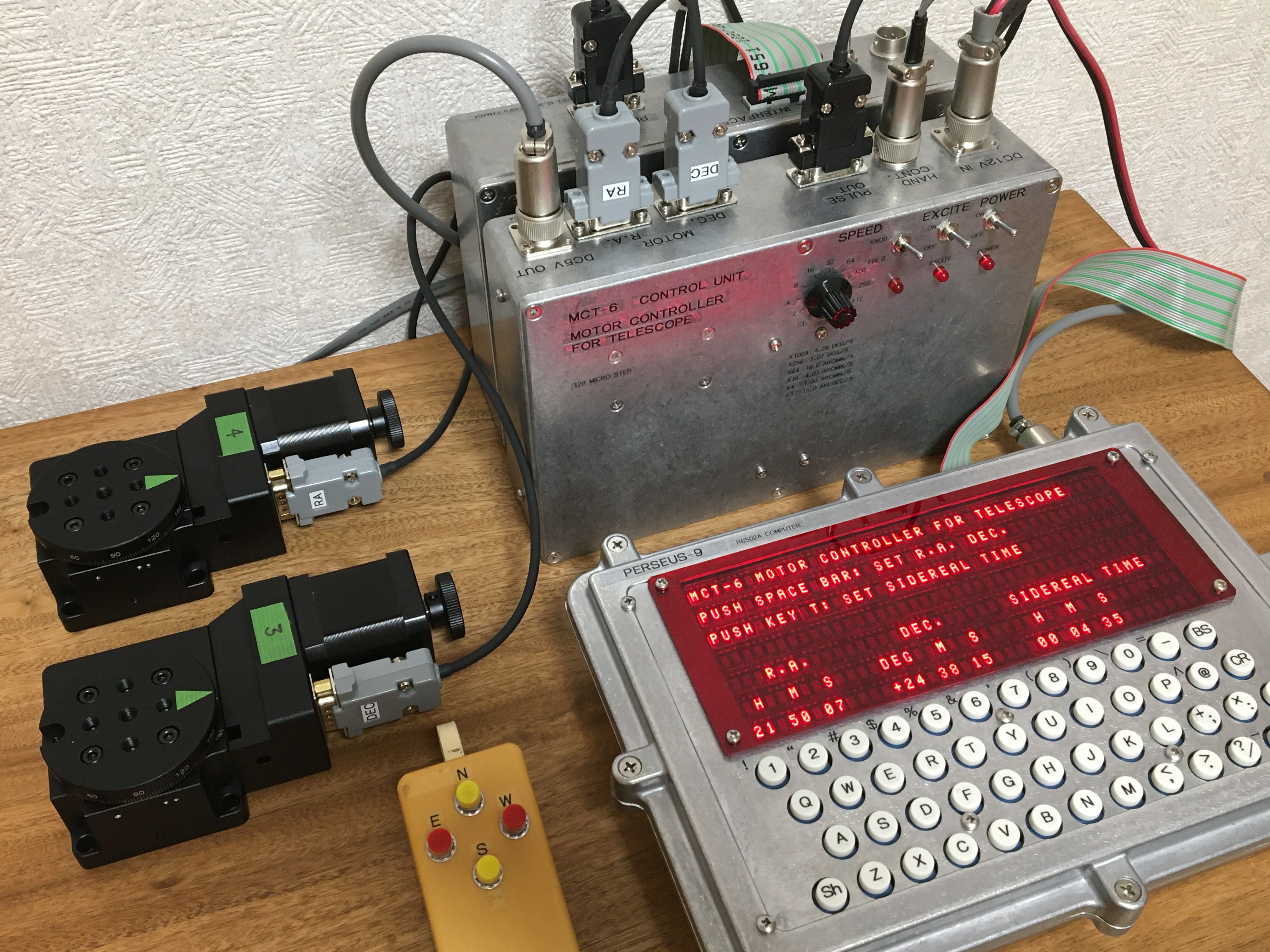
Fig. 15 Motorized rotary stages, MCT-6 and PERSEUS-9 for operation testing.
6. Result
At first, I tried using a 32-division step microstep driver to drive the motor at a pulse rate of 6.7 PPS, but the mount with a telescope oscillated at an angle of about 1 second, making it impractical for visual observation at 200x magnification due to the constant image vibration. As a countermeasure, the microstep driver was changed to a model DM542 with 128 steps, and no image oscillation was observed even under visual observation at 200x magnification. The following Table 1 shows an example of the display error of R.A. and Dec. evaluated by actually introducing fixed stars to the center of the field of view. First, Jupiter was introduced at the center of the field of view and aligned with the values of R.A. and Dec. As shown in the table, the smaller the displacement from the alignment position, the smaller the display error. In the current evaluation, the error is about 1% of the amount of movement.
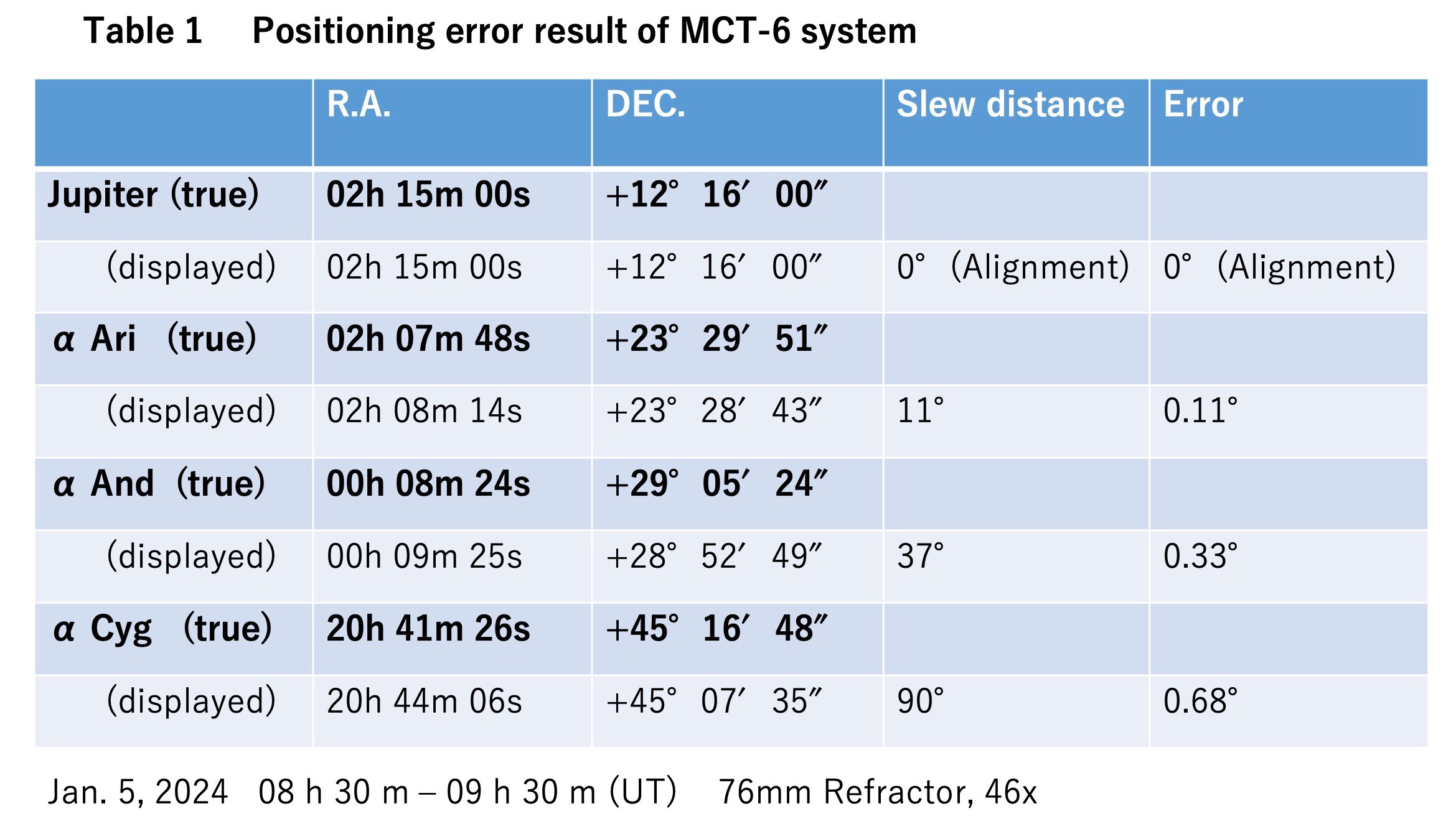
The cause of this error is thought to be a combination of factors such as misalignment of pulse counts and rotational position due to motor step-out, gear deviation, orthogonality of the telescope optical axis and polar axis, orthogonality of the mount's R.A. and Dec., and polar axis tilt and east-west misalignment. If, after alignment of the R.A. and Dec. values by using a star at an angular distance to about the next constellation, the target object can be introduced into the field of view with an observation magnification of about 50x if the displayed value is moved with a button operation until it reaches the value of the target object.
The display update rate for R.A., Dec. and sidereal time in PERSEUS-9 is 1.1 times/s. I tried to reduce the number of program lines by subroutining similar processing parts in the program, but this was not applied because the update rate became even slower due to the subroutine call processing in the interpreter.
The maximum payload weight of this equatorial mount is about 5 kg. For a short optical tube of about 40 cm in length, moving at 1024x speed does not cause abnormal vibration noise, but for a long focal length optical tube with a large moment, it was necessary to limit the moving speed to 512x or 256x speed.
The power consumption of the controller unit and motors, excluding the PERSEUS-9 and counting unit, was 7 W (12 V, 0.6 A). Most of this power was consumed by the microstep controller and motors. The counting unit consumes about 10 mW.
7. Summary
As described above, the equatorial mount of the astronomical telescope has been built by myself by incorporating a motorized rotary stage, and the MCT-6 including its control unit and counting unit has been also built by myself. The display of R.A. and Dec. was realized with a self-made computer, PERSEUS-9. I will continue to evaluate and improve the display error and processing. The following video shows the inside of the MCT-6 and how the telescope mount is controlled. This video does not have audio commentary, so please turn on subtitles.
VIDEO 1 Introduction of MCT-6.
(Posted on Jan. 21, 2024)
(Rev. May. 16, 2024)