Close
0%
0%

Integrated HUB - Ethernet, USB, RS232

Swiss Army Switch - Ethernet Switch, USB HUB, USB-Ethernet and USB-RS232 Adatper

Similar projects worth following
388 views
I frequently use a (1) USB HUB, (2) ethernet switch, (3) USB to ethernet adapter, and (4) USB to RS232 adapter for R&D at work. My goal to integrate these 4 dongles into a single PCBA. Bonus points if I don't need external power... early power budget seems possible but unlikely.

====== Project Status ======

Schematic -------------------- ( ✓ )

PCB Layout ------------------ ( ✓ )

Documentation ------------- ( In Progress )

Order + Assemble --------- ( ✓ )

LAB: Sparkup ---------------- (  ✓ )

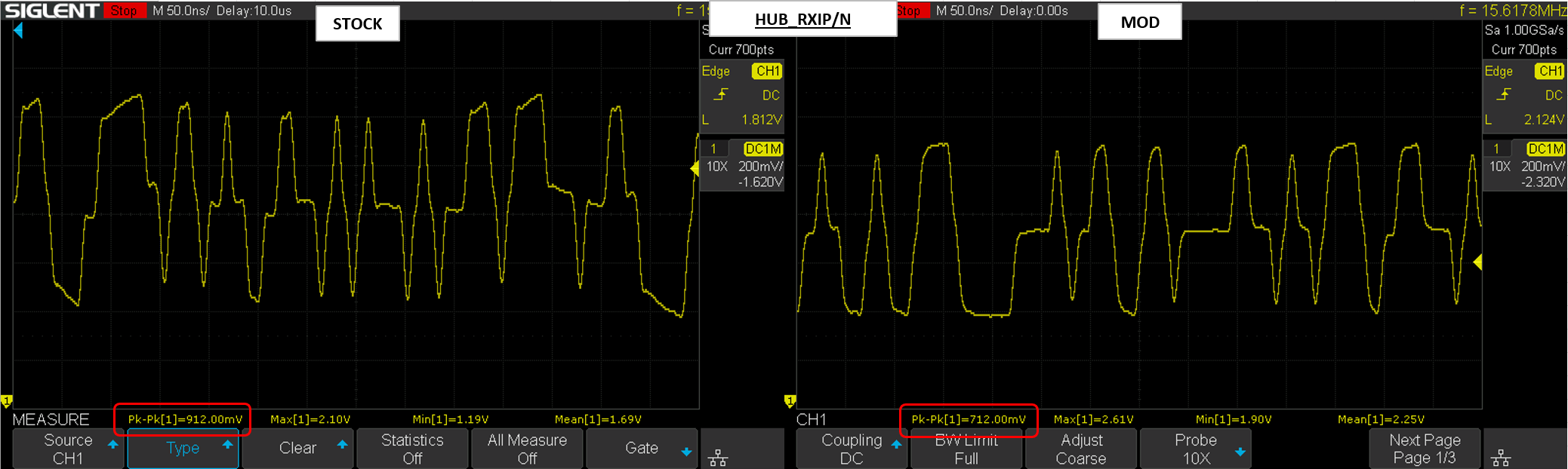
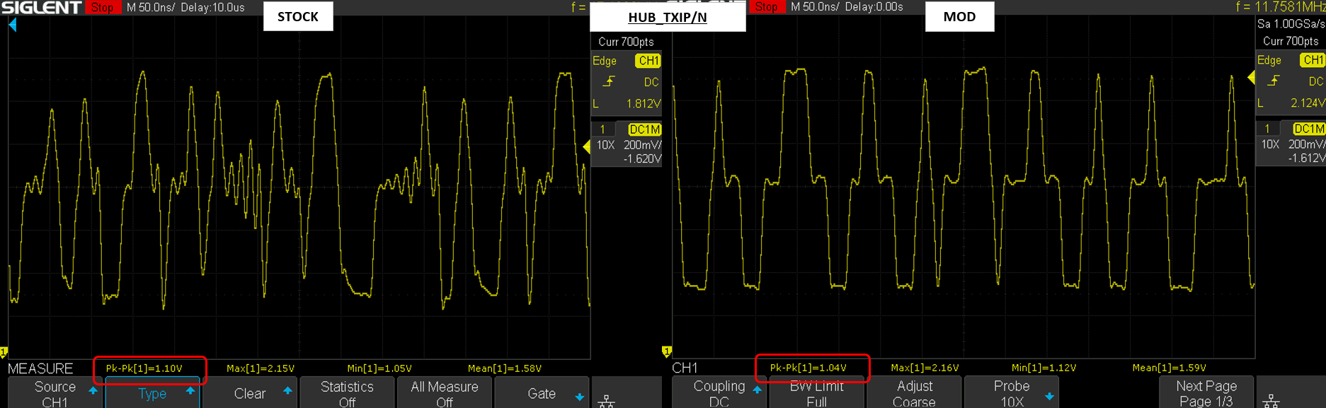
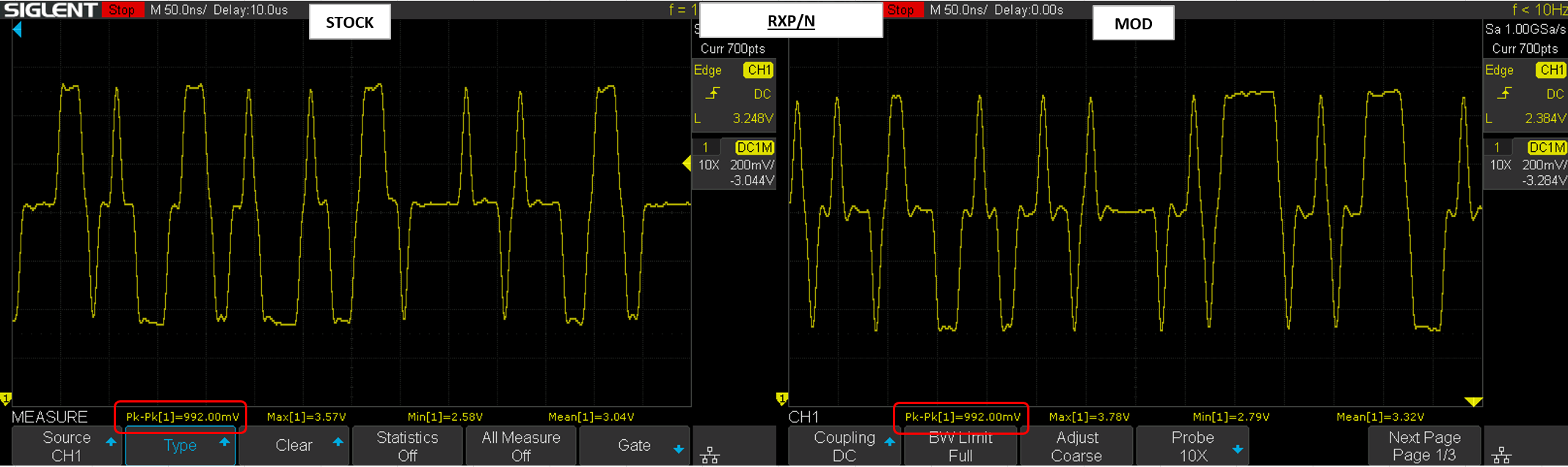
LAB: SI Analysis ------------- ( Pending )

LAB: Power Analysis ------ ( Pending )

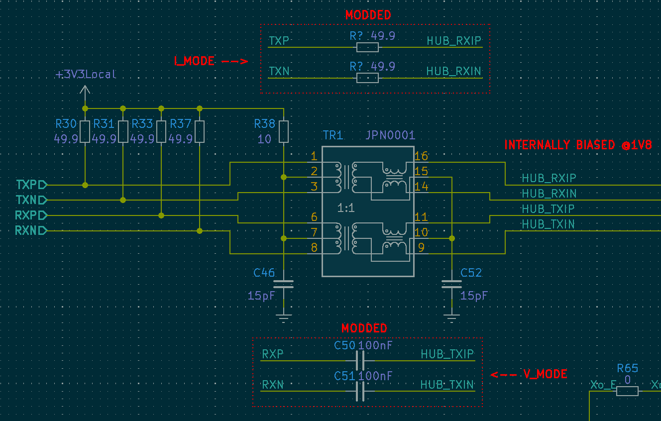
Derisk Capacitive XFRM - ( Pending )

IC-Plus-IP175G.pdf

Ethernet Switch Datasheet

Adobe Portable Document Format - 1.15 MB - 05/16/2024 at 05:21

Preview
Download

  • A Transformerless PHY to PHY Connection – Success (Sort of)

    Jesse Farrell6 days ago 0 comments

    I was able to get the connection between the two PHY’s working, but more tuning is needed. As it stands, these are all just “eye-balled” values, and that really doesn’t sit well with me. What I really need to do is read the 10BASE-T and 100BASE-TX standards to better understand the underlying protocol. Even understanding the protocol, I still don’t know the exact architecture of either PHY. Nevertheless, I’ll post the results I have so far to document the journey.

    I’ve collected some A/B comparisons for the transformer (xfrm) and xfrm-less solutions. The control uses a Pulse H1102NL, and the xfrm-less solution uses either a resistor or capacitor in its place.

    So first let’s look at the change to TXP/TXN shown above. This signal is driven by LAN9514 (Current-Mode), and the MOD was a small series resistor. The main thing I noticed is a shift to the peak-peak value, and the dc-offset of the signal. I’m impressed how well it handled this change in impedance. 

    That was the sending end, now let’s see what’s received by I1P75G (net HUB_RXIP/N above). Its okay, though somewhat overly attenuated. I suspect some tweaking would be beneficial here!

    Next, we’ll look at the data on the sending end of voltage-mode driver (I1P75G). The MOD here was a pair of 100nF coupling caps. 

    I believe the ringing on the STOCK circuit can be explained as follows; When both HUB_TXIP(N) are equal then there won’t be any current flowing into the windings of the xfrm and it appears high impedance to the driver. Moreover, any small amount of current that is conducted through the center-tap and its small capacitor would be impeded by the common mode choke. Both these factors effect the load impedance seen by our voltage-mode line driver. 

    Lastly is the received signal at LAN9514. The signal looks great, but the DC offset is in need of some attention. The received signal is biased to 3V3, as a result the AC coupled signal rides on-top 3V3 and throws it up/down by 500mV. As a result, I’m likely overstressing the LAN9514 receiver.

    Transmission Line – Realization

    After stressing about the termination of the signal for longer than I care to admit, I came to the realization that its not particularly critical here. The rise times are ~3ns, so the frequency is approx. 117MHz (0.35/3). In FR4 that frequency has a wavelength of ~1.208meters. So the critical length would be about 60mm (λ/20), depending on who you ask.

    I’ll keep this in mind for my next round of changes. Atleast the link b/w my two PHY's is stable now!

  • A Transformerless PHY to PHY Connection – Failed Attempt

    Jesse Farrell05/24/2024 at 04:55 0 comments

    The connection between the USB-ETH controller and the ETH switch doesn’t need to be isolated. Its on the same board with the same reference plane. I’ve included the transformer for now as a failsafe, but there’s a network of DNP’d parts on the backside of the PCB that will hopefully replace the transformer in REV01 (cost savings!).

    There are several application notes that outline transformerless PHY-PHY communication, but the exact implementation depends on the line-driver topology, and seems pretty silicon dependent. A good overview of the two line-driver topologies is provided in ENT-AN0106. The main takeaway are the two images shown below. 

    So how can we accomplish this without the transformer? There’s no reference design or app-note for my specific devices, so I’m going to need to do some research to better understand the topic. Based on the termination of the devices I believe LAN9512 uses a current-mode line driver, whereas I1P75G uses a voltage-mode line driver. Linked below are several app-notes I read to help design the interconnect.

    AN2190 - Transformerless Applications of Microchip’s Ethernet Devices (Current-Mode)

    TLK110 - Ethernet PHY Transformerless Operation (Current-Mode)

    RTL8305SC – Single Chip 5Port 10/100MBPS Switch Controller (Current-Mode)

    ANLAN120 – Capacitive Coupling Ethernet Transceivers without Using Transformers (Both Modes)

    ADI WIKI - ADIN1300 and ADIN1200 with Capacitive Coupling (Voltage-Mode)

    SNLA088A - AN1519 DP83848 PHYTER Transformerless Ethernet Operation (Current-Mode)

    Interfacing Intel® 8255x Fast Ethernet Controllers without Magnetics (Current-Mode)

    Maybe I was worried for nothing, the transformerless design looks suspiciously simple... In nearly every document the transformerless application is just a coupling capacitor placed in the signal path b/w the two PHY s. See example below from AN2190 (Current-Mode).

    Shown below is the existing biasing network for the current-mode line driver (LAN9512). Based on everything I’ve read I should just be able to remove the magnetics along with its supporting CT bias, and couple each data lines with a >15nF capacitor.

    On the voltage-mode side. I believe I’m able to directly connect each line to the coupling caps, since (I recently discovered) the device is internally biased. The final network is shown below.

    Oh boy does this not work. Probing the voltage-mode side (I1P75G), it seems like the bus is floating. It periodically droops down to GND, then shoot back to VCC.  I was able to get the link working but I’m still not happy with it… will discuss my solution in the next post.

  • Cheap Chip Woes - Ethernet Switch

    Jesse Farrell05/16/2024 at 05:20 0 comments

    After getting most of the peripherals figured out in the design, I started delving deeper into the datasheets for the core components. I should be doing this earlier in my design, but this is a hobby project dang-it, I think I’m allotted a handful of poor decisions.

    Most of the parts had reasonably clear documentation, except for the cheap ethernet switch I selected early in the design. I’ve added the datasheet to the documents if you want to play along. Among the general lack of reference designs, I found the following…

    • PLLVCC (Pin7) – What do I connect it to!!!
      The datasheet doesn’t specify where this pin should be connected. Is the rail generated internal or do I need to power it externally? Is it especially sensitive, and maybe needs some ferrites, or just a local decoupling capacitor? If you search the entire datasheet for “PLLVCC” you’ll find two instances. One is the pin diagram, the other is the pin description, “Power of PLL circuit”.
      Resolution – For the first prototype I’ll add a jumper to power PLLVCC either from 3V3, 1V0, or leave floating w/ decoupling.
    • VREG_LDO (Pin41) – Min Capacitance?
      I’d really like it if the datasheet gave any sort of comment regarding output capacitance for the internally generated regulator. What is required for stability at least, or even a comment saying there IS no minimum….
      Resolution – Adding 0603 1uF Cout. Larger package allows for tweaks later if needed.

    • EEPROM – What Address?
      This one is pretty depressing, and would have been exceptionally easy to add correct. The device uses an external I2C EEPROM that can store configs that are loaded at startup. However, the address of this EEPROM isn’t specified.
      Resolution – Select EEPROM with configurable address. Sniff bus when prototype board arrives.

    • Magnetics Ect 
      This might be caused by my inexperience in networking related designs, but I’d really like to see some baseic design recommendations for the magnetics. My understanding is that the topology of the PHY can have several downstream affects for the termination / center tap on the transformer. Lacking this info, I’ll design in what seems most widely used.

  • Early Design

    Jesse Farrell05/09/2024 at 05:00 0 comments

    Overview

    I’ve been thinking about making an ethernet switch for awhile and finally found a good reason to make my own. At work I often have to use 4 tools for high level debug;

    • Ethernet Switch
    • USB HUB – Lab Computers long since ran out of USB
    • USB to Ethernet Adapter
    • USB to RS232 Adapter – For debug

    It’s a real pain to have to scavenge all these adapters from around the lab, and the assortment of dongles takes up valuable bench space. The goal of this project is to Frankenstein these 4 devices into a single design.

    FYI for anyone reading. I’m not very familiar with the networking stack, so if I sound a bit uncertain about the topic it’s because I am… (part of the reason I wanted to do a project related to networking. Time to do some learning!)


    General Block Diagram

    I’m using a “keep it simple stupid” philosophy for this design. As such the block diagram looks eerily similar to the 4-tool amalgamation I just mentioned. Something that might be interesting is the PHY-PHY connection b/w the USB to ethernet adapter and the switch. I don’t need any isolation there, so no need for expensive magnetics.

    Now that I have the rough functionality worked out, I need to see what components are actually out there (and at what price!). As much as possible I’d like the design to be (a) cheap and (b) simple. I’ve been in firmware hell for another project, so I’ve had my fill of SW/FW debug for a while.


    Exploration - Ethernet Switch

    There really isn’t much on Digikey. At least not within my budget. Filtering for an in stock / non-marketplace / Ethernet switch, leaves me with several Microchip parts all >$5 at low quantity (see for yourself -> Digikey Search).

    Let’s see what China has to offer. LCSC conveniently has an entire page dedicated to “Ethernet Switches” (here). Filtering on cheapest in stock part lands me on IC Plus IP175G. Can’t say I’ve heard of this manufacturer but at ~$1 it has my attention.

    I’ve read through the datasheet and it seems like it fits the bill for my project. Its got an integrated MAC (thank God), decent buffers (I think?), and some more advanced features. Its recommended application is “5 port 10/100 Dumb swith” and “4TX+1FX Dumb Switcn”. The switch must be extra dumb!

    I did some hunting for reference design, but its very bleak. There’s no official reference design, nor is there any open-source example. The best I could find was this product (SwitchBlox Nano) uses the chip, so clearly its 


    Exploration – USB to Eth / HUB

    Digikey doesn’t seem to have ANY cheap options for a USB to ethernet adapter. In this case it seems like I can’t really avoid an expensive part, and I’m not sure I’d want to anyhow. I’d like a more widely available part with good support, so I don’t have to fight with any windows driver wackiness.

    I ended up going with the Microchip LAN951x series. Its an integrated USB to ethernet adapter coupled with a USB HUB. Its only USB 2.0, but for my use case I don’t need heaps of bandwidth. I haven’t done a deep dive of the datasheet yet, but it looks like I could easily use any of the 3 variants; LAN9512 / LAN9513 / LAN9514. The last digit reflects the number of USB ports present on the HUB. I’ll design in LAN9514 and DNP parts as needed to support the cheaper variants.  

    When searching for reference designs, it looks like this part is even used on the Raspberry Pi 3! That’s handy.


    Exploration – USB to RS232

    Another adapter that will be potential for windows driver wackiness. Similar to the previous adapter, I’d like to avoid the bottom of the barrel options. I suspect I’m overthinking the driver setup headaches, but I’ve never worked on a board that needs any kind of windows support so…. Rule number 1 “keep it simple stupid”.

    My first thought for RS232 support was FTDI, I think most designers have used or at least heard of this manufacturer, and I figured it would be dead...

    Read more »

View all 4 project logs

Enjoy this project?

Share

Discussions

Similar Projects

Does this project spark your interest?

Become a member to follow this project and never miss any updates