 Johan Winer
Start with making a model of the finished wooden casing, try out different distances of the tubes to make a good looking clock.
My original case model was much smaller and the finished clock would not have fitted inside, so go with some margins.
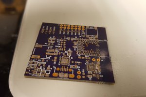
Create a drill mask for the tubes' legs. I took a photo of one tube, from below and printed 4 copies of it on paper with the distance between the tubes that I had decided on. Paste the drill mask on the pcb and drill the holes for all the tubes' legs.
Drill holes for the ic:s, I made many sketches before I managed to place the ic:s so that I would be able to connect each ic pin with a tube's legs.
Drill holes for the ic:s and extra holed beside the ic's pins that should be connected to GND, PWR and A-D to simplify the soldering of cables to the boards.
Use the permanent marker to draw lines from the ic:s to the tubes' legs (does not have to be very thick, maybe 1 mm).
Also draw lines between the holes connecting the pins and legs of the tubes and the ic:s to the holes for the cables that later will be soldered to the boards to connect the board to the arduino and power supply.
Etch the board (pcb). (I only had small boards so I had to use two separate)
Solder the resistors, cables, ic:s and tubes to the pcb.
Getting the tubes' legs into the drilled holes in the pcb can be tricky, 13 different small legs that should all be fitted into place at the same time. I suggest cutting the legs into slightly different lengths, in that way you can fit one leg at a time while moving the tube closer and closer to the pcb.
Getting all the tubes to face the exact same direction is hard. I drilled many test holes in a separate board and fitted the tubes into place and adjusted the drill mask (printed paper copy of the tubes' legs position) untill the tubes were lined up.
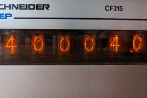
Assemple a step up circuit, that can deliver 180V, and approxemately 7mA to each tube. 5 watt is more than enought for 4 IN-14 tubes and one bulp.
The resistors I uesd in the circuit board was 1/4 watt, therefore I had to use two resistors instead of one between the power and each IN-14 tube. The power was thus split over two resistors and the watt over each resistor lowered beneath 1/4 watt.
See
P = I * U
1/R_total = 1/ R_1 + 1/R_2
U = I * R
To power the device I use an simple wall jack transistor from 230V AC to 9V DC 500mA.
See schematiks for details.
At the back of the wooden case I mounted a button by which I can speed the clock forwards. After releasing the button, a register is switched to that the next time the button is pushed, it will speed the clock backwards. Making it possible to go backwards if I held the button for too long and went past the desired time.
 Bhavesh Kakwani
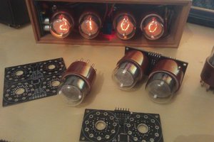
 Thomas Flayols
 Walter