 trax
traxFull schematics and firmware for microcontroller can be found on project page here:
http://www.elektronika.ba/843/inductive-loop-vehicle-detector-v2-1/
PCBs: http://www.elecrow.com/inductive-loop-vehicle-detector-v21-p-1458.html
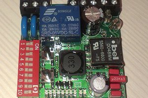
Inductive Loop Detector works by detecting an inductance change in wire loop (coil) that is buried in pavement.
Already have an account? Log in.
To make the experience fit your profile, pick a username and tell us what interests you.
Full schematics and firmware for microcontroller can be found on project page here:
http://www.elektronika.ba/843/inductive-loop-vehicle-detector-v2-1/
PCBs: http://www.elecrow.com/inductive-loop-vehicle-detector-v21-p-1458.html
I am happy to announce that professionally made PCBs for project Inductive Vehicle Detector are available for sale at Elecrow website.http://www.elecrow.com/inductive-loop-vehicle-detector-v21-p-1458.html


Hi Dimitar, thanks for the kind words. The project is completed (at least this iteration) and it is tested and currently actually in use in few road barriers in my city :-)
This device can not measure vehicle speed standalone, but with two of these devices you can safely measure the speed by using third microcontroller that will read outputs of these two detectors. By knowing the distance between loops in ground and by measureing the time difference between signals provided by these two detectors, you can measure the speed as: v=s/t. (s=distance between loops, t=measured time between signals).
I am currently contemplating a dual channel version of this device (but it will not be able to measure speed because I will be multiplexing loops on this same microcontroller) so high speeds will not be measurable. I don't know what hardware professionals use for their speed detectors - would love to see it :-)
edit: I just read your edited comment. Maybe you could give me some pointers about generating my own frequency by MCU instead of free-running oscillator I am currently using?
To be honest the free-running oscillator as you said it (probably better than what I said before HW/IC/аnalog oscillator) is more proven for some applications. Still the Digital based oscillator can give you capabilities, repeatability of the design , etc. It's all basic PROS and CONS to find the balance. To be hones on PIC16/18 there are ways to do quality FREQ generation, yet it steps would not be very precise. If at all in your design you shift/change the FREQ to do detection. As I said - It was obvious to me that you can not measure speed, even at mid-high velocity of the vehicle, what's left for high speeds. Also the design (idea, correct me if wrong) for 1 more MCU to use 2 modules for that detection will introduce new problems. But I do like distributed systems for their low chance of failure due to distributed capabilities/features of the system. + That's the recurring trend nowadays ;-)
What I do in my Industrial-metal detector model (http://tomov.eu/mdv1/) is using DAC of MCU to generate a Frequency (40kHz to be exact, but with the 1MSPS Dac I got very good 70+kHz freq, very precise). Then 1st feed that DAC-output signal to a buffer op-amp in unity-gain configuration ( http://www.facstaff.bucknell.edu/mastascu/elessonshtml/OpAmps/OpAmp3Note1Buffer.html ) or also called voltage-follower ( https://en.wikipedia.org/wiki/Operational_amplifier_applications#Voltage_follower_.28unity_buffer_amplifier.29 ) , thus allowing me to feed the signal to powerful op-amp to generate higher voltage, higher power amplified signal of the original one.
Long-story short .... U use a DAC or other MCU peripheral to create the low-voltage, low-power signal, then one op-amp to buffer+isolate the signal from the MCU and afterwards feed to second more powerful op-amp to actually 'boost the signal' in Power ( i.e both Voltage and Current). Some RC filters are needed of course for anti-aliasing and to guaranty the specter + no distortions in the signal from that design. It's better if you integrate them into the Op-amp scheme of implementation. In my case i did it the old fashion way, cause actual metal detecting is not a straightforward task with all that analog stuff going on. Surely U have experience that more or less too. to be honest I distributed the task so I can modify both with more ease and precisely detect problems, yet that presented new challenges. So it's all in the balance , again and again :D
AFAIK PIC16/18 don't have a dedicated DAC, but I remember well they had some sort of Trigger, Charge, Compare , etc peripherals integrated. I used it once for Capacity detection to get Capacitive buttons way before they started putting actual peripheral for that. I even used PWM to lower the cost and not get PIC with those Charge, Compare, etc.
In my design of Industrial Metal Detector Model You can see what I'm doing is even one step further in generating digitally the signal - Using IIR filter as digital oscillator. Yet there's a basic + proven approach to have DATA of the Steps of the sinusoidal signal and feed them to the proper peripheral - PWM , DAC, R2R matrix even, which is very efficient, yet costly and hardly reproducible. Or like I said on PIC16,18 - Charge, Capture Time period, discharge - it's an interesting approach to be honest, but for me it's too much of poor MCU arch and peripheral (especially this one).
In summarization - I would advise you to continue your design efforts forward and in parallel (it's not a joke - multitasking ;) ) investigate how a Digitally Generated FREQ can assist, improve or even simplified your design. Because neither of those 3 is ever guarantied !
I also believe that your PCB skills will serve you very well if you decide to go for Digital Generated FREQ design. Again please take a look at PIC24 , which is very different from PIC16/18 , but will give you some room to breathe if you are to evaluate on similar ARCH. To be honest you either go to Cortex-M0/1/3 or go higher in the chain of PIC available Microcontrollers. Other possibility is the one MCU I simply love , yet got 'dumped' for distant future by ATMEL - ATXMEGA.
With PIC16/18 you did 100% right to set outside the signal generation - This way you isolated the task + simplified the firmware and so on. All good things.
To finalize - The project is promising , because of it's foundation as HW and somewhat proven Firmware (you said it's already used commercially , if I'm not wrong). Bare in mind that more and more engineering work for commercial project differs from engineering work for RnD project. Therefore I can not guaranty adding Digital Generated Oscillator frequency will improve your design , but for #Hackaday2015Prize sure will make it stand-out ;) You are the Guy/Engineer here, you have to make the call :-)
GL
Dimitar
Thanks so much for all this info. I was on a vacation and then got busy with work and couldn't find time to reply here. Anyway, thanks again and if I make any progress I will post here :-)
Sure, man. I know that feeling :D I've been job relocating in June and literally could not take my time allocated for anything else than work and relocation tasks. So no worries :-) And to be honest I can be more technically specific ,not so broad on some points in my answer, but still I'm not sure which path you will take so will trow an eye out for your updates. Eventually we might get in thouch again ;-) GL = )
Dimitar
Dimitar, are you still alive? :-)
I am slowly going back to this project, and attempting to make a dual-channel version with some processing (vehicle classification). I still didn't give much though about your idea of generating signal instead of using free-running oscillator. I might take that into consideration as well for this new version.

[this comment has been deleted]
Ok Atmel, here I am. Lets talk by e-mail maybe, or private messages here?
[this comment has been deleted]
Hi Atmel, thanks for the offer. Tempted to move from Microchip to Atmel! What boards do you have in mind? Thanks!
By the way , what happened here. I see deleted comments and ATMEL mentioned ? if you can get ATXMEGA it's a great MCU for your design , especially if u are to add some digital +/- analog feature more ;)
They offered me "some boards" if I switch from Microchip to Atmel on this project :-) They deleted that offer some times after... Don't know what happened. They probably thought that their offer/comment was not public :-)
 Anil Pattni
 Carlos Kuri
I like the idea, I can not say much about the design as it's almost not seen ;) Yet I can determine that You are industrial/embedded guy (experienced) , including I see a lot of commercial-wise design PCB or not just hobby one. But on topic - I like the project, therefore give it a skull, still I'm in a doubt about IF your solution can measure speeding vehicles as it's states, cause the MCU you are using is not very high-perf. , which means not very high freq output, not very high sampling (i.e not low sample time). With just a few words - It's has an idea, the design to me (from what's seen) looks very found , yet I'm not sure the implementation can do what it's meant to do. Regardless I recognize your effort and amazing effort you've put - KUDOS ! :-)
And I wish you luck going forward with your project. I'm not sure I'm going to follow to see the design files , HW, SW , etc. But it's up to you to move forward by accel. the design + making it Open ;-)
Good Luck = )
UPDATE: Well yeah I saw the explanation about the Timers and as expected your FREQ is low, sampling time is high too, but you got results , which is why I'll state again it's promising. Moreover I believe you have 2 options - go for PIC24, dsPIC33 to be in a known ARCH/field. OR switch to some Cortex-M1/M3, cause M0 with fast Operating FREQ and fast enough peripheral. Also you have the ATXMega option which is amazing MCU Architecture, sadly not very used.
Moreover I expected to see HW(IC) based oscilator and again it was there, but if you move to a diff. MCU with more capabilities You can even adapt your Oscillator FREQ and so on. Generated from the MCU is what I mean + gives you capabilities / flexibility. It's not something very hard , cause you have to feed the signal to at least 2 Op-amps OR 1 precisely selected. You can't feed an Op-amp directly from the MCU pin as the current draw will be too much and distort your signal ;) i.e freq. If you do only switching it will be OK, still that implies some more HW/IC analog parts involved.
Last, but not least I assume that's hand-mand/custom COIL . Go for Wireless charging coil ;-) Their range is 110-190kHz and I believe you can work with that frequency looking your description. Moreover you can always optimize code (the firmware) to achieve good sampling times on that freq (if there's a problem, because I don't believe there would be as it's in your device description). So wireless charing coils are good for more than one thing - for more than what they are build ;) #Hackthhem :D
Again Good Luck ! I like your efforts, I like the outcome and what I like even more that this can serve as a good foundation moving forward to a next(gen) Design :-)