-
Temperature node initial setup - firmware/config side
03/10/2019 at 15:43 • 0 commentsAfter assembling the hardware, it's time to get the firmware and configuration in place.
Initial install of sketch is via USB upload from Arduino IDE:
- Plug the USB cable in, look on Arduino IDE for which port has been assigned (under Tools -> Port) and select that port
- Open serial monitor window
- Upload in Arduino IDE
- Hold down "Flash" button and tap "Reset" - keep "Flash" button held down until blue LED flashes and progress display in Arduino IDE shows the upload is in progress - can release "Flash" button then during upload.
- After upload finishes, node will reboot itself. Do "tail -f /var/log/nginx/error.log". When the firmware checks for new sketch and spiffs, it will generate an error as the MAC address hasn't been associated with anything in the server side scripts. The error includes the MAC address - copy that to clipboard
- emacs /var/www/html/tempnode/sketch.php and add new entry in the initialization of the $db array for this MAC address pointing it to a specific sketch (for now I've got one sketch for temp nodes and one for the thermostat)
- emacs /var/www/html/tempnode/spiffs.php and add new entry in the initialization of the $db array for this MAC address pointing it to a specific configuration spiffs file. This file doesn't exist yet, next steps will define it.
- emacs /var/www/html/tempnode/spiffs/Makefile and a new macro for the base directory for this new node, add a new file section, add it to the all and version dependencies
- Copy ~/esp/home-env/tempnodes/data/office to ~/esp/home-env/tempnodes/data/newnode
- Within ~/esp/home-env/tempnodes/data/newnode edit the version.dat, node.txt, mquser.txt, mqpass.txt, mqhumtop.txt, mqpsitop.txt, mqtmptop.txt
- Now that the source directory for spiffs is configured, go to /var/www/html/tempnode/spiffs/ and do make
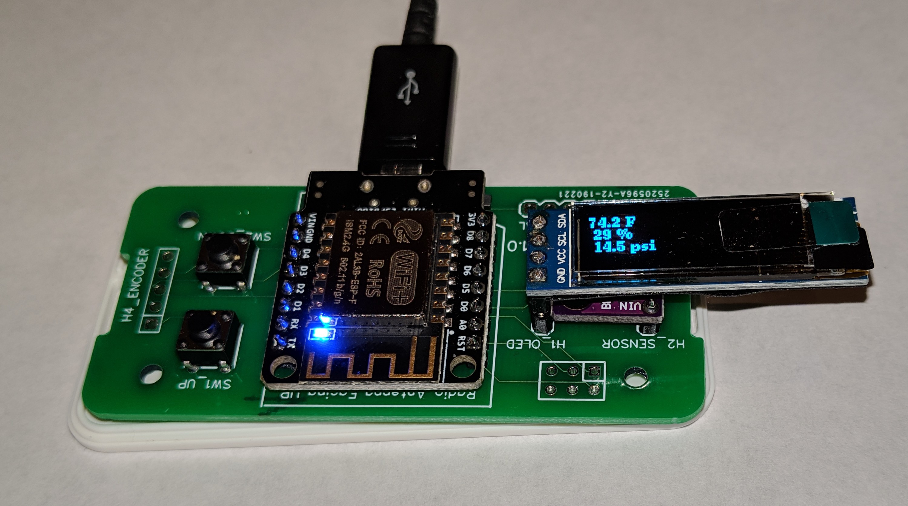
- Reboot new node to get it to load spiffs (the sketch will be the same version that was already uploaded) and confirm on OLED that the node name is picked up from spiffs configuration
-
Temperature node assembly steps
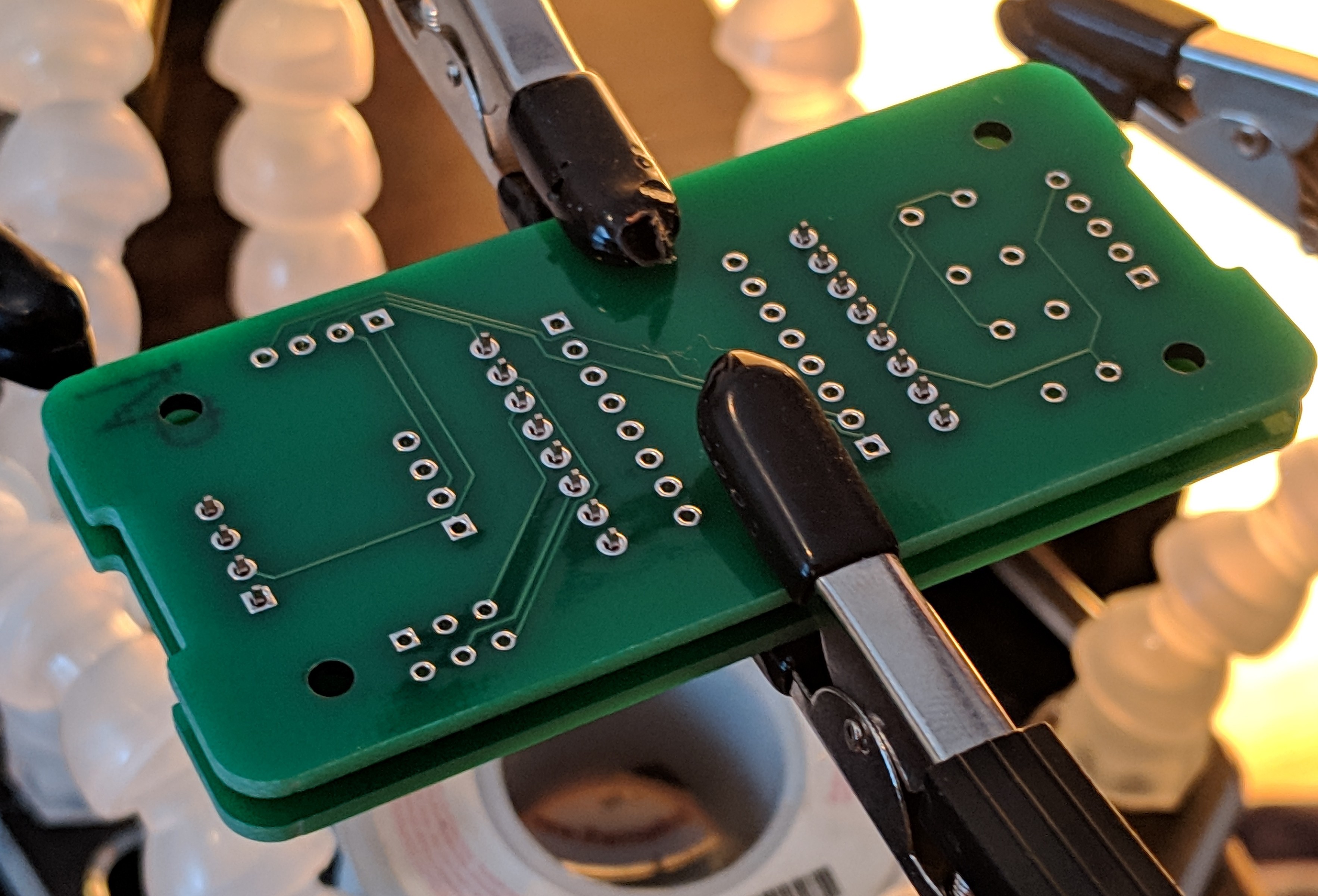
03/10/2019 at 13:46 • 0 commentsFirst I take a blank PCB and put 1x4 header in the BME position and two 1x8 headers in the outer ESP8266 mounting positions
![]()
Next I place another blank PCB over to make a sandwich, keeping the loose headers in alignment, then flip the combination over to solder the bottom side.
![]()
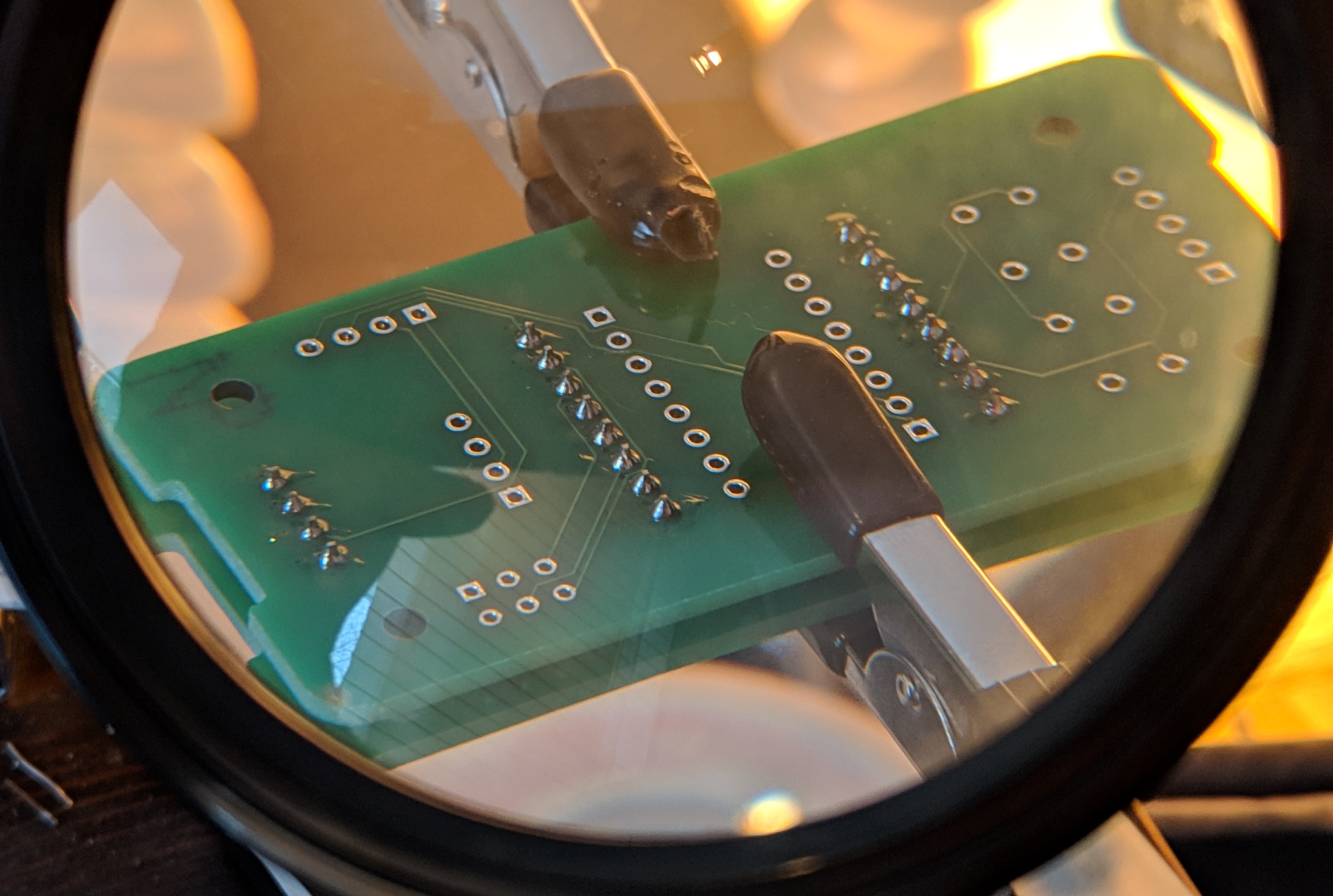
Inspection after soldering
![]()
Then the top blank PCB is removed and I put the ESP8266 module in place and solder it down and trim the header leads with flush cutters
![]()
Next the BME280 breakout is soldered down
![]()
A round milled 1x4 header is soldered in place as a mounting point for the OLED module but this is left as a mating pair not soldered in place.
Two 6x6x6 momentary buttons are soldered down and the completed PCB assembly is screwed down to the Hammond 1551V2WH base plate
![]()
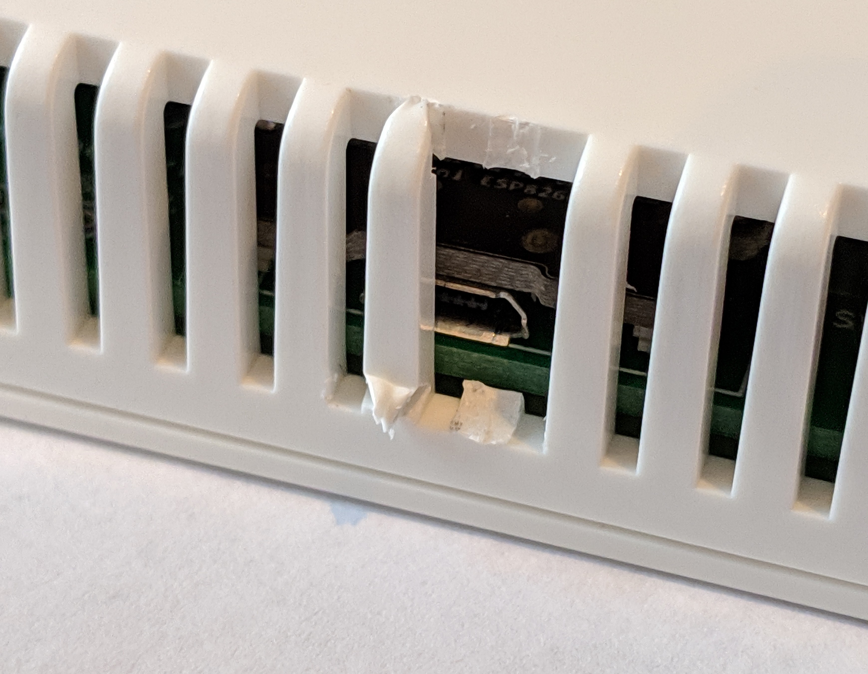
I put the cover on and use flush cutters to cut out two pieces so there is an opening for the micro USB cable end
![]()
-
ESP8266 OTA updates working TLS
03/06/2019 at 12:00 • 0 commentsAll I have to say is that it's amazing how much better things work when you actually follow the provided working examples instead of just loosely following them.
Even got the local timezone being set right.
-
Temperature node cost
03/04/2019 at 02:52 • 0 commentsI think the temperature node hardware is close to finalized so I'm curious to look at the cost to me ($25.39 ea - without tooling) and was curious to see the cost of the equivalent from another source - I found the ecobee room sensors are $75 for a two pack at Amazon (https://www.amazon.com/ecobee-Room-Sensor-Pack-Stands/dp/B00NXRYOIQ)
Item URL Price Enclosure Hammond 1551V2WH 1551V2 at Arrow $1.86 Custom PCB from JLCPCB $0.44 Temp sensor - BME280 from Amazon https://www.amazon.com/gp/product/B0118XCKTG $9.49 ESP8266 https://www.amazon.com/gp/product/B01MU4XDNX $8.50 2 pcs 6x6 microswitch https://www.amazon.com/gp/product/B071KX71SV $0.1 USB wall wart Not sure where I got it $5 Total permanently installed (not including tooling, prototypes, etc) $25.39 OLED module as needed (not permanently installed) https://www.amazon.com/gp/product/B0761LV1SD $5.49 -
ESP8266 OTA updates update
03/03/2019 at 23:17 • 0 commentsI've had a lot of difficulty getting OTA updates to work over HTTPS, so I'm falling back to HTTP for now. I've got it updating the sketch efficiently (meaning, using stock code to check md5sum of file and not bothering to update if the md5sum is the same) using the example code - however I'm not yet getting the spiffs to use the same logic - it's loading every time the ESP8266 boots.
-
Workaround for ordered boards
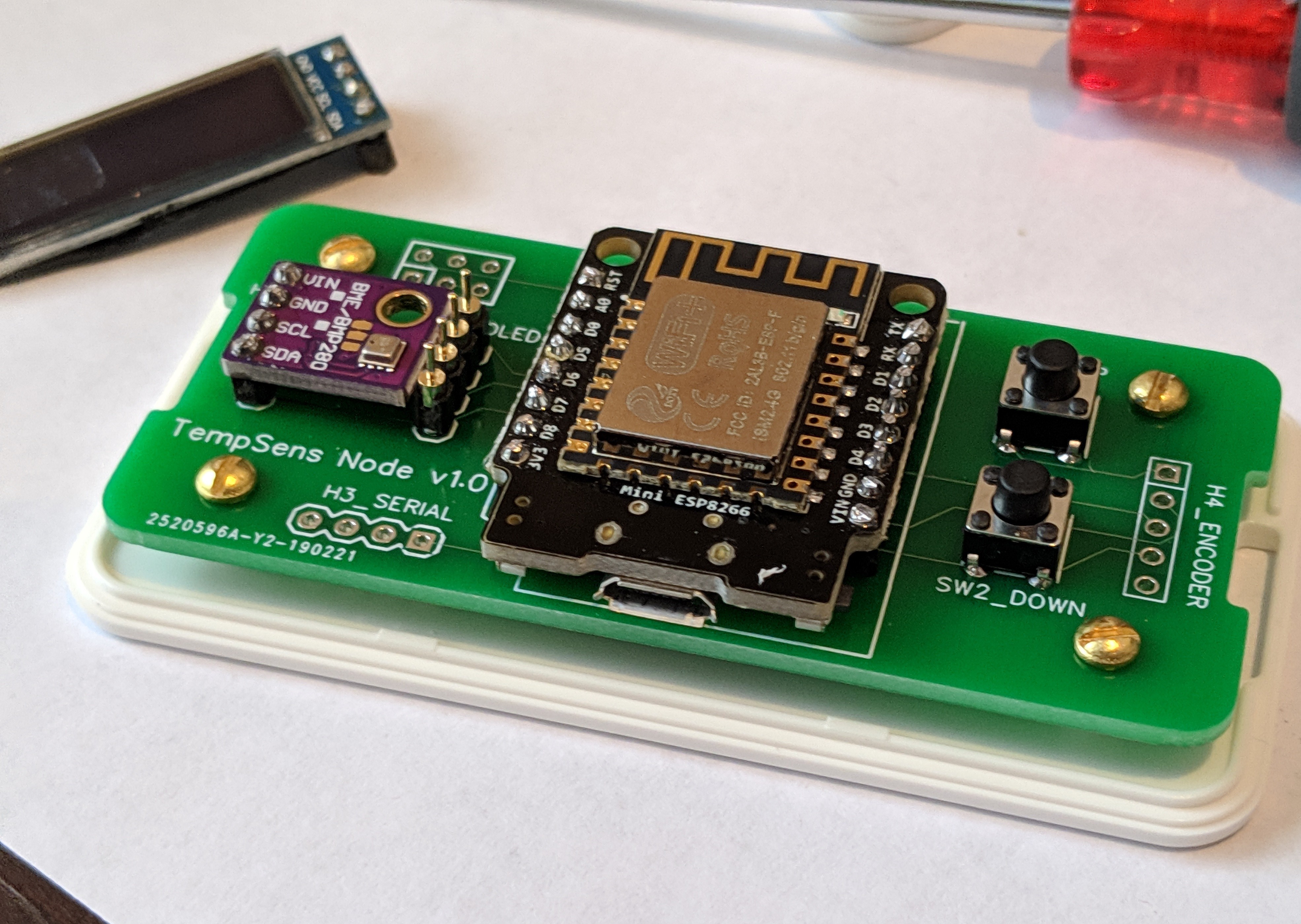
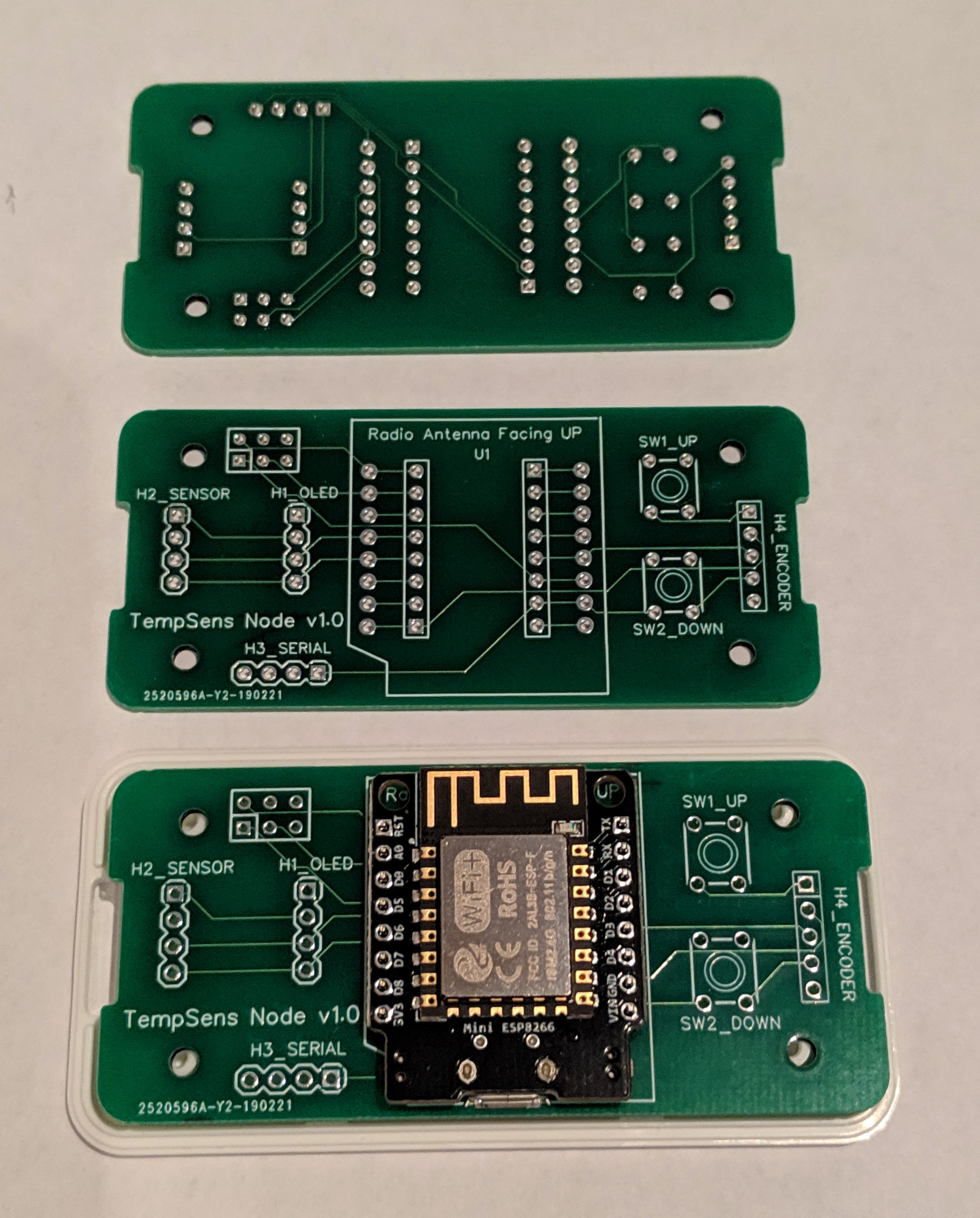
03/02/2019 at 22:56 • 0 commentsIt's a bit of a kludge, but here is a board (top in this pic) assembled to work around the mistake with orientation of the header for OLED - reverse the stack up and flip the board (thanks David for pointing out the way to do this). I think most of the time I'll operate without the OLED plugged in so this won't really matter much.
![]()
-
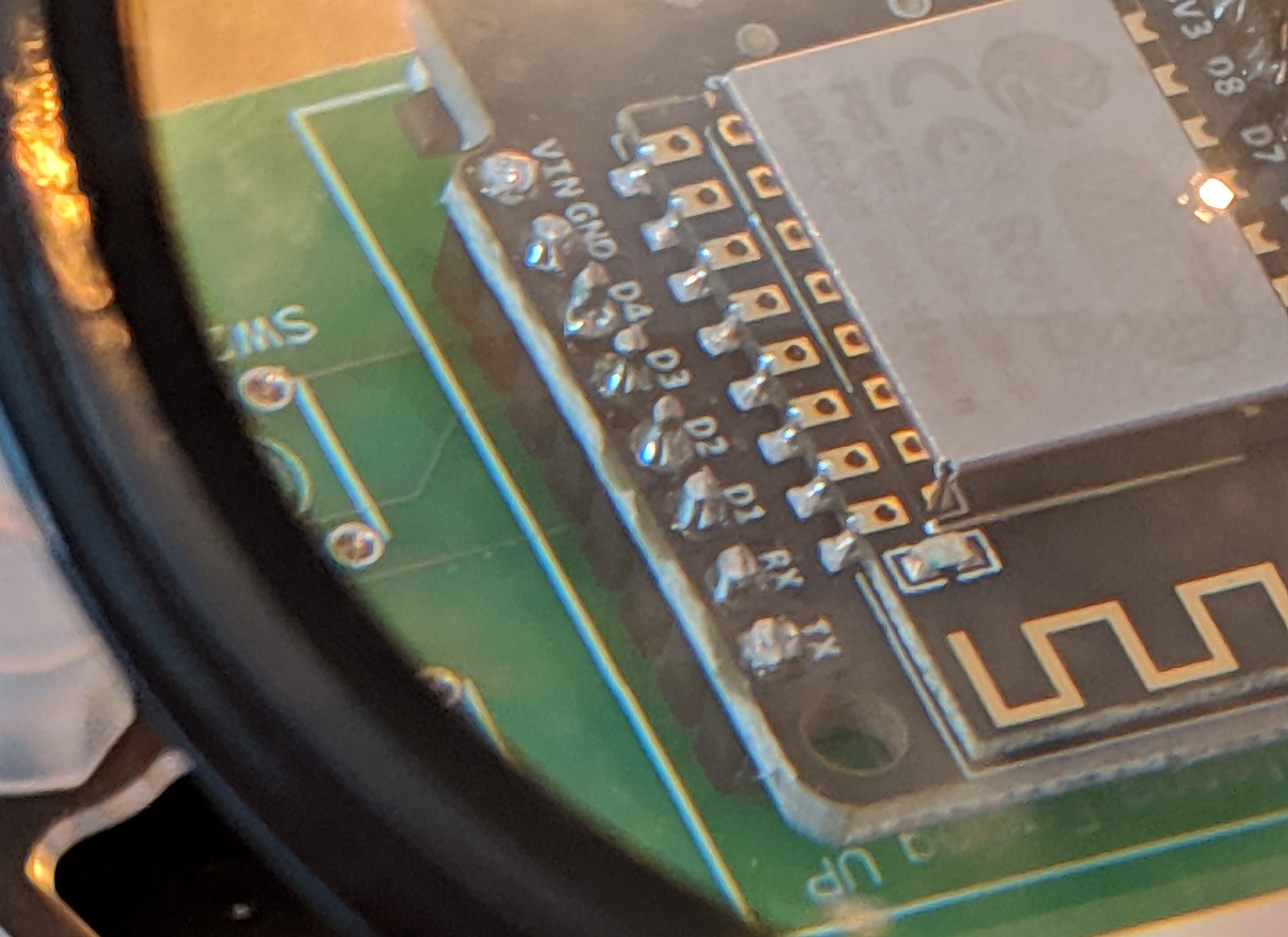
First mistake found on the ordered circuit board
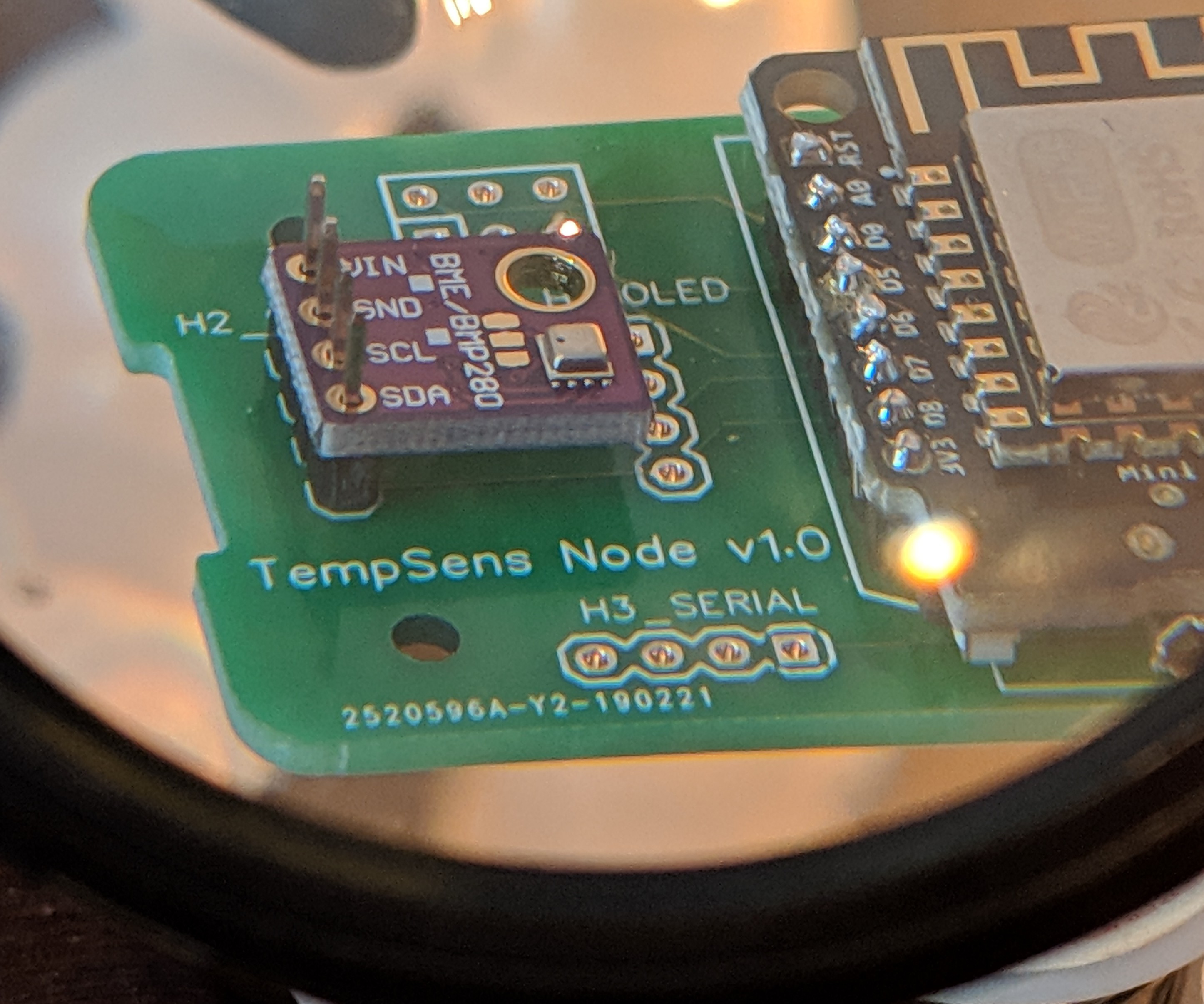
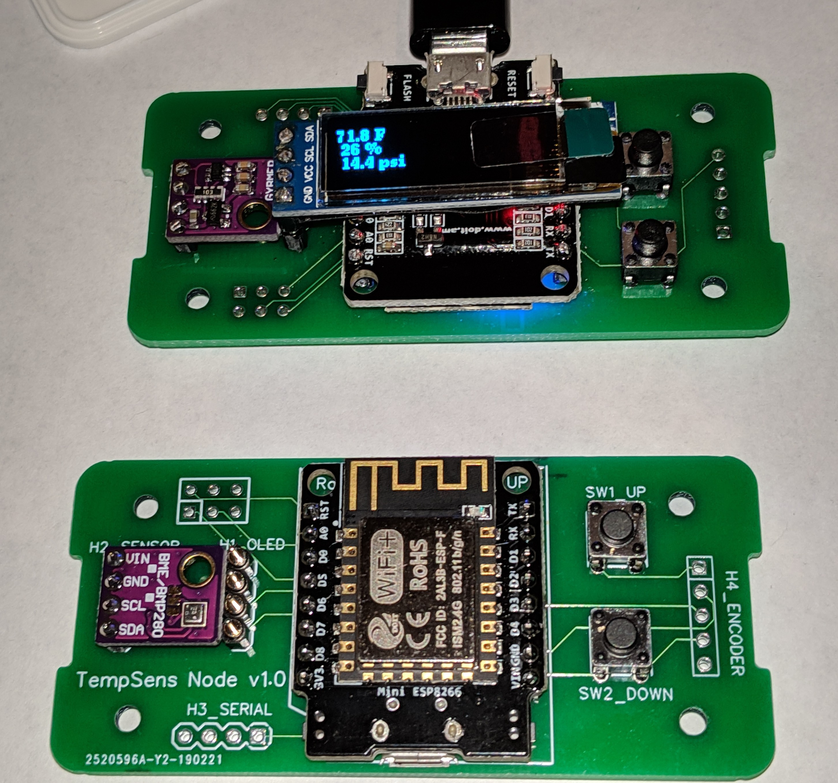
03/01/2019 at 02:04 • 2 commentsThis won't stop me from using these circuit boards either without OLED or in other projects outside of the 1551V2 enclosure; but I found a stupid mistake while soldering the first one up. I got the orientation of the OLED i2c header rotated by 180 degrees. The i2c header for the BME280 breakout board is wrong too but that turns out to be a good mistake as I didn't allow enough vertical room for it to be mounted with a 90° header like I planned, so mounting it the "wrong orientation" works fine. The OLED however is upside down and would stick out of the enclosure. Oops. The good news is that I can just leave it off normally and take the cover off and plug it in when needed.
Soldered up board with OLED installed
![]()
-
Circuit Boards are in
03/01/2019 at 00:26 • 0 commentsOrder arrived, rough mechanical fit looks good so far. It also fits in the 1551V size 2 enclosure nicely.
![]()
-
Circuit Boards are in
02/28/2019 at 23:23 • 0 commentsOrder arrived, rough mechanical fit looks good so far. It also fits in the 1551V size 2 enclosure nicely.
![]()
-
Sensor Node PCB ordered
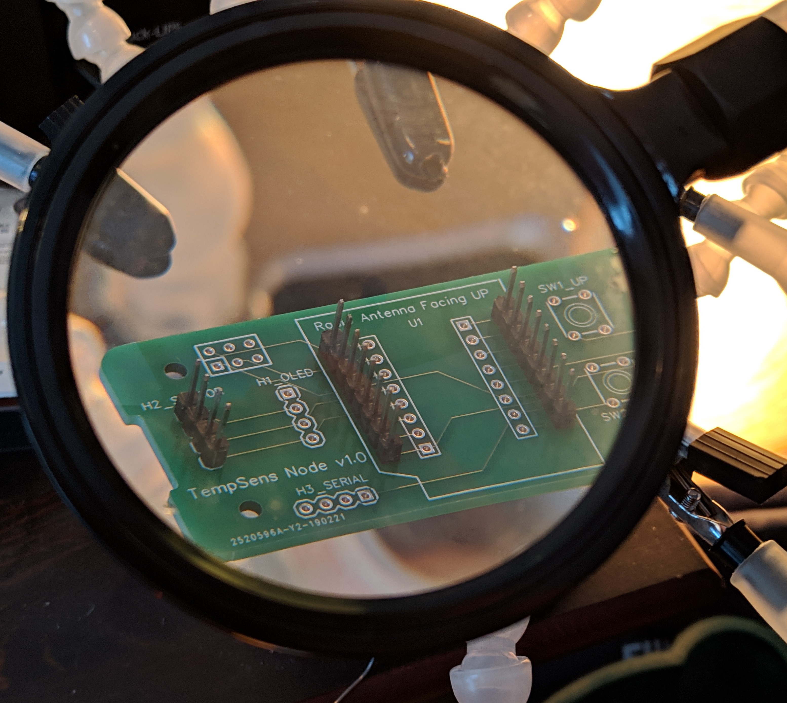
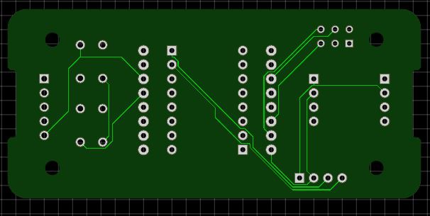
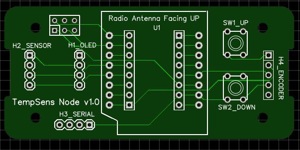
02/21/2019 at 12:50 • 0 commentsI used EasyEDA to design and order through JLCPCB a PCB for the sensor nodes to fit into the Hammond 1551V size 2 enclosure. I could have done the minimum order of 5 boards for $2 (and probably will go that route when it comes time to order a board for Dwalin), but since I can easily see using 5 of these, I wanted to have plenty - so I ordered 30 for a total cost of $13.05 shipped w/ DHL.
![]()
![]()
I set it up for I2C to two different headers, one with the pinout for the OLED modules I have and one with the pinout for the BME280 breakout board module I have - between them they don't have the same pinout for Vcc and GND. I set up for either two pushbuttons or for an encoder. I set up a serial port (GND, Vcc, TX, RX). I also set up a second set of headers inboard of the headers for the ESP8266 module (it's roughly Wemos D1 mini sized, but slightly smaller), and finally a 2x3 header to bring out a second set of pads for the pins I'm not making any use of.
Since this board has at least two pads for every pin, I think I'll be able to use this for prototyping other projects in the future.
Home environment monitor
Yet another wireless network of environmental sensors in a home