Lutetium
-
Hack Chat Transcript, Part 3
07/17/2019 at 20:05 • 0 comments![]() I'm sure you have some you could share as well
I'm sure you have some you could share as well![]() how much calibration sucks really depends on your production volume and how willing you are to invest the time & money to make it not suck
how much calibration sucks really depends on your production volume and how willing you are to invest the time & money to make it not suck![]() > I'm working on a DIY CO detector using a sensor like this:
> I'm working on a DIY CO detector using a sensor like this:That's a great idea @Alex Ryker! What does the circuit look like?
![]() like are you pulling off a manufactured sensor...or are you creating the sensing element from scratch?
like are you pulling off a manufactured sensor...or are you creating the sensing element from scratch?![]() > I'm working on a "precision rectifier" circuit also known as a "super diode". A diode and op amp (to be sampled by an ADC).
> I'm working on a "precision rectifier" circuit also known as a "super diode". A diode and op amp (to be sampled by an ADC).Another good looking project @Will Patton. Any circuit you can share here?
![]() > how much calibration sucks really depends on your production volume and how willing you are to invest the time & money to make it not suck
> how much calibration sucks really depends on your production volume and how willing you are to invest the time & money to make it not suckAs the Teensy creator would surely know :-D Lots of volume there!
![]() How much calibration is there for your designs @Paul Stoffregen ?
How much calibration is there for your designs @Paul Stoffregen ?![]() fwiw, I'm working right now with a relatively new "smart amplifier" chip, which requires a calibration of the speaker
fwiw, I'm working right now with a relatively new "smart amplifier" chip, which requires a calibration of the speaker![]() ahh, yeah
ahh, yeah![]() so you're characterizing and then storing the variables in an EEPROM or something?
so you're characterizing and then storing the variables in an EEPROM or something?![]() I'm trying to do as much from scratch as possible--more fun that way :)
I'm trying to do as much from scratch as possible--more fun that way :)I don't have much drawn out yet, but I've cleared my schedule this Saturday to change that. I'll probably make a Hackaday.io project out of it once it's a little more substantial.
![]() >I'm sure you have some you could share as well
>I'm sure you have some you could share as wellHonestly, I haven't worked with much in the way of analog for a while; I've mostly been in battery and power systems, and more generalized high volume. I'm definitely always curious about everyone else's tricks. =)
![]() a lot of the gas sensors have some kind of chemical element and then the output needs to be amplified somehow. So that's a good project, but there can be a lot of variability
a lot of the gas sensors have some kind of chemical element and then the output needs to be amplified somehow. So that's a good project, but there can be a lot of variability![]() i've got some photodiodes with bandpass filters on, that i'm trying to find the best way to measure the light at a certain wavelength, i presume i'd need to use an op-amp like in your diagram, to convert the current to voltage? but it seems there's different modes to use a photodiode, which confuses me somewhat (the photodiodes monitor two different wavelengths, trying to measure a peak/trough of a liquid for a type of spectroscopy)
i've got some photodiodes with bandpass filters on, that i'm trying to find the best way to measure the light at a certain wavelength, i presume i'd need to use an op-amp like in your diagram, to convert the current to voltage? but it seems there's different modes to use a photodiode, which confuses me somewhat (the photodiodes monitor two different wavelengths, trying to measure a peak/trough of a liquid for a type of spectroscopy)![]() > i've got some photodiodes with bandpass filters on
> i've got some photodiodes with bandpass filters onPassband of light or of the electrical signal?
![]() For Teensy, there's really no calibration at all during testing. The chip's ADC does have a self calibration that's done at startup, which appears to just null out DC offsets
For Teensy, there's really no calibration at all during testing. The chip's ADC does have a self calibration that's done at startup, which appears to just null out DC offsets![]() passband of light sorry
passband of light sorry![]() Good to know! What I've been thinking about most recently is powering the thing--ideally I'd like it to look like a lot of COTS CO detectors and have an integrated AC plug. However, I'm not quite sure how best to go about that--safety and potential noise are concerns I've had. Any thoughts on that?
Good to know! What I've been thinking about most recently is powering the thing--ideally I'd like it to look like a lot of COTS CO detectors and have an integrated AC plug. However, I'm not quite sure how best to go about that--safety and potential noise are concerns I've had. Any thoughts on that?![]() > i'm trying to find the best way to measure the light at a certain wavelength, i presume i'd need to use an op-amp like in your diagram, to convert the current to voltage?
> i'm trying to find the best way to measure the light at a certain wavelength, i presume i'd need to use an op-amp like in your diagram, to convert the current to voltage?Yeah, you'd want to convert it. It's tough because photodiodes effectively combine all of the wavelengths they absorb
![]() > However, I'm not quite sure how best to go about that--safety and potential noise are concerns I've had. Any thoughts on that?
> However, I'm not quite sure how best to go about that--safety and potential noise are concerns I've had. Any thoughts on that?Out of my pay grade (outside the scope of this chat, but a good subject)
![]() For a couple products I made on a consulting basis (back in the days when Teensy was just getting started....) I used quite a lot of calibration. I even still have an Agilent 34410A on the workbench - which was used for a of that old work
For a couple products I made on a consulting basis (back in the days when Teensy was just getting started....) I used quite a lot of calibration. I even still have an Agilent 34410A on the workbench - which was used for a of that old work![]() > The chip's ADC does have a self calibration that's done at startup, which appears to just null out DC offsets
> The chip's ADC does have a self calibration that's done at startup, which appears to just null out DC offsetsThe best way to do it
![]() I think a lot of sensors are piping out digital signals these days
I think a lot of sensors are piping out digital signals these days![]() so it's getting less common to have to deal with analog signals for some things
so it's getting less common to have to deal with analog signals for some things![]() there are a bunch of off the shelf chips that are "analog front ends" that take care of a lot of things
there are a bunch of off the shelf chips that are "analog front ends" that take care of a lot of things![]() One of those old products had an AVR chip, with signals coupled to its ADCs, and a 2% (but highly stable) reference chip.
One of those old products had an AVR chip, with signals coupled to its ADCs, and a 2% (but highly stable) reference chip.![]() the signals went through resistor dividers which used resistors in those little 4-resistor arrays (1206 size SMT), so the resistors needing ratios were on the same physical package to track with temperature, but the tolerance wasn't good at all
the signals went through resistor dividers which used resistors in those little 4-resistor arrays (1206 size SMT), so the resistors needing ratios were on the same physical package to track with temperature, but the tolerance wasn't good at all![]() yeah, those kinds of problems can be stinkers
yeah, those kinds of problems can be stinkers![]() that's trading the time cost of calibration for the cost of stable parts
that's trading the time cost of calibration for the cost of stable parts![]() if you can get the calibration to be consistent over time
if you can get the calibration to be consistent over time![]() then that's great
then that's great![]() pretty easy to solve with calibration - which is why I have that 6.5 digit bench multimeter ;)
pretty easy to solve with calibration - which is why I have that 6.5 digit bench multimeter ;)![]() but usually the good parts at the beginning (0.1% accurate) are also the ones with low drift
but usually the good parts at the beginning (0.1% accurate) are also the ones with low drift![]() which brings up another good point
which brings up another good point![]() learning how to add up all of the errors in your circuit are important
learning how to add up all of the errors in your circuit are important![]() having an "OK" resistor at the beginning of your signal chain might not seem to be a problem
having an "OK" resistor at the beginning of your signal chain might not seem to be a problem![]() but if you have a 10x gain stage and another 10x gain stage after that
but if you have a 10x gain stage and another 10x gain stage after that![]() that small error really adds up
that small error really adds up![]() so you need to look at the block diagram and see how errors in your circuit might compound.
so you need to look at the block diagram and see how errors in your circuit might compound.![]() one of the thorny problems I usually hit with calibration is getting close timing match between the device under test and the reference (like that 6.5 digit DMM)
one of the thorny problems I usually hit with calibration is getting close timing match between the device under test and the reference (like that 6.5 digit DMM)![]()
![]()
![]() that's great, @Will Patton
that's great, @Will Patton![]() Chris, you asked:
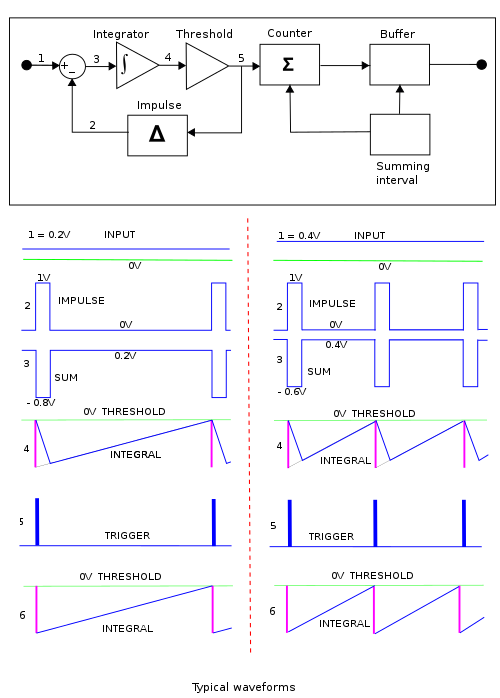
Chris, you asked: Here is an image from Stack Exchange (SE).
![]() and is this for low level AC measurement?
and is this for low level AC measurement?![]() especially if the "signal" is measuring AC power. Even tiny fluctuations in the AC waveform wreck havoc on the quality of the cal if the timing isn't very closely aligned between the device under test (like that AVR chip) and the reference
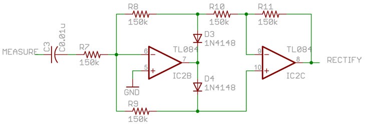
especially if the "signal" is measuring AC power. Even tiny fluctuations in the AC waveform wreck havoc on the quality of the cal if the timing isn't very closely aligned between the device under test (like that AVR chip) and the reference![]() Precision Rectifier: Yes, I would say "small signal" - a range from 5mV to 1.4Vp-p. The trick is AC and DC coupled versions of the circuit.
Precision Rectifier: Yes, I would say "small signal" - a range from 5mV to 1.4Vp-p. The trick is AC and DC coupled versions of the circuit.![]() so we're winding down here I think?
so we're winding down here I think?![]() I'll put a few resources in the chat
I'll put a few resources in the chat![]() Excellent Chris - you're the best!
Excellent Chris - you're the best!![]() I usually refer people to the EEVblog videos on op amps, I htink Dave did a good job with that stuff
I usually refer people to the EEVblog videos on op amps, I htink Dave did a good job with that stuff![]() vintage EEVblog, that is
vintage EEVblog, that is![]() haha
haha![]()
https://www.youtube.com/watch?v=Y0jkPLuFdnM
![]()
https://www.youtube.com/watch?v=7FYHt5XviKc
![]() as for books, Art of Electronics is ok
as for books, Art of Electronics is ok![]() but it's dense
but it's dense![]() Thanks Chris for your time
Thanks Chris for your time![]() flourless chocolate torte of electronics books
flourless chocolate torte of electronics books![]() OK, that was a neck-snappingly fast hour with Chris. Great stuff! I want to give Chris the opportunity to bow out if he needs to, but feel free to stick around and keep answering questions if you want to - don't think we'll run out any time soon. I'll just say an official thanks to Chris for a lively discussion and for spending time with us here on the Hack Chat.
OK, that was a neck-snappingly fast hour with Chris. Great stuff! I want to give Chris the opportunity to bow out if he needs to, but feel free to stick around and keep answering questions if you want to - don't think we'll run out any time soon. I'll just say an official thanks to Chris for a lively discussion and for spending time with us here on the Hack Chat.Don't forget that next week we'll be talking to Josh Lifton from Crowd Supply and crowdfunding your projects - https://hackaday.io/event/165483-crowd-supply-hack-chat-with-josh-lifton
![]() once you're past art of electronics, I Like "Design with Operational Amplifiers and Analog Integrated Circuits" by Sergio Franco
once you're past art of electronics, I Like "Design with Operational Amplifiers and Analog Integrated Circuits" by Sergio Franco![]()
https://www.amazon.com/Design-Operational-Amplifiers-Integrated-Circuits/dp/0072320842
Design with Operational Amplifiers and Analog Integrated Circuits
Franco's "Design with Operational Amplifiers and Analog Integrated Circuits, 3e" is intended for a design-oriented course in applications with operational amplifiers and analog ICs. It also serves as a comprehensive reference for practicing engineers. This new edition includes enhanced pedagogy (...
![]() And I'' be posting a transcript in case anyone missed anything. I know I did...
And I'' be posting a transcript in case anyone missed anything. I know I did...![]() Watch YouTube! Better than a book! ;-)
Watch YouTube! Better than a book! ;-)![]() Also shout out to the folks that taught me a lot of this stuff
Also shout out to the folks that taught me a lot of this stuff Keithley (now Tek) have a good book on measurements and signals called the Low Level Measurement Handbook (now in its 7th edition) https://download.tek.com/document/LowLevelHandbook_7Ed.pdf
![]() past that, read app notes and datasheets like it's your job
past that, read app notes and datasheets like it's your job![]() There was an old blogspot blog that followed along as the author read Jim Williams: http://readingjimwilliams.blogspot.com/p/best-app-notes.html
There was an old blogspot blog that followed along as the author read Jim Williams: http://readingjimwilliams.blogspot.com/p/best-app-notes.html![]() One book rec I'd love to add to the list: The Circuit Designer’s Companion
One book rec I'd love to add to the list: The Circuit Designer’s Companion![]() that's Kent Lundberg (@doctoranalog on twitter)
that's Kent Lundberg (@doctoranalog on twitter)![]() yeah, that one is ok as well. I recommend not getting the kindle verison
yeah, that one is ok as well. I recommend not getting the kindle verison![]() Oh the stuff by Hank Zumbahlen is also great, the Linear Circuit handbook
Oh the stuff by Hank Zumbahlen is also great, the Linear Circuit handbook![]()
https://www.analog.com/en/education/education-library/linear-circuit-design-handbook.html
Linear Circuit Design Handbook, 2008 | Education | Analog Devices
Linear Circuit Design Handbook, Edited by Hank Zumbahlen, Published by Newnes/Elsevier, 2008, ISBN-978-0-7506-8703-4 (Also published as Basic Linear Design, Analog Devices, 2007, ISBN-0-916550-28-1).Fundamentals and applications of data acquisition components. Contains much of the material covered in Data Conversion Handbook and Op Amp Applications
![]() I remember I found those PDFs bit by bit
I remember I found those PDFs bit by bit![]() thinking I was finding illegal copie
thinking I was finding illegal copie![]() s
s![]() nope, free book by ADI
nope, free book by ADI![]() haha
haha![]() I also interviewed Hank on The Amp Hour (my podcast with Dave Jones), he was great: https://theamphour.com/185-an-interview-with-hank-zumbahlen-zoppa-zumbahlen-zateticism/
I also interviewed Hank on The Amp Hour (my podcast with Dave Jones), he was great: https://theamphour.com/185-an-interview-with-hank-zumbahlen-zoppa-zumbahlen-zateticism/![]() Other analog folks I've interviewed:
Other analog folks I've interviewed:![]() if there's still time for a quick question - when you're designing analog stuff like this, do you jump straight into hardcore math or are you throwing up something that's like "this should more or less work" and then refining from there?
if there's still time for a quick question - when you're designing analog stuff like this, do you jump straight into hardcore math or are you throwing up something that's like "this should more or less work" and then refining from there?![]() Link to transcript: https://hackaday.io/event/165370-low-level-analog-measurement-hack-chat/log/165830-hack-chat-transcript-part-1
Link to transcript: https://hackaday.io/event/165370-low-level-analog-measurement-hack-chat/log/165830-hack-chat-transcript-part-1![]() and if it's math, do you have a recommendation of how to get better at that?
and if it's math, do you have a recommendation of how to get better at that?![]() https://theamphour.com/the-amp-hour-119-luculent-linear-legacy/
https://theamphour.com/the-amp-hour-119-luculent-linear-legacy/https://theamphour.com/the-amp-hour-77-winsome-waveform-wizardry/
https://theamphour.com/the-amp-hour-109-hexagram-hardware-holism/
https://theamphour.com/196-an-interview-with-mike-engelhardt-spice-simulator-synteresis/
https://theamphour.com/340-an-interview-with-jason-cerundolo/
https://theamphour.com/348-an-interview-with-art-kay/
https://theamphour.com/392-an-interview-with-matt-duff/
![]() > if there's still time for a quick question - when you're designing analog stuff like this, do you jump straight into hardcore math or are you throwing up something that's like "this should more or less work" and then refining from there?
> if there's still time for a quick question - when you're designing analog stuff like this, do you jump straight into hardcore math or are you throwing up something that's like "this should more or less work" and then refining from there?Honestly I'm normally copying an app note at the beginning. Borrowing knowledge from others at first and then really udnerstanding it when I'm hands on at the bench (or when things go wrong)
![]() starting from first principles and math is a good way to not get any circuits out into the world
starting from first principles and math is a good way to not get any circuits out into the world![]() but it's important to understand over time, IMO
but it's important to understand over time, IMO![]() as for how to get better at it, I've done it by putting myself into a situation where i need to understand it, that's the best motivator
as for how to get better at it, I've done it by putting myself into a situation where i need to understand it, that's the best motivator![]() which I realize isn't that helpful of an answer
which I realize isn't that helpful of an answer![]() nope it's very helpful. thank you!
nope it's very helpful. thank you!![]() OK, that's all from me, off to troubleshoot a circuit!
OK, that's all from me, off to troubleshoot a circuit!![]() thanks for stopping by to see my rambling!
thanks for stopping by to see my rambling! -
Hack Chat Transcript, Part 2
07/17/2019 at 20:03 • 0 comments![]() you need to have a good resistor and a good op amp
you need to have a good resistor and a good op amp![]() and there are a broad range of parts you can buy
and there are a broad range of parts you can buy![]() ...and a bypass cap across Rf.
...and a bypass cap across Rf.![]() so understanding the critical things will allow you to buy better components that allow more accurate readings
so understanding the critical things will allow you to buy better components that allow more accurate readings![]() any questions about that circuit?
any questions about that circuit?![]() in the case of that circuit, the resistor is super critical
in the case of that circuit, the resistor is super critical![]() if you imagine you have a resistor that is a different value than you think it is (say 1.2M instead of 1M), you can calibrate for it
if you imagine you have a resistor that is a different value than you think it is (say 1.2M instead of 1M), you can calibrate for it![]() In the event you would want to measure the current through the photodiode with a scope, are you looking at a 1% tolerance resistor or better?
In the event you would want to measure the current through the photodiode with a scope, are you looking at a 1% tolerance resistor or better?![]() but say you have a resistor that isn't perfectly linear
but say you have a resistor that isn't perfectly linear![]() then you can't really calibrate for that
then you can't really calibrate for that![]() @Chris Gammell last question from me: In your experience, how much does good/bad PCB design/layout contribute to the performance of the circuits we are talking about, qualitatively speaking of course.
@Chris Gammell last question from me: In your experience, how much does good/bad PCB design/layout contribute to the performance of the circuits we are talking about, qualitatively speaking of course.![]() > In the event you would want to measure the current through the photodiode with a scope, are you looking at a 1% tolerance resistor or better?
> In the event you would want to measure the current through the photodiode with a scope, are you looking at a 1% tolerance resistor or better?So you wouldn't be able to measure that current directly, a scope measures voltage
![]() Can you just use any high gain opamp? Is it critical?
Can you just use any high gain opamp? Is it critical?![]() but that circuit actually is a current-to-voltage converter
but that circuit actually is a current-to-voltage converter![]() @Dustin Sackett you can solve a lot of analog problems with the right capacitors between power and ground, as well as a very large ground plane.
@Dustin Sackett you can solve a lot of analog problems with the right capacitors between power and ground, as well as a very large ground plane.![]() I meant a series resistor you place in for test purposes only.
I meant a series resistor you place in for test purposes only.![]() so if you have a good resistor, you can say with confidence that you're looking at what the current is, represented by the voltage output from the op amp
so if you have a good resistor, you can say with confidence that you're looking at what the current is, represented by the voltage output from the op amp![]() > Can you just use any high gain opamp? Is it critical?
> Can you just use any high gain opamp? Is it critical?No, the other specs matter quite a bit
![]() if you have a high offset voltage between the inputs, that can impact things
if you have a high offset voltage between the inputs, that can impact things![]() the input bias current will have a large impact in this case as well
the input bias current will have a large impact in this case as well![]() > In your experience, how much does good/bad PCB design/layout contribute to the performance of the circuits we are talking about, qualitatively speaking of course.
> In your experience, how much does good/bad PCB design/layout contribute to the performance of the circuits we are talking about, qualitatively speaking of course.Using that example above again, it can be quite a bit
![]() if you have a poorly laid out circuit, it can really impact analog things
if you have a poorly laid out circuit, it can really impact analog things![]() much more than say an i2c bus
much more than say an i2c bus![]() but I'd say if you're in the microvolt range or below, then it'll be a bigger concern
but I'd say if you're in the microvolt range or below, then it'll be a bigger concern![]() as a general rule
as a general rule![]() similarly if you're in the nA of current measurement range, it'll have a big impact
similarly if you're in the nA of current measurement range, it'll have a big impact![]() but that also extends to cleanliness of the board as well
but that also extends to cleanliness of the board as well![]() In my experience, if I can make an analog circuit robust enough in a breadboard, then getting it to work on a PCB is relatively easy.
In my experience, if I can make an analog circuit robust enough in a breadboard, then getting it to work on a PCB is relatively easy.![]() any leakage path in an analog circuit is a potential place your circuit accuracy can get worse
any leakage path in an analog circuit is a potential place your circuit accuracy can get worse![]() > In my experience, if I can make an analog circuit robust enough in a breadboard, then getting it to work on a PCB is relatively easy.
> In my experience, if I can make an analog circuit robust enough in a breadboard, then getting it to work on a PCB is relatively easy.Yeah, agree with that
![]() there are definitely spots where a breadboard will start to breakdown
there are definitely spots where a breadboard will start to breakdown![]() usually 10MHz+ on the frequency side of things
usually 10MHz+ on the frequency side of things![]() Yes, parasitic capacitance
Yes, parasitic capacitance![]() and those same values above for voltage, current
and those same values above for voltage, current![]() Is that somewhat frequency dependent, both for the the analog signal of interest, and the related digital signals (SPI, I2C, etc)? If so, do you have a threshold for where things become trickier?
Is that somewhat frequency dependent, both for the the analog signal of interest, and the related digital signals (SPI, I2C, etc)? If so, do you have a threshold for where things become trickier?![]() ^^ I see your 10MHz comment now!
^^ I see your 10MHz comment now!![]() > Is that somewhat frequency dependent, both for the the analog signal of interest, and the related digital signals (SPI, I2C, etc)? If so, do you have a threshold for where things become trickier?
> Is that somewhat frequency dependent, both for the the analog signal of interest, and the related digital signals (SPI, I2C, etc)? If so, do you have a threshold for where things become trickier?For most things I was working on (and still work on when doing low level meausrement), it's a slow measurement
![]() High-speed stuff is a whole other world. I work in the audible range. Much easier.
High-speed stuff is a whole other world. I work in the audible range. Much easier.![]() if you get a DMM off a shelf
if you get a DMM off a shelf![]() and go to measure low level signals
and go to measure low level signals![]() say a 5.5 digit DMM
say a 5.5 digit DMM![]() if you're looking at the bottom of that range, uV measurements
if you're looking at the bottom of that range, uV measurements![]() you're normally integrating measurements over a long period to get more accuracy
you're normally integrating measurements over a long period to get more accuracy![]() so usually on the 1s scale
so usually on the 1s scale![]() depending on how fast you like seeing your digits dance around the screen
depending on how fast you like seeing your digits dance around the screen![]() what are you using for the integration over time?
what are you using for the integration over time?![]() > what are you using for the integration over time?
> what are you using for the integration over time?![]() In the DMM?
In the DMM?![]() that's built in, there are analog to digital converters that are averaging measurements
that's built in, there are analog to digital converters that are averaging measurements![]()
https://en.wikipedia.org/wiki/Delta-sigma_modulation
Delta-sigma modulation - Wikipedia
Delta-sigma ( ΔΣ; or sigma-delta, ΣΔ) modulation is a method for encoding analog signals into digital signals as found in an analog-to-digital converter (ADC). It is also used to convert high bit-count, low-frequency digital signals into lower bit-count, higher-frequency digital signals as part of the process to convert digital signals into analog as part of a digital-to-analog converter (DAC).
![]() Well, I would prefer to know how you would tease out a tiny signal from a noisy world using only discrete components.
Well, I would prefer to know how you would tease out a tiny signal from a noisy world using only discrete components.![]() that's a standard method for ADCs
that's a standard method for ADCs![]() passive discretes? Like Rs and Cs?
passive discretes? Like Rs and Cs?![]() Yes. And transistors, diodes are fine too. Just discrete component -- no chips
Yes. And transistors, diodes are fine too. Just discrete component -- no chips![]() It explains the principle better
It explains the principle better![]() Like stages of filters
Like stages of filters![]() transistors and diodes are active, so that's what I wnated to deliniate
transistors and diodes are active, so that's what I wnated to deliniate![]() putting power into a system to help amplify is an important distinction
putting power into a system to help amplify is an important distinction![]() short answer for 2019: I wouldn't
short answer for 2019: I wouldn't![]() discrete components are fun, but there are so many better tools out there
discrete components are fun, but there are so many better tools out there![]() if I was going to study to go and design chips for the industry, I'd be doing more transistor level design
if I was going to study to go and design chips for the industry, I'd be doing more transistor level design![]() Understood, but it's hard to grasp what the "other tools" are doing inside of that black box.
Understood, but it's hard to grasp what the "other tools" are doing inside of that black box.![]() I see!
I see!![]() yeah, it's frustrating sometimes
yeah, it's frustrating sometimes![]() and understanding the underlying architectures can help
and understanding the underlying architectures can help![]() understanding what's happening at the input to an op amp, for instance
understanding what's happening at the input to an op amp, for instance![]() That's the benefit of discrete component examples (active, passive, makes no difference -- just out in the open. Not black box)
That's the benefit of discrete component examples (active, passive, makes no difference -- just out in the open. Not black box)![]() there are diodes in there which can mess up your measurements sometimes
there are diodes in there which can mess up your measurements sometimes![]() How so?
How so?![]() as you get closer to the rails, it's possible to get "stuck"
as you get closer to the rails, it's possible to get "stuck"![]() Due to the voltage drop?
Due to the voltage drop?![]() Excellent points Chris! (ADC, sampling, PCB layout, measurement repeatability/accuracy)!!!
Excellent points Chris! (ADC, sampling, PCB layout, measurement repeatability/accuracy)!!!![]() so if you have an op amp with +/-15V rails, I normally would try and keep the incoming signals between +/-10V
so if you have an op amp with +/-15V rails, I normally would try and keep the incoming signals between +/-10V![]() this has gotten better on modern parts
this has gotten better on modern parts![]() but old parts, this was a big issue
but old parts, this was a big issue![]() Stay away from the rails = "Mind the gap" LOL
Stay away from the rails = "Mind the gap" LOL![]() haha
haha![]() yeah
yeah![]() So rule of thumb -- give your parts 30% more power than your signal?
So rule of thumb -- give your parts 30% more power than your signal?![]() so if I went and built up an op amp from transistors (possible), I'd have to deal with a lot of the issues that op amp designers have dealt with for years (and improved)
so if I went and built up an op amp from transistors (possible), I'd have to deal with a lot of the issues that op amp designers have dealt with for years (and improved)![]() > So rule of thumb -- give your parts 30% more power than your signal?
> So rule of thumb -- give your parts 30% more power than your signal?No, I wouldn't say that. It's more "read the datasheet"
![]() and find parts that optimize your signal chain
and find parts that optimize your signal chain![]() Of course
Of course![]() "Read the datasheet"
"Read the datasheet"We need t-shirts
![]() yeah, kind of like the RTFM stickers from Sparkfun
yeah, kind of like the RTFM stickers from Sparkfun![]() Are a lot of people in here using analog signal processing in their projects?
Are a lot of people in here using analog signal processing in their projects?![]() @Chris Gammell Thanks for getting into the weeds. You can return to fancy expensive equipment
@Chris Gammell Thanks for getting into the weeds. You can return to fancy expensive equipment![]() would love to get a sampling of what people are currently doing
would love to get a sampling of what people are currently doing![]() or looking to do
or looking to do![]() > so if you have an op amp with +/-15V rails, I normally would try and keep the incoming signals between +/-10V
> so if you have an op amp with +/-15V rails, I normally would try and keep the incoming signals between +/-10VRail to rail or bust. Who cares about money? :)
![]() also, let's hear it for the Hackaday crew in the house! Thanks @Mike Szczys and @Dan Maloney!
also, let's hear it for the Hackaday crew in the house! Thanks @Mike Szczys and @Dan Maloney!![]() thanks!
thanks!![]() Would you recommend the art of electronics to learn more about analog circuit design?
Would you recommend the art of electronics to learn more about analog circuit design?![]() On the tips and tricks front. What sort of DFM tricks do you roll into your analog designs? Any sort of calibration at manufacture time concerns, for example?
On the tips and tricks front. What sort of DFM tricks do you roll into your analog designs? Any sort of calibration at manufacture time concerns, for example?![]() @Dan Maloney does an excellent job with the Hack Chats, nice work! And thanks to @Chris Gammell and a million others for hosting!
@Dan Maloney does an excellent job with the Hack Chats, nice work! And thanks to @Chris Gammell and a million others for hosting!![]() FWIW my utility for "low level" design is more in characterization of more commonplace designs, without having to buy a $32342342311 SMU or power analyzer.
FWIW my utility for "low level" design is more in characterization of more commonplace designs, without having to buy a $32342342311 SMU or power analyzer.![]() Chris, I'm working on a "precision rectifier" circuit also known as a "super diode". A diode and op amp (to be sampled by an ADC).
Chris, I'm working on a "precision rectifier" circuit also known as a "super diode". A diode and op amp (to be sampled by an ADC).![]() When I think "low level measurement" I think more "CurrentRanger" and less analog design.
When I think "low level measurement" I think more "CurrentRanger" and less analog design.![]() > Would you recommend the art of electronics to learn more about analog circuit design?
> Would you recommend the art of electronics to learn more about analog circuit design?Depends on your goals. AoE is a good overview, but ther are lots of good books out there. Jim Williams app notes are free
![]() or you can read the "Analog Circuit Design" books from Newnes
or you can read the "Analog Circuit Design" books from Newnes![]() which are just compiled versions of those things
which are just compiled versions of those things![]() I'm working on a DIY CO detector using a sensor like this:
I'm working on a DIY CO detector using a sensor like this:https://www.sparkfun.com/products/9403
![]() > On the tips and tricks front. What sort of DFM tricks do you roll into your analog designs? Any sort of calibration at manufacture time concerns, for example?
> On the tips and tricks front. What sort of DFM tricks do you roll into your analog designs? Any sort of calibration at manufacture time concerns, for example?As Mike Harrison said on Embedded.fm this week, "You can never have too many test points"
![]() I'm actually going through your 'Getting to Blinky 4.0' playlist now so I can design it in KiCAD.
I'm actually going through your 'Getting to Blinky 4.0' playlist now so I can design it in KiCAD.![]() killer episode, btw: https://embedded.fm/episodes/294
killer episode, btw: https://embedded.fm/episodes/294![]() As for other calibration things, the best tip is to not need it
As for other calibration things, the best tip is to not need it![]() so if you can pay that extra dollar for a high accuracy resistor, pay for it
so if you can pay that extra dollar for a high accuracy resistor, pay for it![]() calibration is expensive
calibration is expensive![]() and it sucks
and it sucks![]() so balance it with the overall cost of the product
so balance it with the overall cost of the product![]() aside from that, hire great manufacturing engineers like @monk :-D
aside from that, hire great manufacturing engineers like @monk :-D![]() "I need more test points" another great shirt idea -- perfect for FW and Manufacturing engineerings ;)
"I need more test points" another great shirt idea -- perfect for FW and Manufacturing engineerings ;)Hack Chat Transcript, Part 1 07/17/2019 at 20:02 • 0 comments
![]() Hello Hack Chat!
Hello Hack Chat!![]() Hi Chris - welcome!
Hi Chris - welcome!![]() thanks!
thanks!![]() oh heeeey
oh heeeey![]() Hey Morgan
Hey Morgan![]() Hi!
Hi!![]() Looks like we've got a good turnout, so let's kick it off. Welcome to the Hack Chat everyone, thanks for coming, and thanks to Chris Gammell for hosting. When Chris suggested low-level analog measurement as a topic, I jumped at it - figured we'd all love to hear about that.
Looks like we've got a good turnout, so let's kick it off. Welcome to the Hack Chat everyone, thanks for coming, and thanks to Chris Gammell for hosting. When Chris suggested low-level analog measurement as a topic, I jumped at it - figured we'd all love to hear about that.Take it away, Chris!
![]() OK!
OK!![]() so uh
so uh![]() Analog signals
Analog signals![]() are everywhere!
are everywhere!![]() how low level are we talking here?
how low level are we talking here?![]() obviously you all knew that
obviously you all knew that![]() so maybe I'll step back
so maybe I'll step back![]() and mention a bit about my background
and mention a bit about my background![]() and why I thought this might be a good topic
and why I thought this might be a good topic![]() I went to school for electronics and struggled with it
I went to school for electronics and struggled with it![]() still do, some days
still do, some days![]() but then I had the opportunity to work at Keithley Instruments in Cleveland OH
but then I had the opportunity to work at Keithley Instruments in Cleveland OH![]() and that's where I really got an education in electronics
and that's where I really got an education in electronics![]() that was working on supporting things like the 2400 source meter, 6517B electrometer, 6485 current source, etc
that was working on supporting things like the 2400 source meter, 6517B electrometer, 6485 current source, etc![]() of course, that's been a while now since I was ther
of course, that's been a while now since I was ther![]() but the low level measurement stuff sticks with you
but the low level measurement stuff sticks with you![]() namely working with signal processing in the analog domain
namely working with signal processing in the analog domain![]() working with op amps, resistors, capacitors, etc
working with op amps, resistors, capacitors, etc![]() What signal to noise ratio?
What signal to noise ratio?![]() and there are a lot of things to consider
and there are a lot of things to consider![]() like power cleanliness and such
like power cleanliness and such![]() and very in depth topics for test and measurement
and very in depth topics for test and measurement![]() but that was the genesis of thinking it'd make a good hack chat topic
but that was the genesis of thinking it'd make a good hack chat topic![]() since then, I mostly work on systems that are sensing something in the real world
since then, I mostly work on systems that are sensing something in the real world![]() but usually are piping back data over an i2c or SPI bus
but usually are piping back data over an i2c or SPI bus![]() so there's less direct interaction with analog signals
so there's less direct interaction with analog signals![]() but most people still need to think about things in terms of analog signals and how they look to the chips they're interacting with
but most people still need to think about things in terms of analog signals and how they look to the chips they're interacting with![]() so I guess there are some general tips and tricks, but not sure if that's what people are interested in
so I guess there are some general tips and tricks, but not sure if that's what people are interested in![]() or if they have specific questions they'd like me to answer
or if they have specific questions they'd like me to answer![]() but I'm happy to do either
but I'm happy to do either![]() and can fill in as necessary
and can fill in as necessary![]() from a day-to-day basis, I think about troubleshooting and how the interaction with the analog side of things impacted me
from a day-to-day basis, I think about troubleshooting and how the interaction with the analog side of things impacted me![]() If you had a "Top X tips and tricks" to recommend, that pertain to this subject, that might be cool!
If you had a "Top X tips and tricks" to recommend, that pertain to this subject, that might be cool!![]() why don't you give us an example description of a circuit you have used to buffer a signal?
why don't you give us an example description of a circuit you have used to buffer a signal?![]() so on the tips and tricks side of things
so on the tips and tricks side of things![]() I'm always pulling out a scope first and foremost
I'm always pulling out a scope first and foremost![]() and checking the rails
and checking the rails![]() obviously the voltage levels
obviously the voltage levels![]() but also how consisten, or "clean", the power supply looks
but also how consisten, or "clean", the power supply looks![]() this also usually allows me to check if I've turned the device in question on
this also usually allows me to check if I've turned the device in question on![]() which is a pretty common problem as well
which is a pretty common problem as well![]() :-D
:-D![]() also, if you had some solid book or other resource recommendations on the subject, maybe both historically, as well as current day
also, if you had some solid book or other resource recommendations on the subject, maybe both historically, as well as current day![]() once I know the power source is looking good, I'm usually pulling out a schematic and writing down the signals and levels I expect to see, BEFORE probing the circuit
once I know the power source is looking good, I'm usually pulling out a schematic and writing down the signals and levels I expect to see, BEFORE probing the circuit![]() How do you juge that ? Maybe it's just me, but even measuring a _battery_ I can see noise spikes .... (coming from the environment presumably). So what's the proper way to measure a rail and make sure you see the rail itself and not ... the room.
How do you juge that ? Maybe it's just me, but even measuring a _battery_ I can see noise spikes .... (coming from the environment presumably). So what's the proper way to measure a rail and make sure you see the rail itself and not ... the room.![]() it's important to create some mental models of what you expect to see before you actually start probing around
it's important to create some mental models of what you expect to see before you actually start probing around![]() How much does power supply cleanliness affect readings e.g. if I'm using an opamp to buffer a signal, what should I do in respect of the opamp power rails?
How much does power supply cleanliness affect readings e.g. if I'm using an opamp to buffer a signal, what should I do in respect of the opamp power rails?![]() I don't know about you, but my brain will do backflips to say, "That looks right-ish"
I don't know about you, but my brain will do backflips to say, "That looks right-ish"![]() > How do you juge that ? Maybe it's just me, but even measuring a _battery_ I can see noise spikes ....
> How do you juge that ? Maybe it's just me, but even measuring a _battery_ I can see noise spikes ....Well if it's on a battery and you see spikes, something is wrong
![]() so in that case, I'd isolate the battery by itself
so in that case, I'd isolate the battery by itself![]() I expect to not see any spikes
I expect to not see any spikes![]() but if the battery by itself does...uh...bad battery!
but if the battery by itself does...uh...bad battery!![]() also, run away!
also, run away!![]() @Dustin Sackett Keith Hemingway's "Electronic Designer's Handbook" is clear and has some useful tips
@Dustin Sackett Keith Hemingway's "Electronic Designer's Handbook" is clear and has some useful tips![]()
https://media1.giphy.com/media/e1Lv6Gvd8bFFC/source.gif
Run Away Monty Python GIF - Find & Share on GIPHY
Discover & share this Run Away GIF with everyone you know. GIPHY is how you search, share, discover, and create GIFs.
![]() No, I expect it's coming from the scope or picking up LED lighting or something. But that's the issue, the environment is not noise free and I end up measuring that rather than the rail itself it seems.
No, I expect it's coming from the scope or picking up LED lighting or something. But that's the issue, the environment is not noise free and I end up measuring that rather than the rail itself it seems.![]() > How much does power supply cleanliness affect readings e.g. if I'm using an opamp to buffer a signal, what should I do in respect of the opamp power rails?
> How much does power supply cleanliness affect readings e.g. if I'm using an opamp to buffer a signal, what should I do in respect of the opamp power rails?Could be quite a bit! If you have a bunch of AC noise that gets rectified, it'll look like the DC signal is higher than it actually is
![]() thank you @Kelly Heaton , cheap and looks exhaustive! I will check that out
thank you @Kelly Heaton , cheap and looks exhaustive! I will check that out![]() > No, I expect it's coming from the scope or picking up LED lighting or something. But that's the issue, the environment is not noise free and I end up measuring that rather than the rail itself it seems.
> No, I expect it's coming from the scope or picking up LED lighting or something. But that's the issue, the environment is not noise free and I end up measuring that rather than the rail itself it seems.Sure, the environment can really impact things
![]() but it's all about isolation and mental models
but it's all about isolation and mental models![]() what do you expect to see -> What do you actually see -> Why is that happening -> can you isolate it
what do you expect to see -> What do you actually see -> Why is that happening -> can you isolate it![]() @duddy it's much easier to understand than the Bible (Art of Electronics by Horrowitz and Hill, which you need to own anyway even just to lift weights)
@duddy it's much easier to understand than the Bible (Art of Electronics by Horrowitz and Hill, which you need to own anyway even just to lift weights)![]() in terms of isolating different parts of the circuit, I'm usually designing in 0 ohm resistor severywhere
in terms of isolating different parts of the circuit, I'm usually designing in 0 ohm resistor severywhere![]() so I can swap in a low value resistor to look at current
so I can swap in a low value resistor to look at current![]() or to pull it entirely and isolate that part of the circuit
or to pull it entirely and isolate that part of the circuit![]() Is it enough to take power from an SMPS, run it through a linear regulator and put a decoupling cap on there? Or is there more to do?
Is it enough to take power from an SMPS, run it through a linear regulator and put a decoupling cap on there? Or is there more to do?![]() I was tutoring someone recently and the 0 ohm resistor thing was a new thing to them
I was tutoring someone recently and the 0 ohm resistor thing was a new thing to them![]() @Chris Gammell could you give a general recommendation on the design process for a high end low-level analog circuits?
@Chris Gammell could you give a general recommendation on the design process for a high end low-level analog circuits?![]() @Chris Gammell 0 ohm resistor?
@Chris Gammell 0 ohm resistor?![]() and of course, we all start somewhere! That's a huge part of my design process now, knowing how to unhook things from the rest of the ciricuit
and of course, we all start somewhere! That's a huge part of my design process now, knowing how to unhook things from the rest of the ciricuit![]() 0 ohm resistor = SMD jumper ;)
0 ohm resistor = SMD jumper ;)![]() > Is it enough to take power from an SMPS, run it through a linear regulator and put a decoupling cap on there? Or is there more to do?
> Is it enough to take power from an SMPS, run it through a linear regulator and put a decoupling cap on there? Or is there more to do?Depends on your application
![]() sometimes that's all you have available
sometimes that's all you have available![]() > 0 ohm resistor = SMD jumper ;)
> 0 ohm resistor = SMD jumper ;)And that's right! they're called a few different things
![]() @Seth ha
@Seth ha![]() but adding in different "options" in a circuit can really help
but adding in different "options" in a circuit can really help![]() but jumpers are sometimes designed into the PCB
but jumpers are sometimes designed into the PCB![]() I want to clarify that's not what I normally do
I want to clarify that's not what I normally do![]() @Kelly Heaton have that Bible you speak of! I never heard about it throughout my education, and saw it recommended on here! :)
@Kelly Heaton have that Bible you speak of! I never heard about it throughout my education, and saw it recommended on here! :)![]() I'll design a 0 ohm resistor into the signal path
I'll design a 0 ohm resistor into the signal path![]() and then it's an option when i'm troubleshooting
and then it's an option when i'm troubleshooting![]() > could you give a general recommendation on the design process for a high end low-level analog circuits?
> could you give a general recommendation on the design process for a high end low-level analog circuits?@Dustin Sackett that's a pretty broad ask :-D
![]() like...unlimited budget?
like...unlimited budget?![]() that's another thing to note about analog
that's another thing to note about analog![]() most people don't do it because it's expensive as heck
most people don't do it because it's expensive as heck![]() like watch Shahriar or Dave Jones or anyone opening test equipment
like watch Shahriar or Dave Jones or anyone opening test equipment![]() and you'll see things like...a $5 resistor!
and you'll see things like...a $5 resistor!![]() well, maybe just a workflow summary
well, maybe just a workflow summary![]() @Chris Gammell I do it because its dirt cheap!
@Chris Gammell I do it because its dirt cheap!![]() I used to work with a 1 TOhm resistor at Keithely
I used to work with a 1 TOhm resistor at Keithely![]() it was bananas
it was bananas![]() and it was really accurate too
and it was really accurate too![]() but usually you'll end up paying for good components
but usually you'll end up paying for good components![]() Geeze, a humid room is less than 1Tohm! Hahaha
Geeze, a humid room is less than 1Tohm! Hahaha![]() so I suppose another thing is understanding the differences between accuracy, precision and repeatability.
so I suppose another thing is understanding the differences between accuracy, precision and repeatability.![]() Napkin sketch>Schematic>Simulation>breadboard (? mixed reviews on this)>PCB layout?
Napkin sketch>Schematic>Simulation>breadboard (? mixed reviews on this)>PCB layout?![]()
![]() Excellent points Chris, "Look for clean", "Check the rails", "Isolate using 0 ohm". Keep going!
Excellent points Chris, "Look for clean", "Check the rails", "Isolate using 0 ohm". Keep going!![]() so let's look at a simple circuit
so let's look at a simple circuit![]() that's a cool diagram!
that's a cool diagram!![]()
![]() like a simple circuit, right?
like a simple circuit, right?![]() it's basically measuring the current coming out of (going into) a photodiode
it's basically measuring the current coming out of (going into) a photodiode![]() but in the three things in that circuit, there's not much you can control
but in the three things in that circuit, there's not much you can control![]() so if you want a truly accurate circuit
so if you want a truly accurate circuitAbout Us Contact Hackaday.io Give Feedback Terms of Use Privacy Policy Hackaday API
Low-Level Analog Measurement Hack Chat
Chris Gammell measures his Analog Life


 OK, that was a neck-snappingly fast hour with Chris. Great stuff! I want to give Chris the opportunity to bow out if he needs to, but feel free to stick around and keep answering questions if you want to - don't think we'll run out any time soon. I'll just say an official thanks to Chris for a lively discussion and for spending time with us here on the Hack Chat.
%2c445%2c291%2c400%2c400%2carial%2c12%2c4%2c0%2c0%2c5_SCLZZZZZZZ_.jpg)

 Link to transcript: