Array design
Sound array can be constructed in infinite amount of ways. It consists of receiver elements, typically microphones or piezo elements. The array can also acts as a transmitter, if the elements can send and receive (sound) waves. Piezo's have an interesting feature. When current is sent through a piezo element, it expands ie. it transforms electrical current into movement, just like a loudspeaker. But if the element is exposed to waves, it generates current, just like a microphone.
A simple array is just a 1D array, where elements are placed with equal distances. The introduction video shows this quite nicely.
There are several properties that influences the way the array works.
- Element spacing
- Frequency
- Sound speed
Above allows us to calculate the time-delay that has to be applied to the signal sent to each of the elements, to effectively send sound in a specific direction.
Likewise, the same time-delay is part of the audio signal that is received by the microphones.
Parameters to consider:
- Frequency can only vary slightly, meaning, "ping" sent by the transmitter signal must have a relative narrow band. Example is F=40kHz, like the well known ultrasound transmitter (SR04). However, some pulses can have a frequency sweep (FM), where frequency sweeps from 38kHz to 42kHz.
- If frequency varies too much, the angle-phase changes and we cannot derive where sound is coming from
- Sound speed can be considered (relatively) constant. 330m/s in air and 1500m/s in water.
- Element spacing. There is a "golden rule of thumb". d = wavelength/2, where d can be slightly higher, but that introduces grating lopes in the beam radiation pattern.
- Element spacing around 2cm for air and frequency around 10kHz is ok.
- Element spacing around 1cm for air and frequency around 20kHz is ok.
- Element spacing for sonars, using 400kHz, an element spacing must be around 1-2mm.
- Open-angle, meaning the widest angle that we can beamform is oa = wavelength/d (in radians). Example oa=330m/s / 10kHz / 2cm = 165 degrees ie. a swath of +/- 80 degrees.
- The more elements, the narrower beams, the better image resolution when we start drawing maps based on sonar pings (imaging sonar). 8 elements are not enough to map, but can be used as detection. 16 elements can show recognisable features. 32 is 2x better than 16 and so on. 256 og 512 generate great looking images. Ultrasound scanners use 40-60 elements.
- 2D arrays, seen in ultrasound can generate awesome looking 3D images. They could have 60x60 elements and run in GHz frequencies, so beams are ultra narrow, but at short range.
- The lower frequency, the longer range. Whales, sending out sound in the 500-5kHz range (audible) can be heard thousands of kilometers away. GHz arrays have a range in cm scale.
For my project i have several arrays:
- 1D 16 element, d=2.05cm. Works fine in 10kHz frequency
- 1D 24 element, d=1.02cm. Works fine in 20kHz frequency.
- 2D 5x5 elements, d=1.02cm.
- 1D 4 element transmitter, d=1.6cm. Works best under 20kHz. Above we get grating lopes above +/-70 deg. So, at 22kHz, as long as we transmit frequencies 18kHz-22kHz at angles below +/-70 deg, we are good. Beam width is around +/-15 deg. I plan on an experiment where I transmit 4 pulses, in the vertical plane and beam form each one on a 4x 30 deg swath (with some overlapping), hopefully we get a pseudo 3D image using on 2x 1D arrays.
The following array is the 1D 24 channel array.

The beam radiation pattern for the 1D 24 channel array.
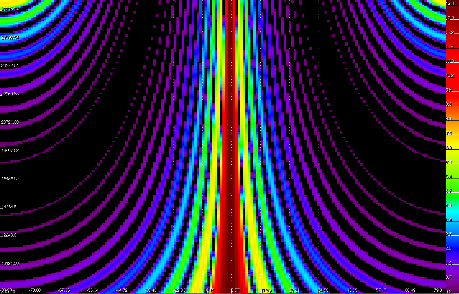
Color scale is the intensity. X-axis is the angle and Y-axis is the frequency of the pulse. The lower the frequency, the wider the beam is. The higher frequency, grating lopes starts to appear.
Selecting the frequency to 24kHz, we can plot the intensity

Beam width at 24kHz is around +/- 3 deg. At 1m each beam will be 5cm wide. At 10m beams are 50cm. So, its important to get as narrow a beam as possible if we want to map details on objects at longer distances.
The 2D array

The above array is missing one element (center element). A full array would require 25 channels, but since I only have 24 channels, I need to take this into account when designing the array.
Since element spacing is the same as in the 1D array, a good starting point to use the 1D beam pattern to identify what frequency is optimal.
Here we can see that the 24kHz is a bit too high. Grating lopes are starting to influence the final result. It's probably better to lower frequency to around 21kHz.

Using only 5 elements in both directions, that resulting pattern is a wide main lope (+/- 15deg) and side lopes that will create more blurry effect on the final images. But they will be in 3D!!! Much like the time-of-flight cameras, with visual combined with laser scanners. Or a 2D LIDAR, if that even exist.
Getting higher resolution is achieved by adding more channels. Ultrasonic scanners that can scan in 3D, they have 60x60 elements or more and the distance to the target is close, in cm range.
Random element arrays
If you have limited number of elements, and you want to get some of the properties of larger arrays, like narrow beams, we can achieve this by only using a randomly placed elements in the larger array. The benefit is narrow beams but the cost is side lopes that are not dampened as much.
2D array 8x8 using only 24 elements, randomly placed
Beam pattern
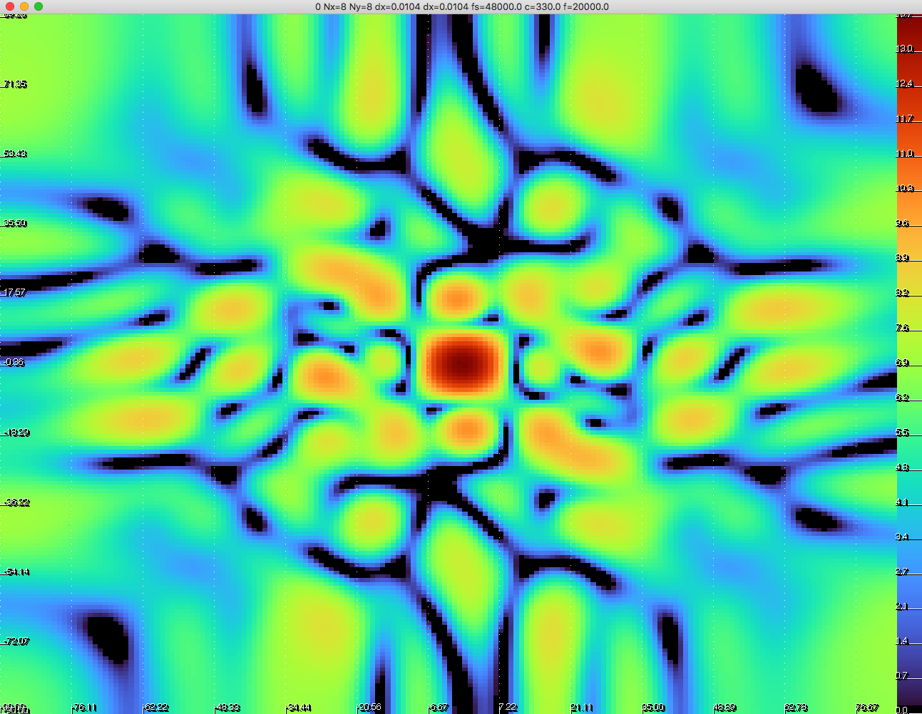
As we can see, the side lopes have much higher intensity, but main lope is narrow. If this is a good idea, we will have to see. Its definitely something that I am going to try.
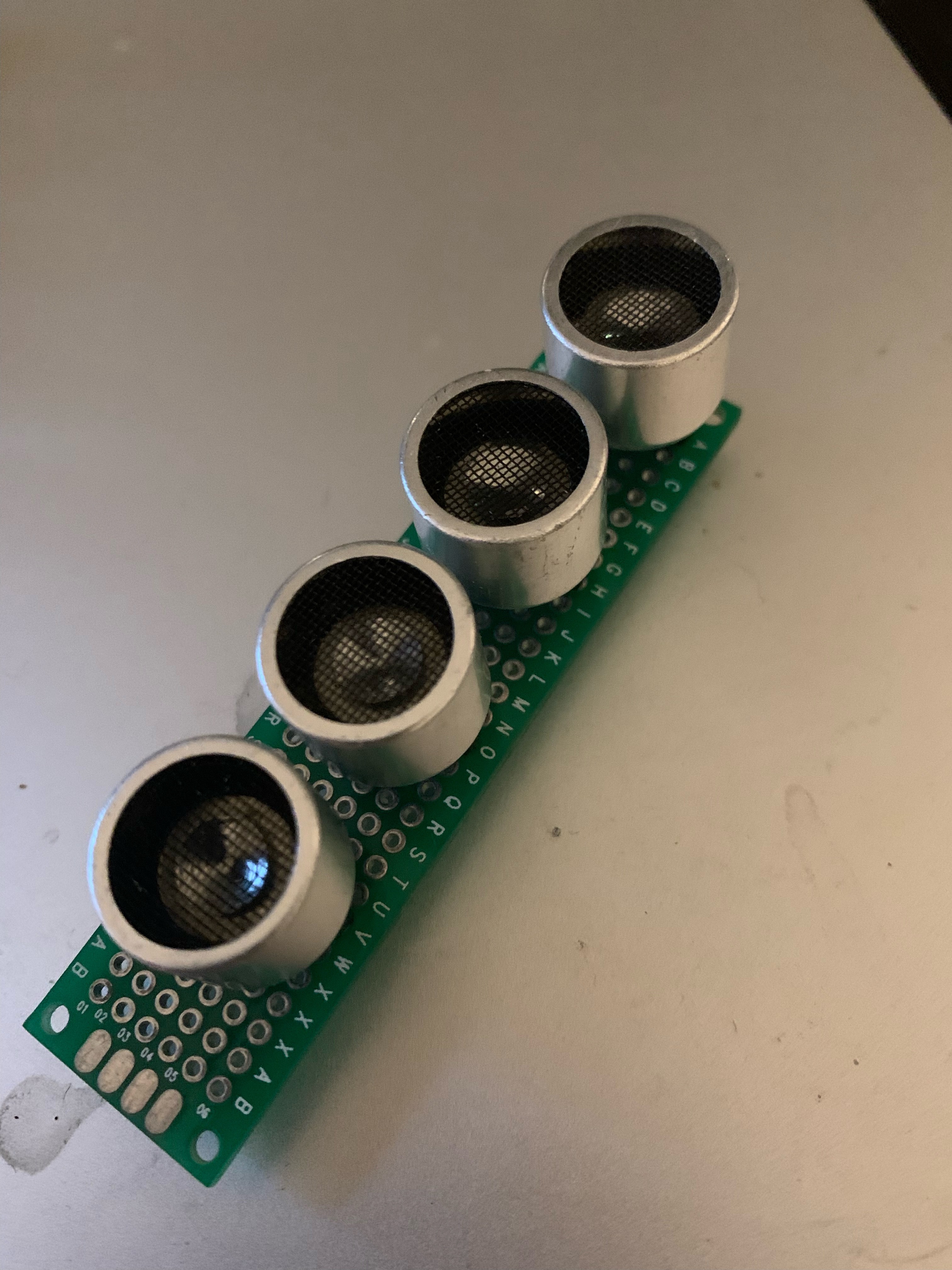
Transmitter 1D 4 channel array
The transmitter array will be used to actively steer the beams in the vertical direction. The transmitter will focus energy in a vertical angles for example, it can be steered to a downwards angle of -30 deg. Receiver elements will only receive echos from the direction where the pulse is steered.
Prototype array for directional transmitter
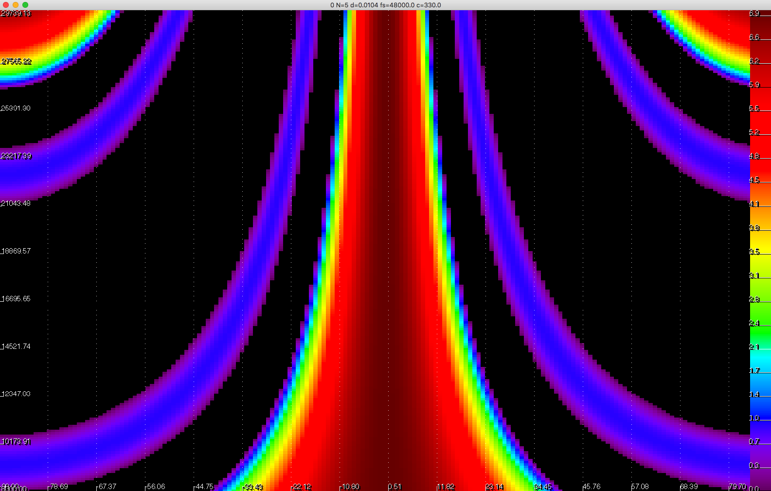
Beam pattern of the directional transmitter
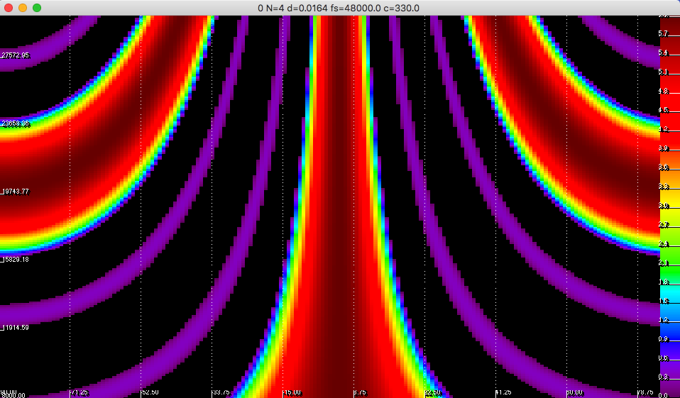
If signal is transmitted around 12kHz or less, grating lopes should be avoided.
Beam pattern at frequency of 12kHz
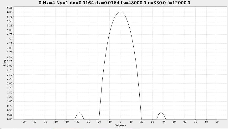
Beam is wide, approx +/- 20 deg.
Scanning of the vertical area could be in 20deg. steps, with overlapping.
Discussions
Become a Hackaday.io Member
Create an account to leave a comment. Already have an account? Log In.