- The logical circuit in the bottom right allows to drive three digits depending on the states of only two pins PB3 and PB4.
- The capacitor circuit allows to couple the clock and reset lines of the counters on a single avr pin, PB1. A long 1 signal will load the capacitor and trigger the reset signal. A diode was necessary but I don't really know why actually...
- PB0 select the counter to enable, A or B.
- Measurement of the voltage is done on PB2.
- (Sorry if this is a bit succinct, this my first post ever on a website...)
- (I also hope that the .sch file is correct, I am also new to KiCad...)
- I added the part of the circuit that is being measure: a linear voltage regulator that I feed with a laptop charger output (~18V). Another regulator provides the 5V for the AVR
0%
0%
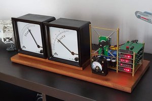
Voltmeter
Simple voltmeter using an Attiny85 and a dual counter to drive the 3x7 segments display
Become a Hackaday.io member
Already have an account? Log in.
Just one more thing
To make the experience fit your profile, pick a username and tell us what interests you.
Pick an awesome username
hackaday.io/
Your profile's URL: hackaday.io/username. Max 25 alphanumeric characters.
Pick a few interests
Projects that share your interests
People that share your interests


 Yann Guidon / YGDES
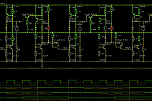
 Christian
Sorry, it's actually fed through a voltage divider that is not on the schematics. You have to make sure it's not gonna be over the 5V of Vcc (mine is coming from a laptop transformer that provides ~18V). If I have time next week, I may draw the remaining parts in Kicad too. And I'll add png and svg files for the circuit.