 Eric Hertz
I figured there must be a better way to handle the trigger-handler circuitry... here's what we had before (see previous logs):
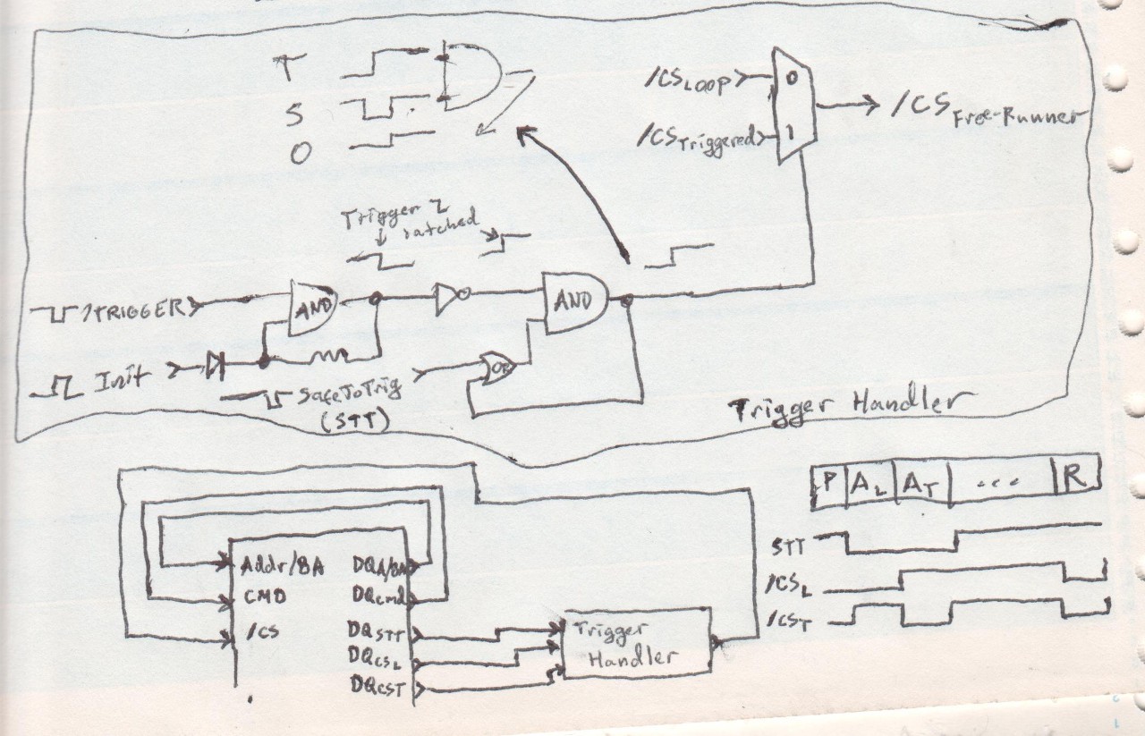
The problem is, again, briefly... the MUX, alone, cannot be switched at certain times, otherwise we'll get either TWO Activate-Row commands or ZERO, depending, as I recall, on whether trigger goes from low to high or high to low... Neither of which is acceptable, and will kill free-running. Without the "Safe To Trigger" circuitry, the odds would be *rare*, only 1/256, at worst. But that isn't good enough for me. So, the addition of "Safe To Trigger" signal and the AND/OR "latch".
Looked into it a bit again tonight, and came across a brief-thought that I drew-up, then brushed-off early-on...
I'll come back to that in a second...
Per the last log, the MUX could be implemented with an "AND-OR-INVERT" and an additional inverter:
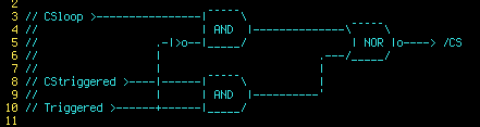
(This is very similar to how #sdramThing4.5 "Logic Analyzer" switched between Sample and Repeat modes)
Note that the input CS signals are active-high, but the output active-low... That's fine, just a minor software-change.
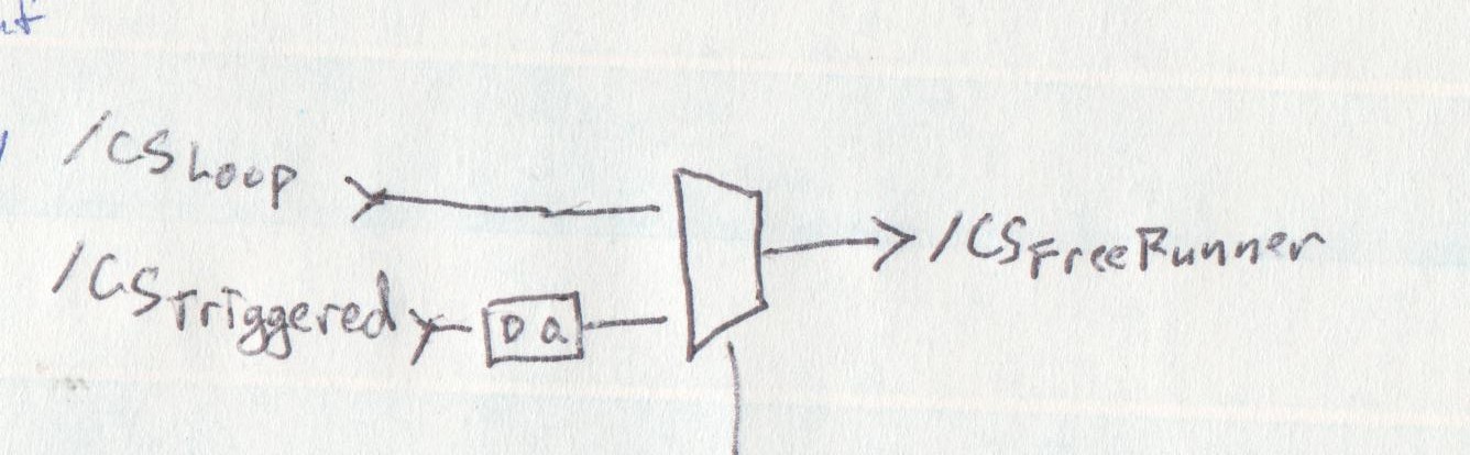
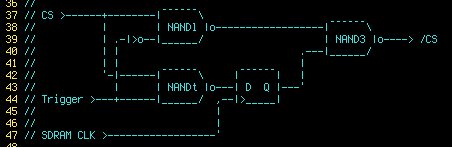
I guess that brief-sketch caught my attention... so I thought "what if I throw a single DQ latch *within* the AND-OR-INVERT, on a single branch...
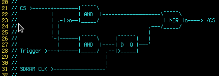
Note that I can now use the same CS(input) signal to drive the thing... depending on which level the Trigger input is at, we'll either get a /CS alongside "Activate-Row Triggered" or "Activate-Row Loop" (shown as "At" and "Al" in the first drawing). Cool!
And, on top of that... I *think* doing it this way assures there's no case where a Trigger input could possibly cause *both* or *neither* At/Al. AWESOME.
That removes the need for "Safe To Trigger", removes the need for an additional CS signal, and removes the necessity for quite a bit of circuitry.
All we need, now, is a simple set/reset latch fed by our trigger-pulse and driving the "Trigger" input of our "MUX"... which, I guess now is more of a "selectable delay."
--------
Note that, as my brain's working now, I'm pretty certain putting the DQ-latch *within* the AND-OR-INVERT is the key factor that makes this work... different than putting it on the CS input to that AND-branch. Were it to be on the *input*, there'd be a case where the trigger could occur precisely at the time when CS would be active on the pre-triggered branch, then active *again* (delayed) for the next branch. Putting the DQ-latch *within* a branch should remove that risk, because it will load CS-inactive when the actual CS-input is active, and thus even if the trigger occurs at that same precise time, the DQ-latch will have already loaded CS-inactive, as "masked" by the AND-gate.
--------
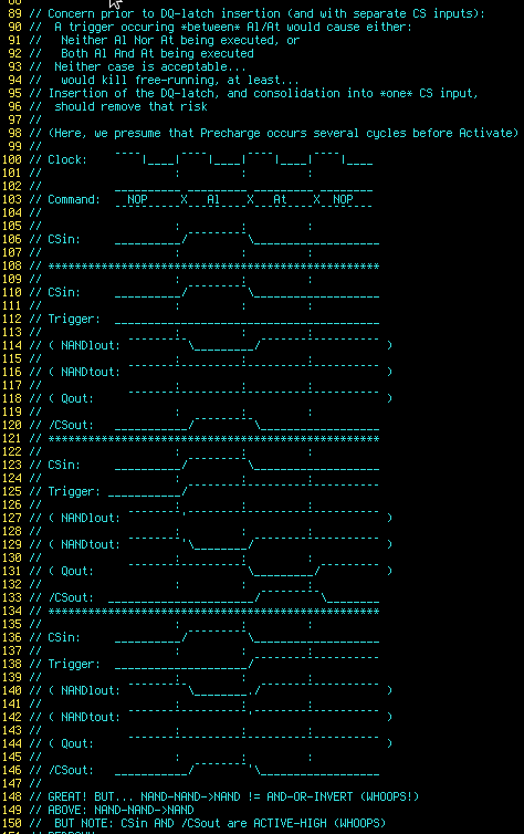
I drew up timing-diagrams and it seemed to work out perfectly... Then I redrew them with what I thought was the NAND-equivalent, and everything went haywire... Hours of haywire and no solution...
So, now I'm left with what I think is NAND-eqivalent with CS in/out active-high, which means I need an inverter on the output...
...
Oh, and here's the bit showing how the Free-Runner handles the circular-prebuffer, and where it jumps after a trigger is detected. This shows a Two-Bank SDRAM, whereas some are four... (Note the two different "Trigger-Detected" jump-points, due to two banks... I'll explain later). The concept, whether the device has two banks or four, is identical. But, note, this entire system (of "free-running") *requires* at least two banks. (I have yet to see a DIMM that doesn't have at least two).
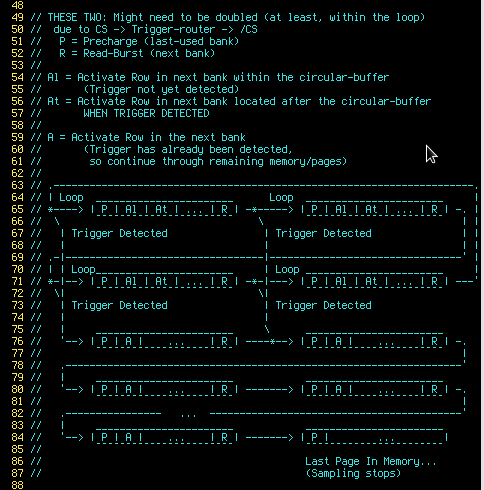
Each "page" in SDRAM is usually 256, 512, or 1024 "columns"... Each column in the Free-Runner contains a command (Precharge, Activate-Looped, Activate-Triggered, Read-Burst, or NOP everywhere else).
So, when a trigger occurs, the current page continues to burst until the next "Activate-Triggered" command, which might actually occur in the *next* page. Whichever page is responsible for the "Activate-Triggered" command will also be completed before the jump outside the circular-buffer occurs. Thus, the trigger could've occurred as far back as nearly 2048 samples before jumping out of the circular-buffer. No biggie, really... There're millions.
Note that it's not possible to have *all* possible "Activate-Triggered" commands jump to the very first memory-page outside the circular-buffer... One can't have two pages open within the same bank. So a read-burst from one bank must always be followed by a read-burst in another bank.
---------
Numerous timing-diagrams drawn for NAND-based systems... switching the active-level of "Triggered", swapping the DQ-latch to the other "branch", switching the active-level of the CS input... and the best I can come up with is to duplicate the AND-OR-INVERT and add yet another inverter at the end. Oy.
I'm sure there's some sort of logical formula that could tell me exactly what to do, but I dunno it... adding an inverter at the end isn't *so* bad, just seems a bit redundant.
Discussions
Become a Hackaday.io Member
Create an account to leave a comment. Already have an account? Log In.