Close
0%
0%

Raspberry Pi heating controller

Domestic boiler regulation without huge
cabling and outlying sensors

Similar projects worth following
System specification
- Domestic boiler (goal, wood) with two hot water loops.
One for boiler constant temperature and second for radiators.
- Raspberry Pi and PiFace interface as control equipment
with some more HW.

MAIN IDEA
To use all building radiators status for regulation without huge
cabling and outlying sensors.
Information of rooms temperature is pick up from temp difference
between input and otput of room radiator. If valve closed than
difference is big and if valve open than difference is small.
It can be used for whole heating system.
If all radiators walve going to close (doas not the metter which
temperature is in a room) then difference between input and output
increase and regulation use lower output temperature. It is working in oposite
situation too. If need more heating than radiator(s) valve going to open
difference is small and regulation increase output temperature.

Heating regulation system include features:

- Starting procedure

- Stop heating

- Shutdown

- Overheating (emergency)

- UPS cooperation for emergency stop

- WiFi LAN connection for remote command line

There will be Stage two to use practical experience from system application

.

STAGE 2 on the way - Web interface and MySQL is working!

Stage Two include:

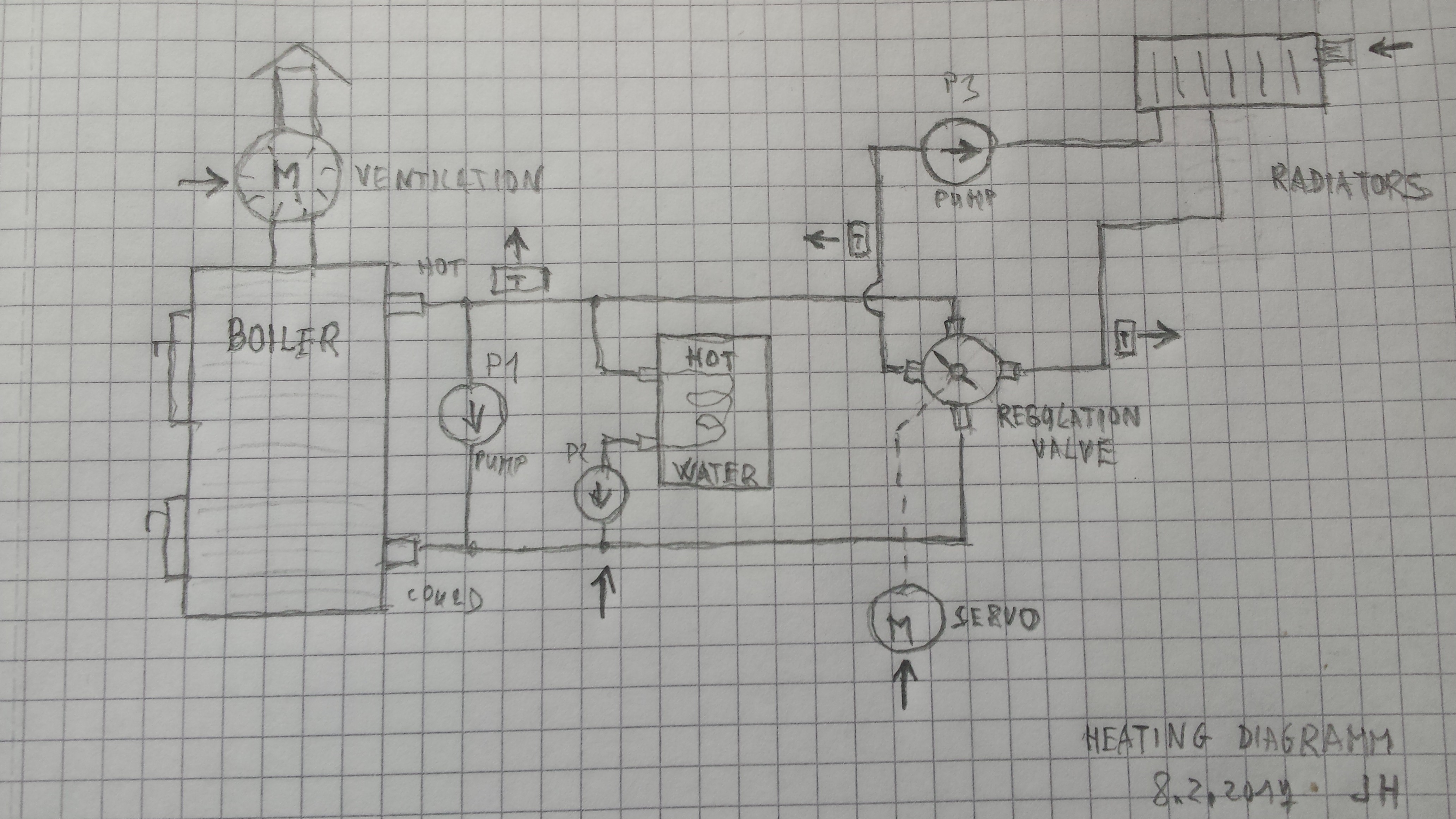
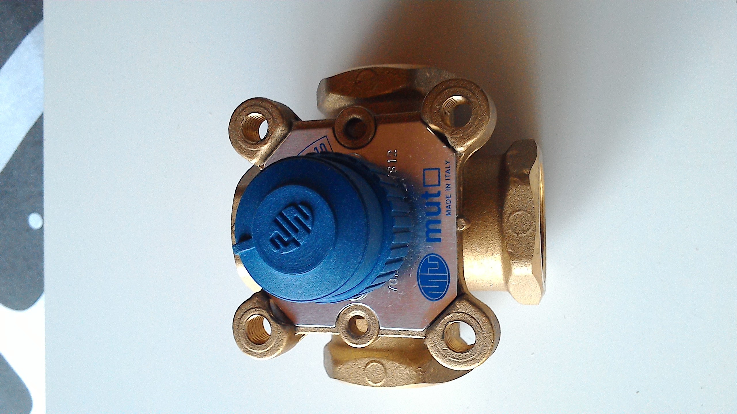
- Change regulation valve from threeway to fourway

- Remote Low boiler temperature alarm

- MySQL for statistic and settings

- Web interface

Stage two required main change of Pi SW becouse regulation valve change. Current first boiler loop with thermostatic element (like car cooling thermostat) end threeway valve for radiators loop will be change for fourway valve only. Reason for the change is that thermostat is non linear element which make regulation loop unstable and complicate SW regulation.

Now I am waiting for end of heating season and changes should be ended untill November 2016 as deadline.

Code is writen in Perl. Could be possible to use any Raspberry Pi model.

.

Second (Main Idea)

Regulation valve servo use analog input from 2 V to 10 V. I am lazy to work with 10 bits outputs from D18B20 and D/A converter. It is why I used four bits outputs from PiFace interface as:

Down

Fast Down

Up

Fast UP

(No change)

There is long time RC constant and PiFace outputs changes guide charge or discharge of one big capacitor. Capacitor voltage is output for the servo.

Other outputs:

- First water loop pumpe switch

- Second loop pumpe switch

- Flue exauster switch (regulate boiler itself temperature)

- Red LED for not in operation mode.
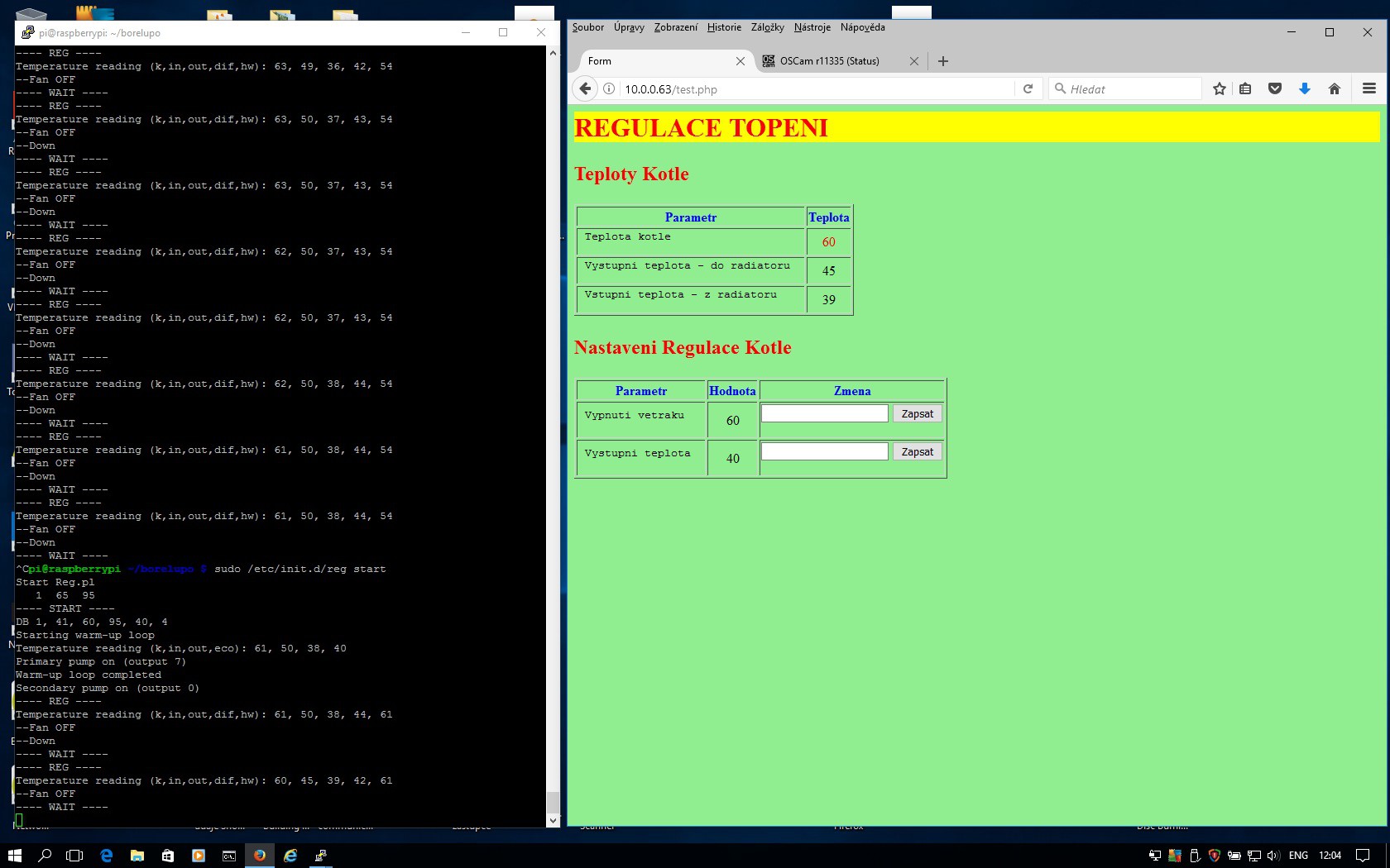
STAGE THREE IDEAS

  • New web page with boiler status and informations from various sensors. (Current web page is mainly for system check and developing.)
  • Connect controller to ZigBee network to collect other sensors data.
  • Try to predict from boiler data time to boiler refuel necessity?
  • ZigBee boiler status indicator. (Green, Yelow, Red, sound alarm)
  • Use D/A converter instead analog stuff.

WEB interface.jpg

WEB interface live now.

JPEG Image - 134.17 kB - 06/06/2016 at 07:54

Preview
Download

Heating_HW.jpg

Raspberry Pi, PiFace interface and REG hw

JPEG Image - 805.35 kB - 04/11/2016 at 07:44

Preview
Download

Heating_ps.jpg

Diagram of power supply. Main 12V power supply is in mains boiler distribution box.

JPEG Image - 1.37 MB - 04/11/2016 at 07:39

Preview
Download

heating diagram.jpg

Schematic diagram of analog regulation connected to PiFace interface, valve servo and power supply.

JPEG Image - 2.65 MB - 04/05/2016 at 12:36

Preview
Download

  • Next will be?

    JanoHak03/07/2017 at 09:01 0 comments

    I finalize all main targets of the project.

    But I have a lot of experince for next generation. (Heating NG) :-)

    Heating NG

    I would like to make radical simplification:

    To Remove:

    - Analog staff

    - Relays (relays shoud be at switchboard)

    - PiFace interface

    To Add:

    - A/D converter for analog servo

    - Simple Interface for switchboard relays.

    - Alarm interface

  • SW changes made

    JanoHak03/07/2017 at 08:38 0 comments

    Regulation is working as I would like. Remain small problem is could start optimalization. System is starting longer time than possible speed for rooms warm up.

    Finally I used regulation with main heating temperature setup with big corrections depend on in/out radiators temperature difference which is slightly different from initial idea. Reason is system stability and more easy full power mode.

    I add servo (regulation) speed possibilities Up, FastUp, VeryFastUp as wel as Down, Fast Down in programm to make change speed progressive. Other problem solved is temperature time response of boiler and radiators. Regulation must work in same time range. It is important for regulation loop stability.

    It is working fine now. Only remain things are to add to web interface heating current temperature setup (with correction) and could start up improvement.

    Becouse not typical heating use (weekend heating only) I still working on remote ESP8266 thermometer to measure some room to know if minimum temperature to reach. Untill minimum temperature reached, heating should work in full power mode without regulation and hot water warming. It is important for quick room temperature restore after some day without heating.

  • Optimalization

    JanoHak02/08/2017 at 12:31 0 comments

    I still continue to optimize sw for best performance and stability. Web informations are more simple. I get out garbage parameters used for system development. I would like to use wireless temperature ESP8266 sensors to publish it on the web as well as wether informations or some home automation usefull thinks. Important question is how to predict refueling needed as alarm. Low boiler temperature is too late signal. Maybe chimney ventilation regulation make me happy :-)

    Picture contains simple web and serial output from Raspberry with restart.

  • Final pipe configuration

    JanoHak02/08/2017 at 11:51 0 comments

    After three changes of pipes or components configuration I finalize it. Main diference against mainly used config is P1 pump in paralel with boiler. It is best fot stable boiler temperature and more linear regulation characteristic of four way regulation valve. It is much more better than pumpe with thermostat (recomended by producer) or cammonly used pumpe on fourway valve low temperature intake to boiler.

    A bit surprise was unsymetric system reaction for regulation attempt. Temperature up is quick but go down with output temperature take a time because hot water is mixing with relative hot radiators back water and result is small and slow change.

  • Valve regulation work OK now

    JanoHak11/14/2016 at 09:18 0 comments

    After second evolution of four way valve reconstruction scheme it meet my expectations. Fluently regulate throw whole valve handler angle range.

    It is fanny but most pipe diagramm on public internet are wrong. It is working but far away from optimal.

    For example like this:

    Because pump at could way to boiler. (čerpadlo kotle)

    Much more better is to make separate circuit "boiler - pump - boiler" which make boiler output and input on similar temperature. What is best for boiler performance. Four way valve "input" is in parallel to boiler and building side is connected to "output" side of fourway include second pump. If somebody interested I can draw some picture of it.

    Hot water boiler is simply in paralel to main boiler without any additional equipment. Have to be in the middle between hot and could pipe of the main boiler, means altitude. (in my case it is)

    Now I can start with regulation SW! Hu Hu

  • Good news (for change)

    JanoHak11/09/2016 at 19:48 0 comments

    It is a bit out of scope of this project but it pleased me a lot!

    Boiller should warm hot water for bathroom too. Usuallly there is third pump what sent hot water to warm up extra boiller for it. I am starting to develop sw procedure to start/stop the third pumpe.

    But if hot water boiller is connected to main boiler and placed between up and down lead (pipe) than it is working fully automatic without any valve or electronic. Great, I did not see somethink like this!

    Principle is fany. Hot water from backward pipe what going to main boiler climbing up oposite way and replacing cold water inside hot water boiler spiral pipe. (gravity circulation)

    There should be manual valve to regulate power volume. Could hot water boiller is able to assume whole main boiler power! It is why there should be throttle valve to slow down heating. This sytem continously keeps hot water boiler full of hot water.

    Incredible !

  • Four way regulation problem

    JanoHak11/09/2016 at 18:55 0 comments

    I am terribly out of project schedule. New boiller regulation valve not meet expectations on tests. Basically it is working and it is usably but looks strange.

    Whole regulation range is round zero valve adjustment and it is very sensitive for boiller (first) pump power. Something what looks clear and flat become more complex. ( As usually... )

    Looks like nobody knows how it is working include me! Hydrodynamic as well as aerodynamic rools are out of human senses. On internet and at pratice what a saw regulation configuration all the same. Two pumps and four way valve between. It is what I built up now. Of course there is stupid idea too tu use one pump only. It leave boiler in bad environment and health conditions - low end boiller is at very low temperature.

    I have to go my own way to do it. This weekend I will start from zero and will rebuilt pipes and valves again! Second problem to solve are shame air bubles in system because I did not take care about it and wrong air release valve to replace.

  • Boiler "HW" upgrade

    JanoHak08/02/2016 at 08:32 0 comments

    Old boiler regulation debris...

  • Boiler regulation upgrade

    JanoHak07/11/2016 at 16:44 0 comments

    New fourway valve.

  • Stage three ideas

    JanoHak06/30/2016 at 08:54 0 comments

    • New web page with boiler status and informations from various sensors. (Current web page is mainly for system check and developing.)
    • Connect controller to ZigBee network to collect other sensors data.
    • Try to predict from boiler data time to boiler refuel necessity?
    • ZigBee boiler status indicator. (Green, Yelow, Red, sound alarm)

View all 16 project logs

Enjoy this project?

Share

Discussions

Similar Projects

Does this project spark your interest?

Become a member to follow this project and never miss any updates