 [skaarj]
This was done at the beginning, but until now I had no chance to write a log about this.
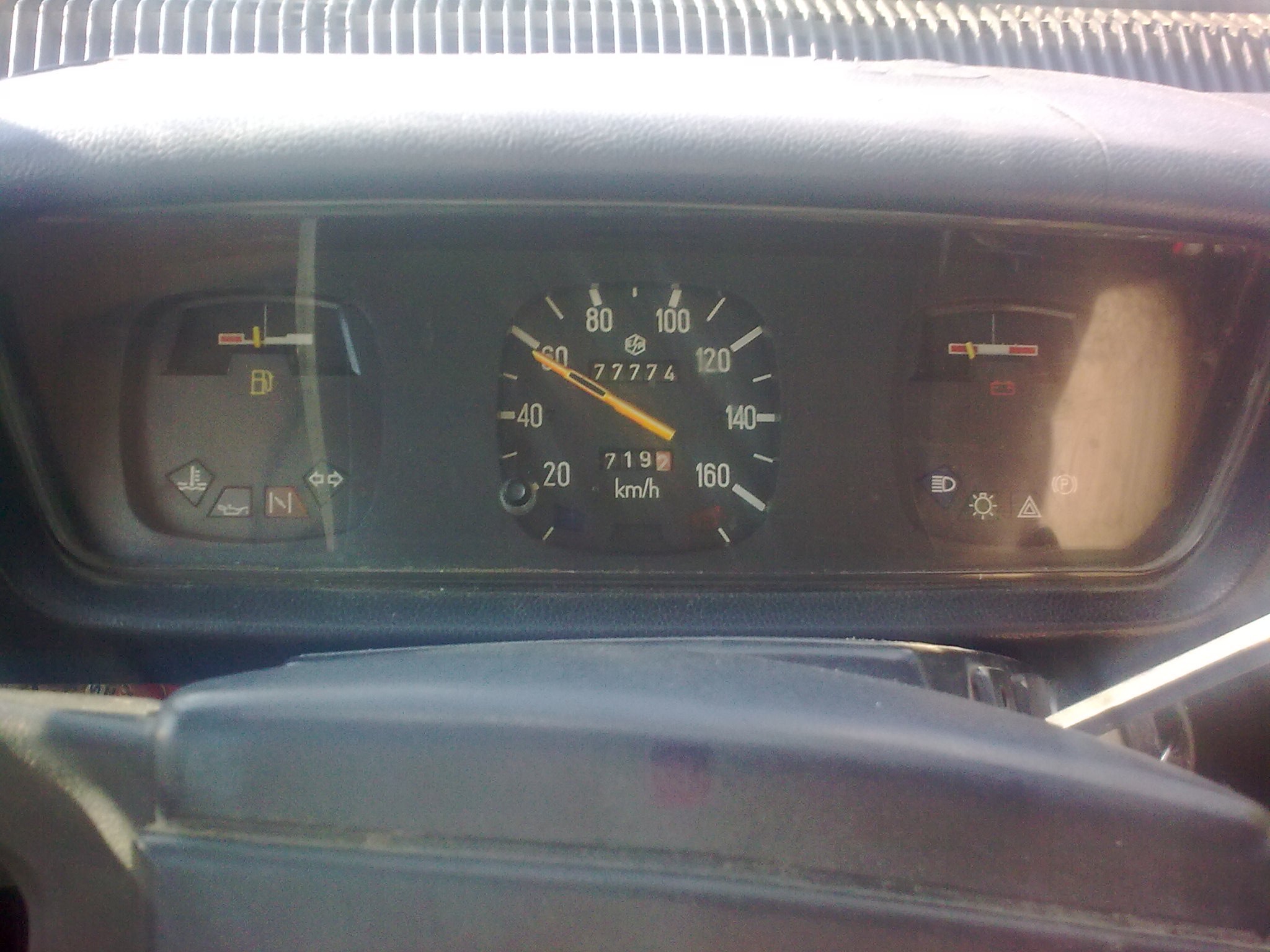
So why do I want to mess with the dials? Simple, because the original dials look sad. They show nothing I can use to understand about the engine.
The desired functions are as following:
- back light for the gauge pointers (needles);
- back light for the gauge dials;
- each light is adjusted independently;
- two extra gauges added;
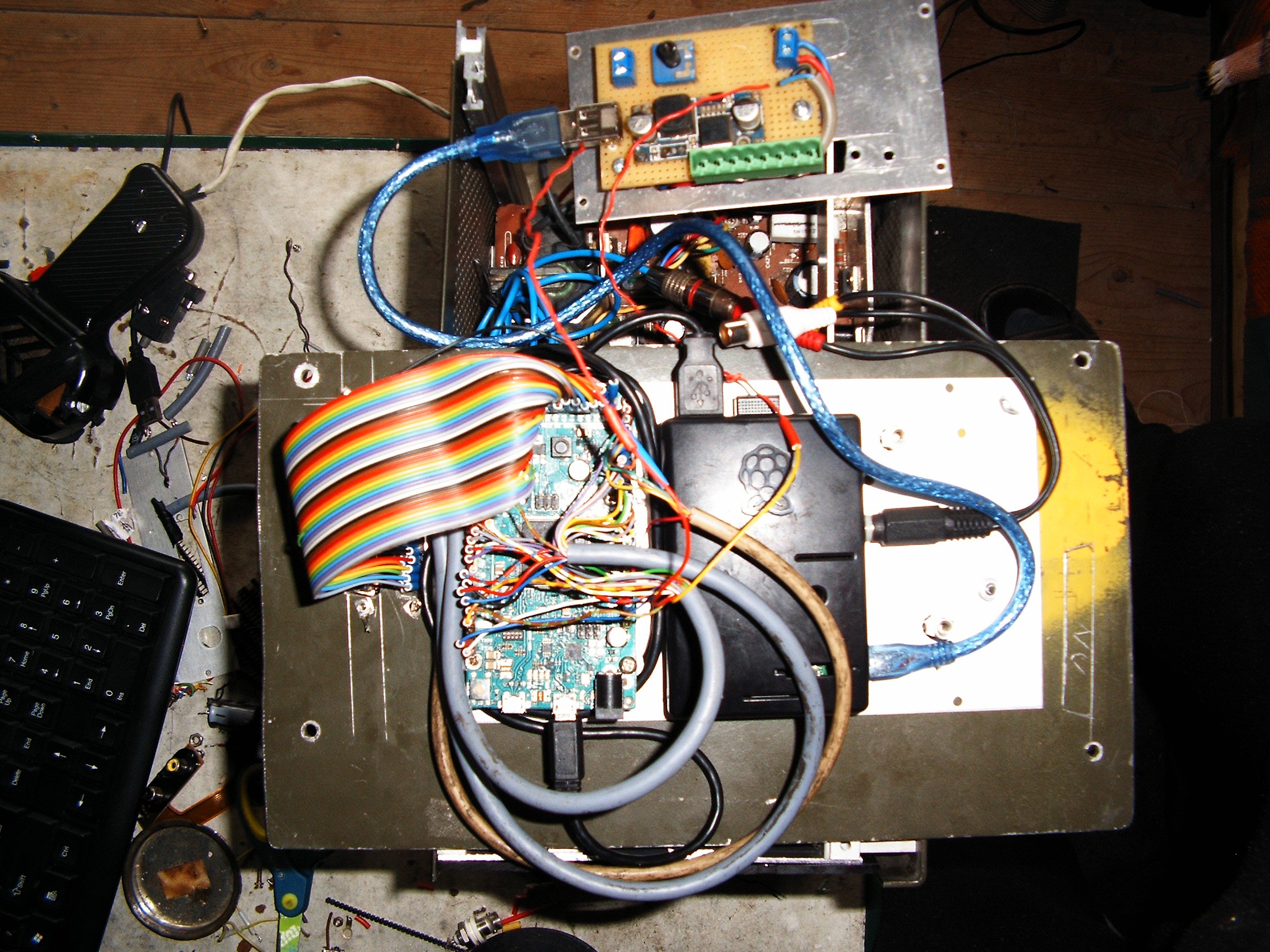
- all gauges (except speed and RPM) are controlled from the Arduino;
- light (leds) and gauges are controlled through two Adafruit PWM controllers;
- Arduino encodes all these parameters according to the protocol I designed and built - based on some Petroleum Industry Data Transfer Standard called WITS - and sends them to the Raspberry Pi embedded inside the terminal.
So let's start:
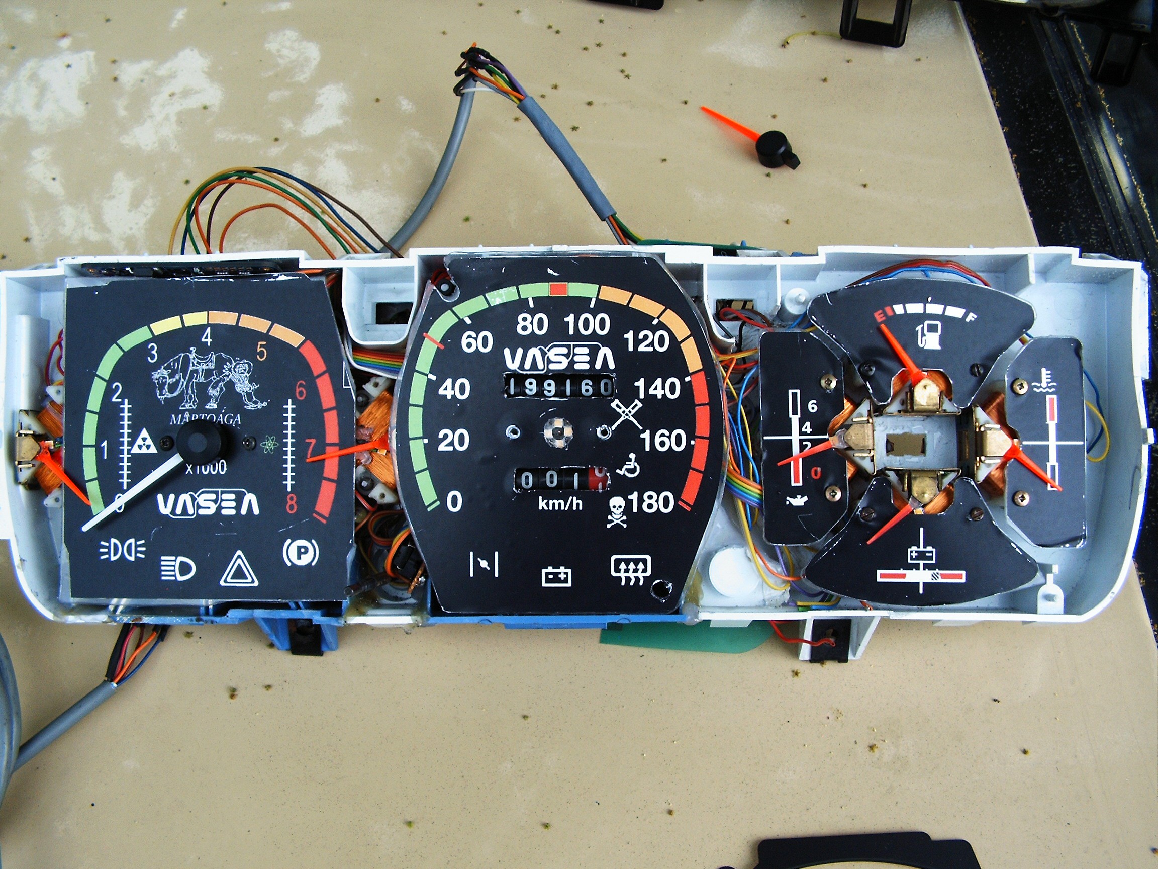
GAUGES!!! a lot of gauges!
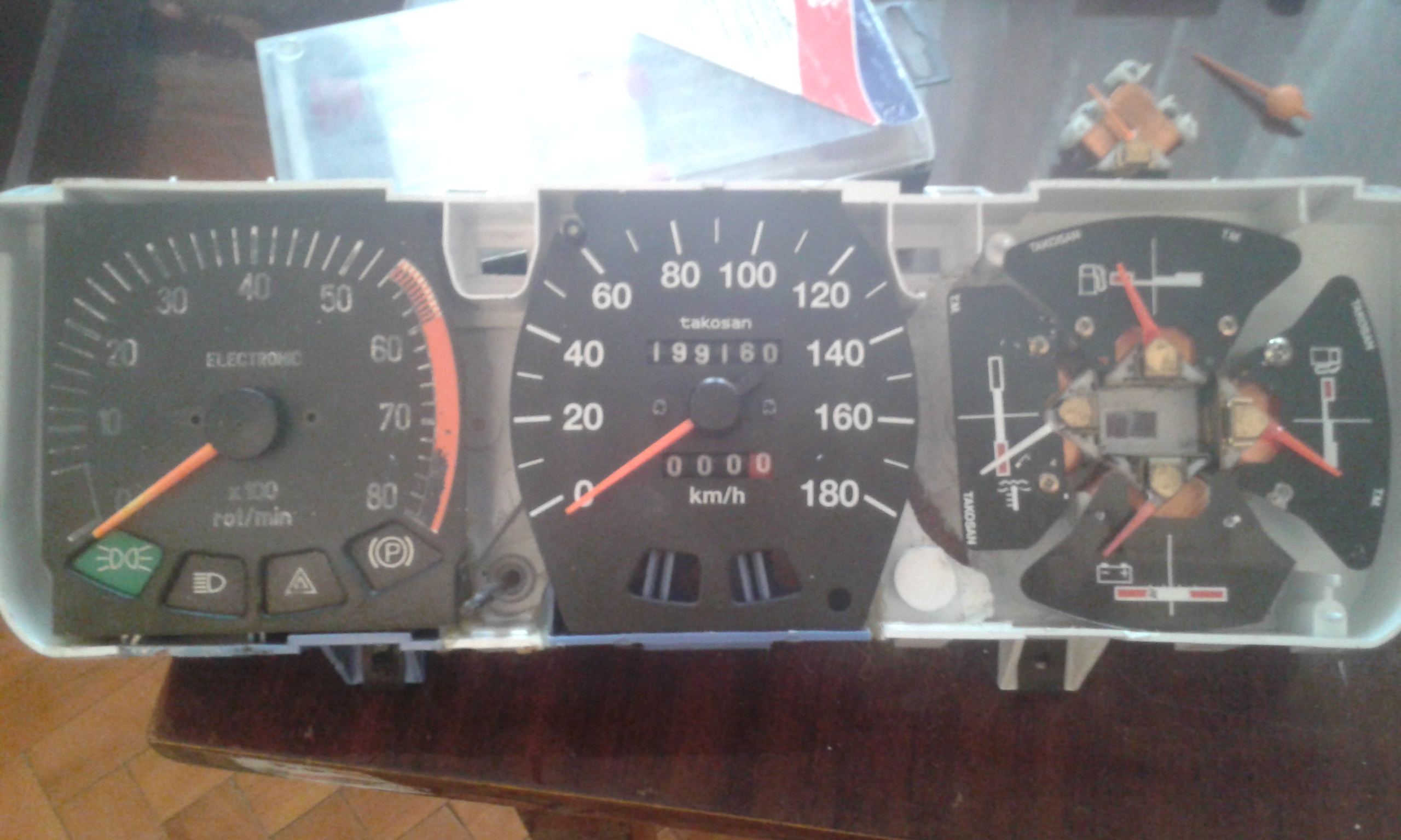
 Left side: the old version casing with more warning lights than the newer version. Last version had only two gauges - gasoline and speed. I need the precision of the last version dials but I want to know as much information as possible about the engine.
Also, the last version speed gauge has a different "daily distance reset" which does not fit on the old casing. So switching to new casing and adapting the best methods.
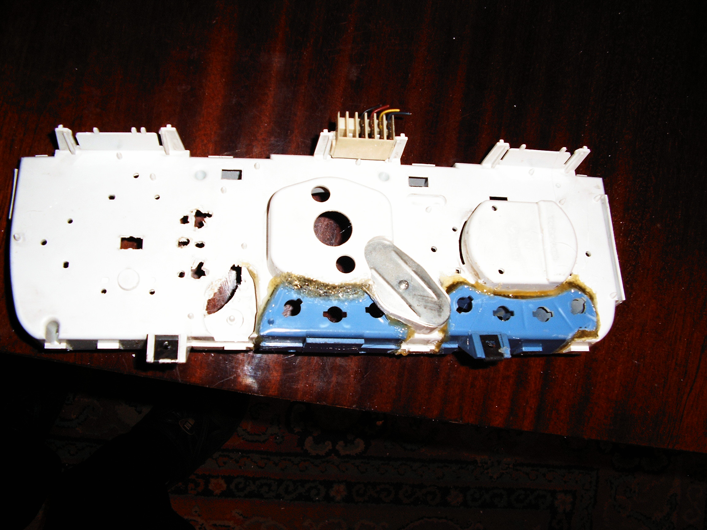
So I have to cut the warning lights enclosures and stick them on the newer version casing.
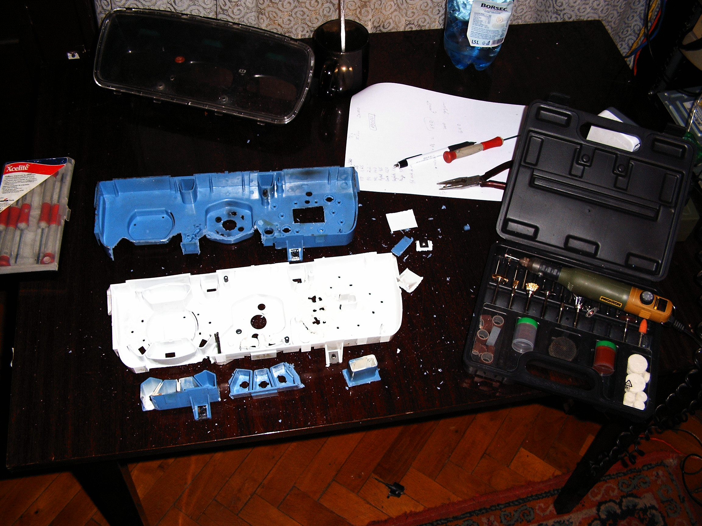
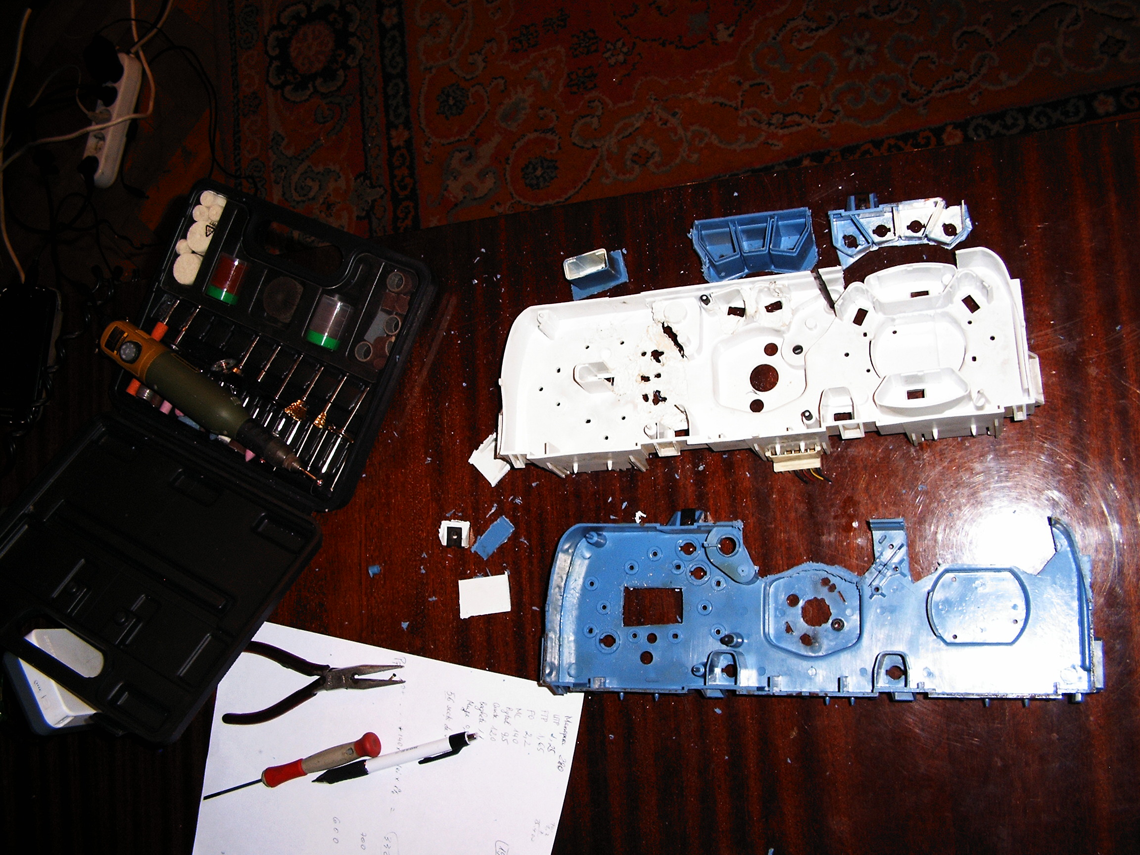
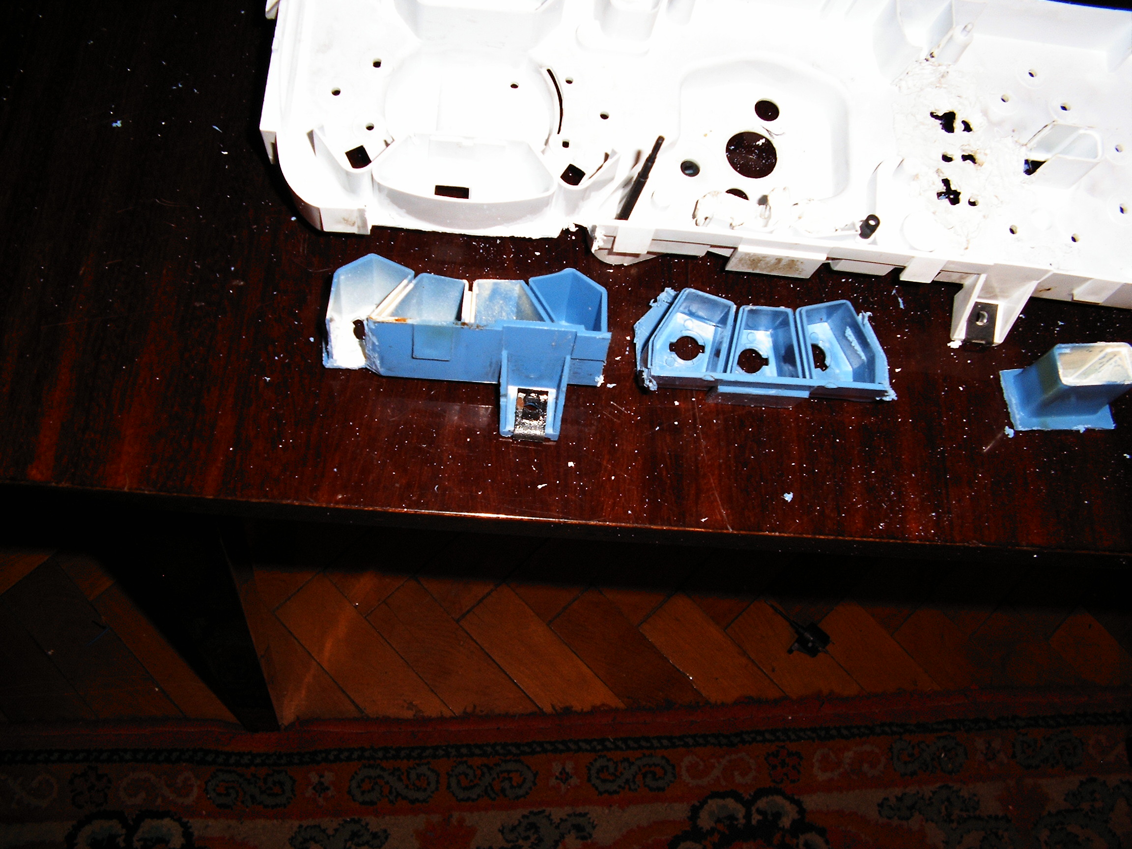
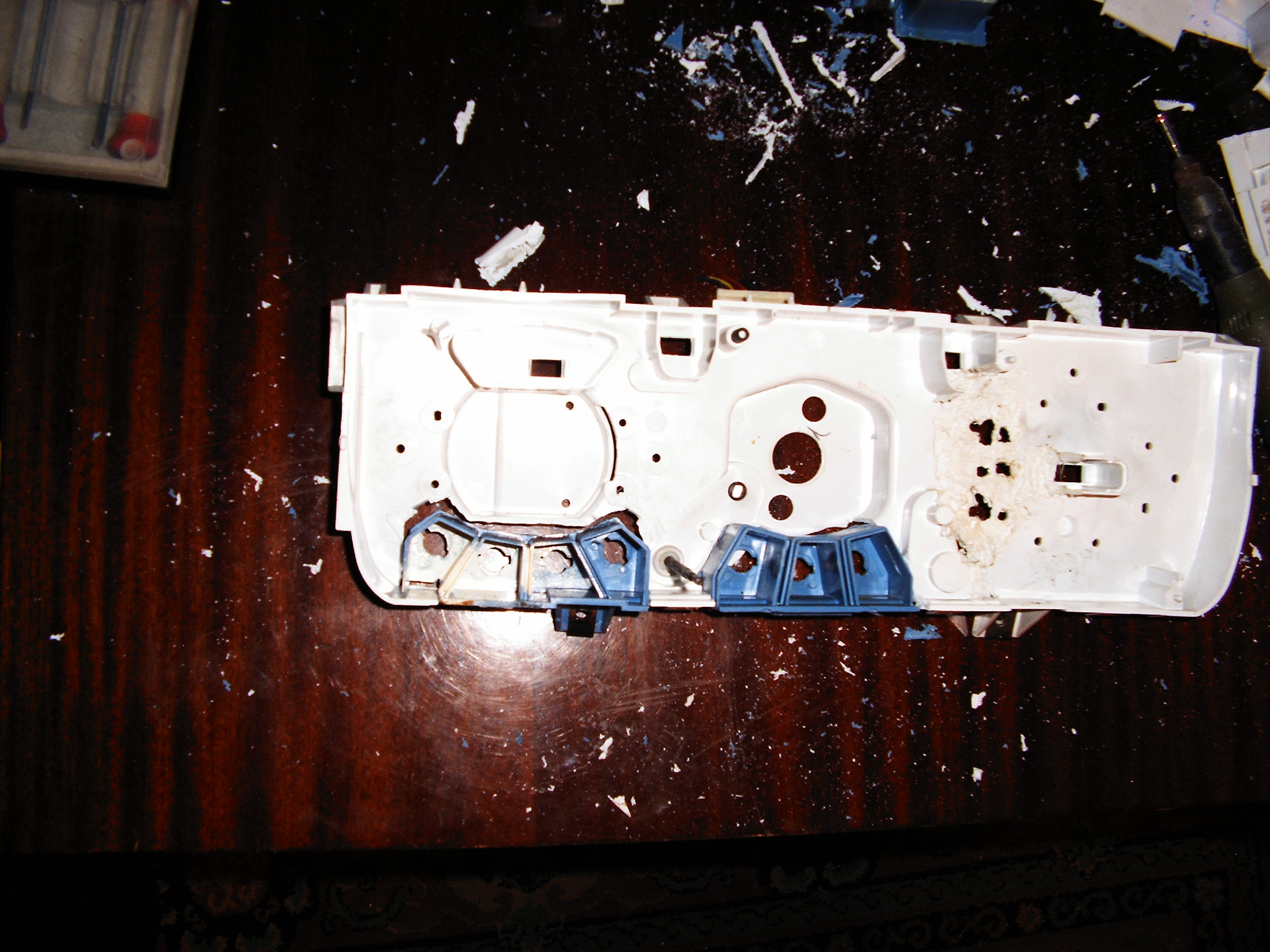
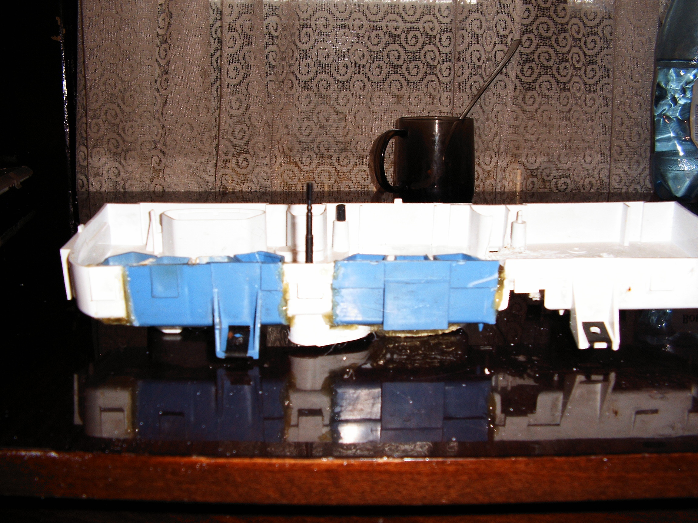
Finally they are cut together, now let's "fuse" them using melted plastic:
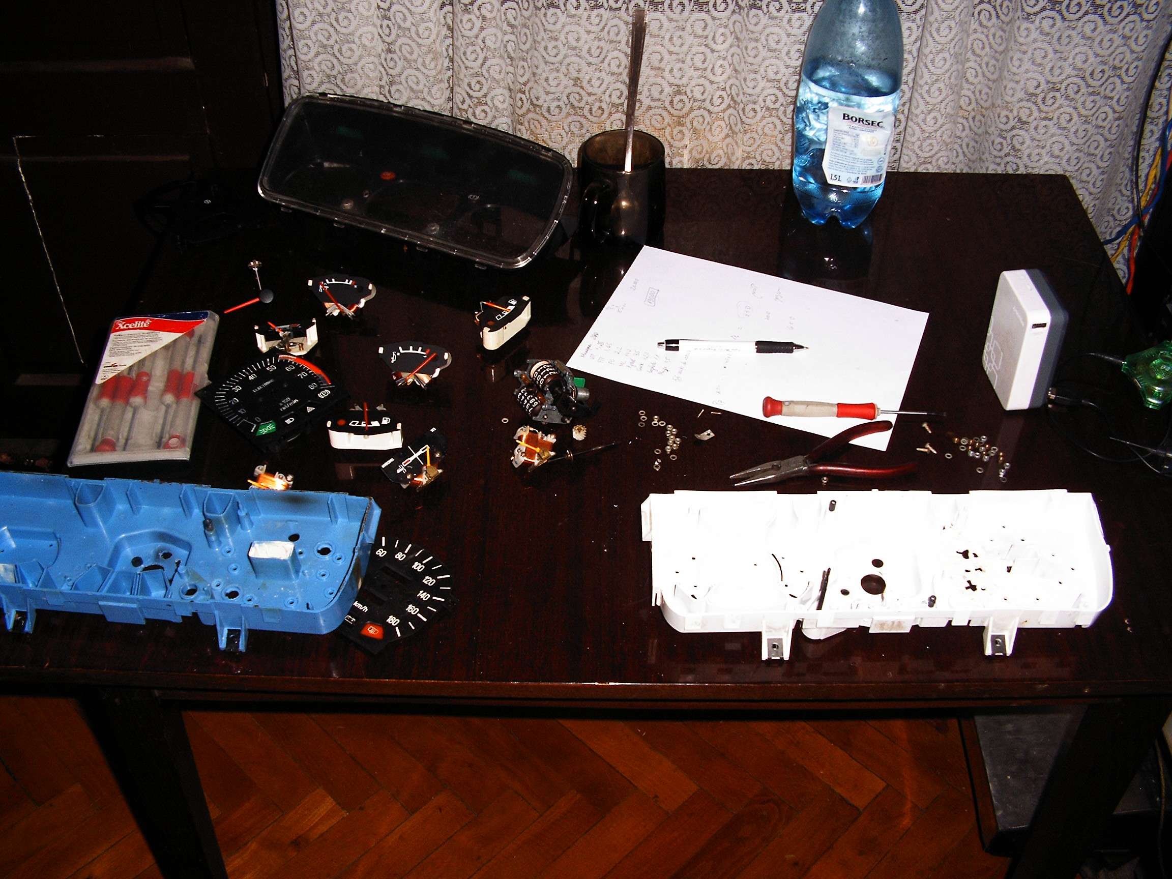
Dials pointers.
Camera has focusing problems.....
Transparent plastic needles recovered from some vehicle recycling center.
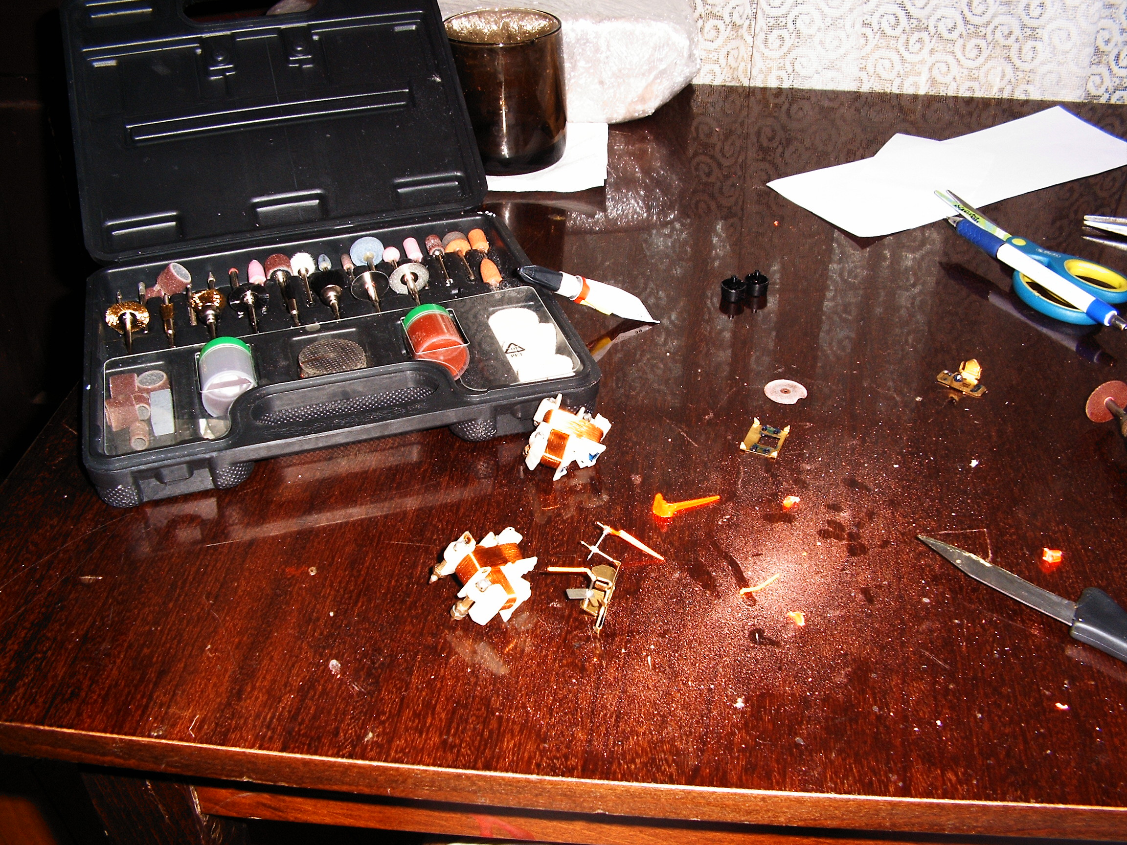 The aluminum pointers were removed and the new pointers were fixed using Super Glue and a lot of patience. Adjusting weights for was done for each of the 6 small gauges.
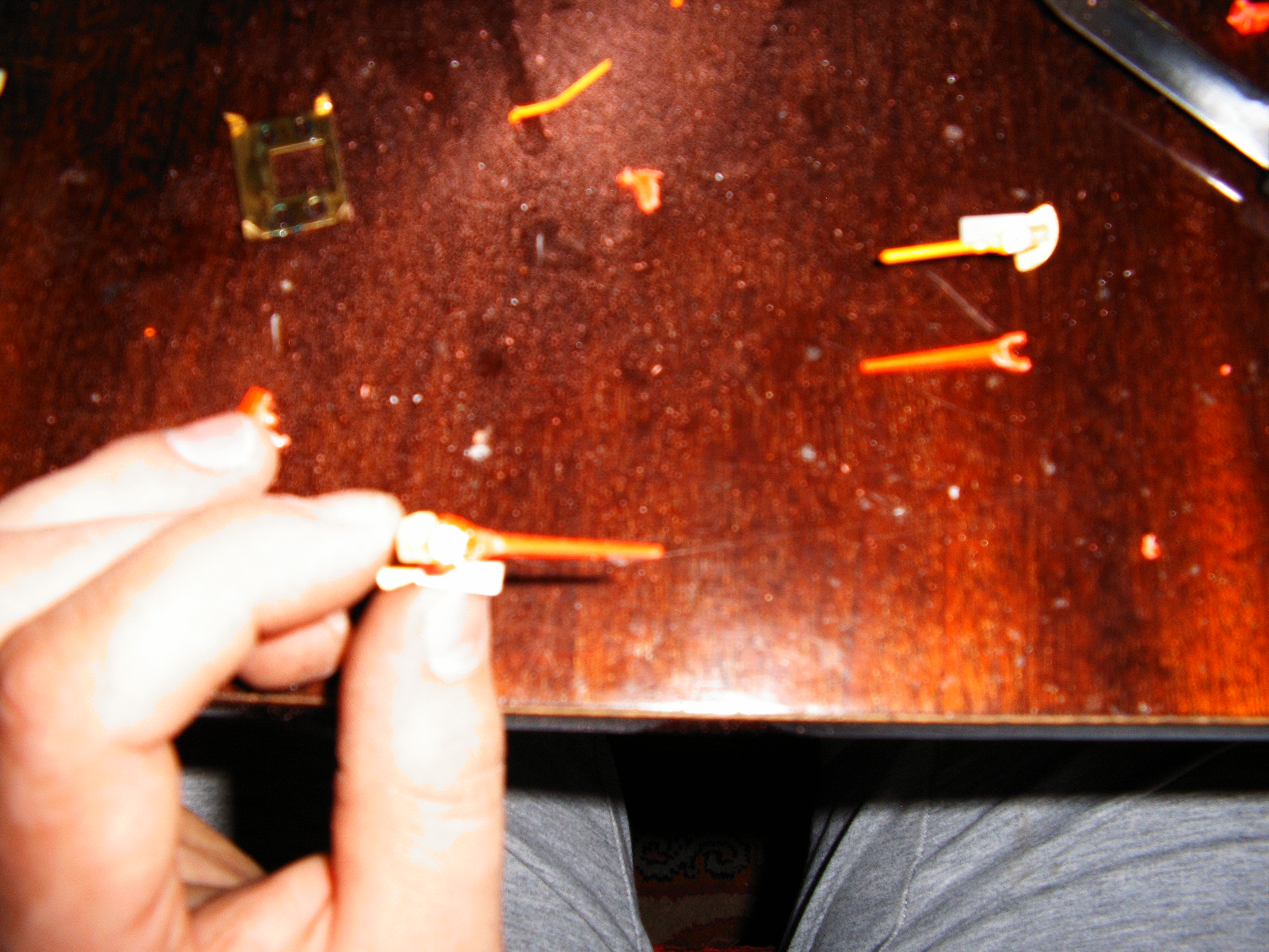
 Adjusting the balance was performed with the dremel tool by cuting small pieces of plastic from the pointer.
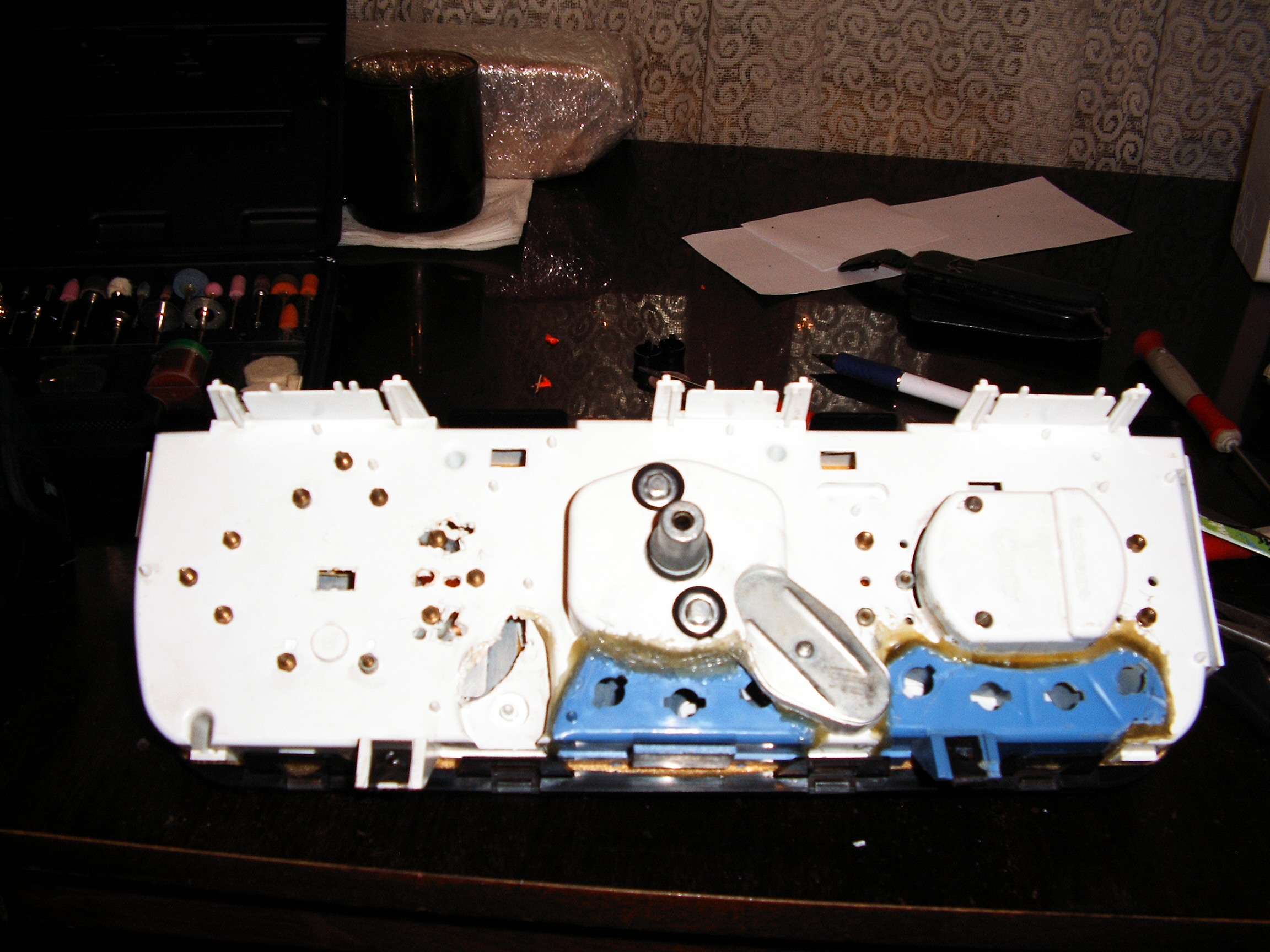
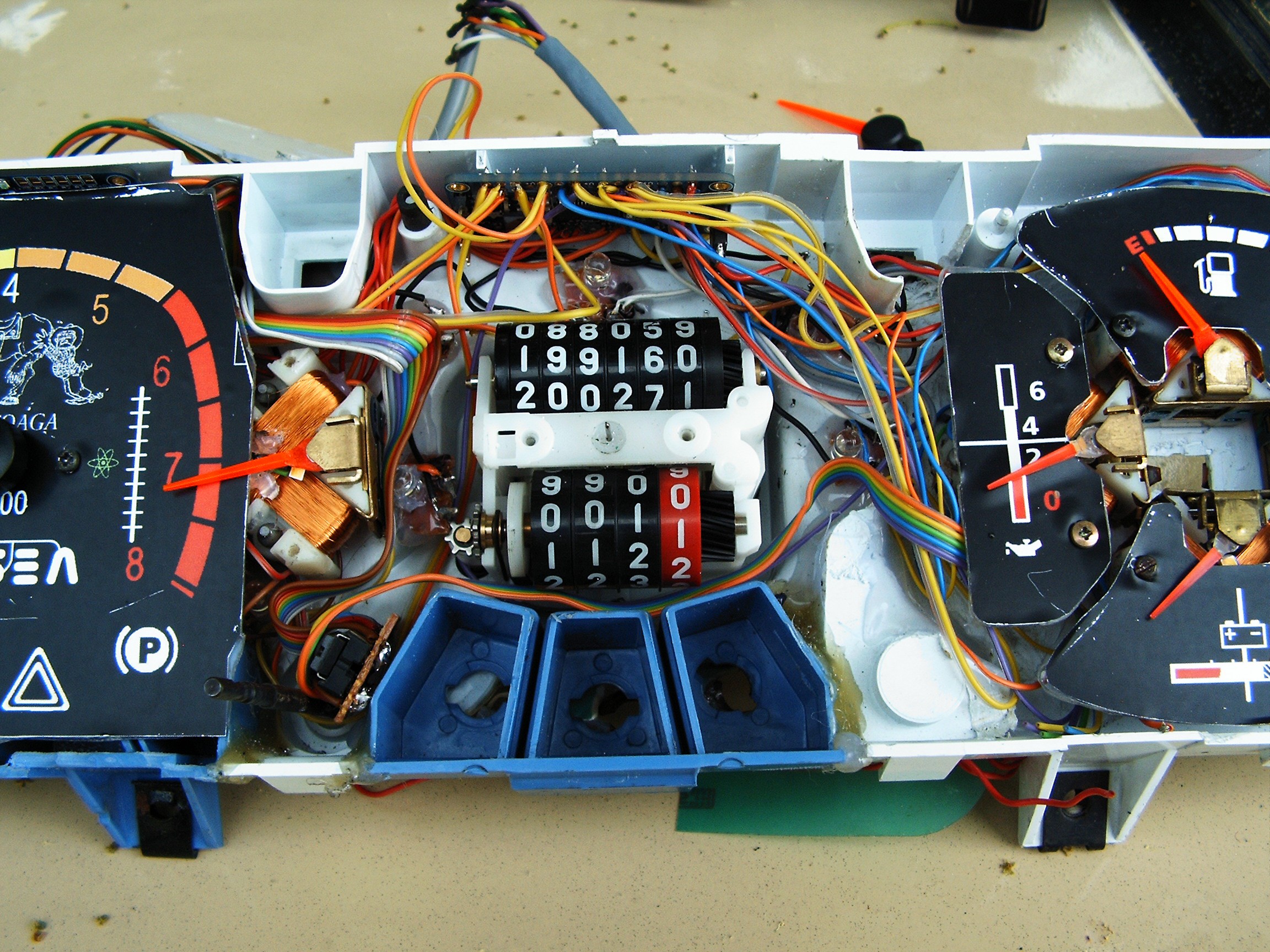
Installed instruments - back side view
This is how it should look like - this is a gauge modification I made for my motorcycle:
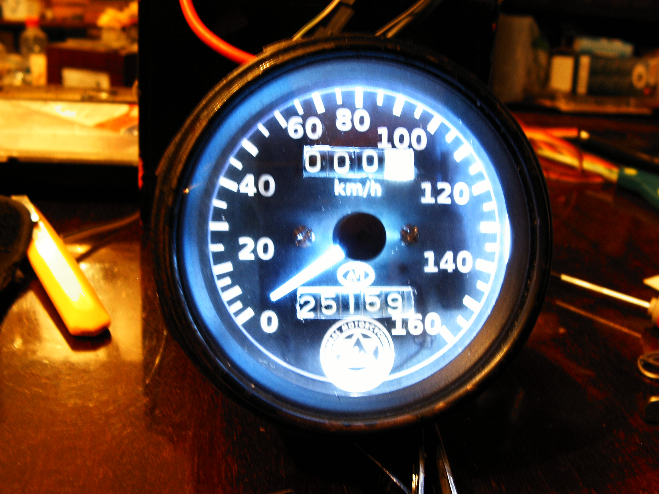
Dash board with new dials.
It is impossible to view the blue drawings during day time, so changes are expected for dial colors.
On the RPM meter ( left side) there are the two additional gauges. Still not sure what to display with them, but they look nice. Probably radiation level and battery charging current.
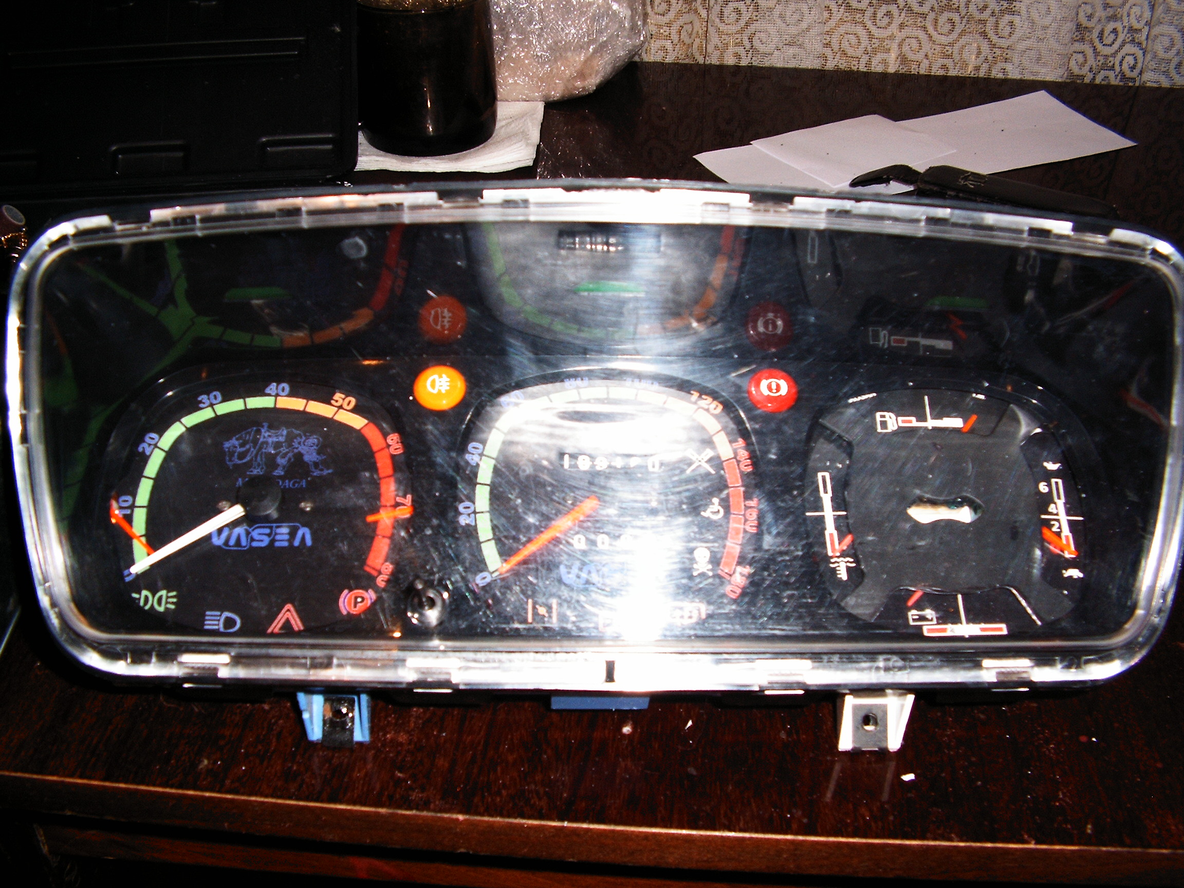
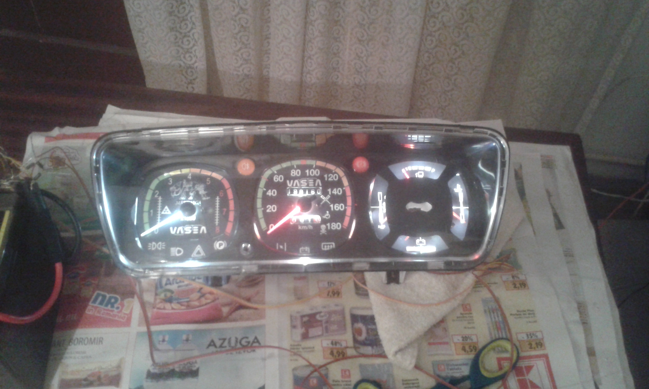
The picture below shows the other dash I keep in the car while upgrading the one above. So it's a second dash. 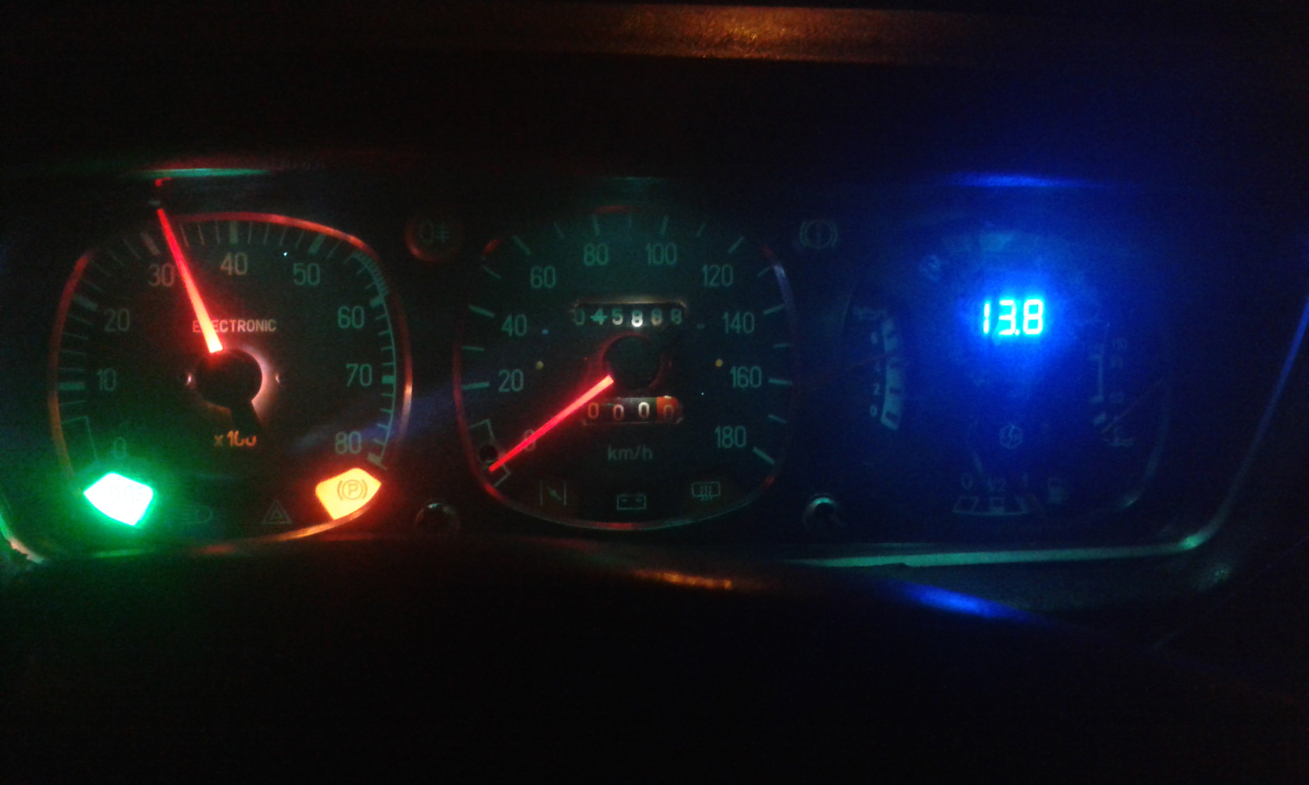 And It looks better in reality.
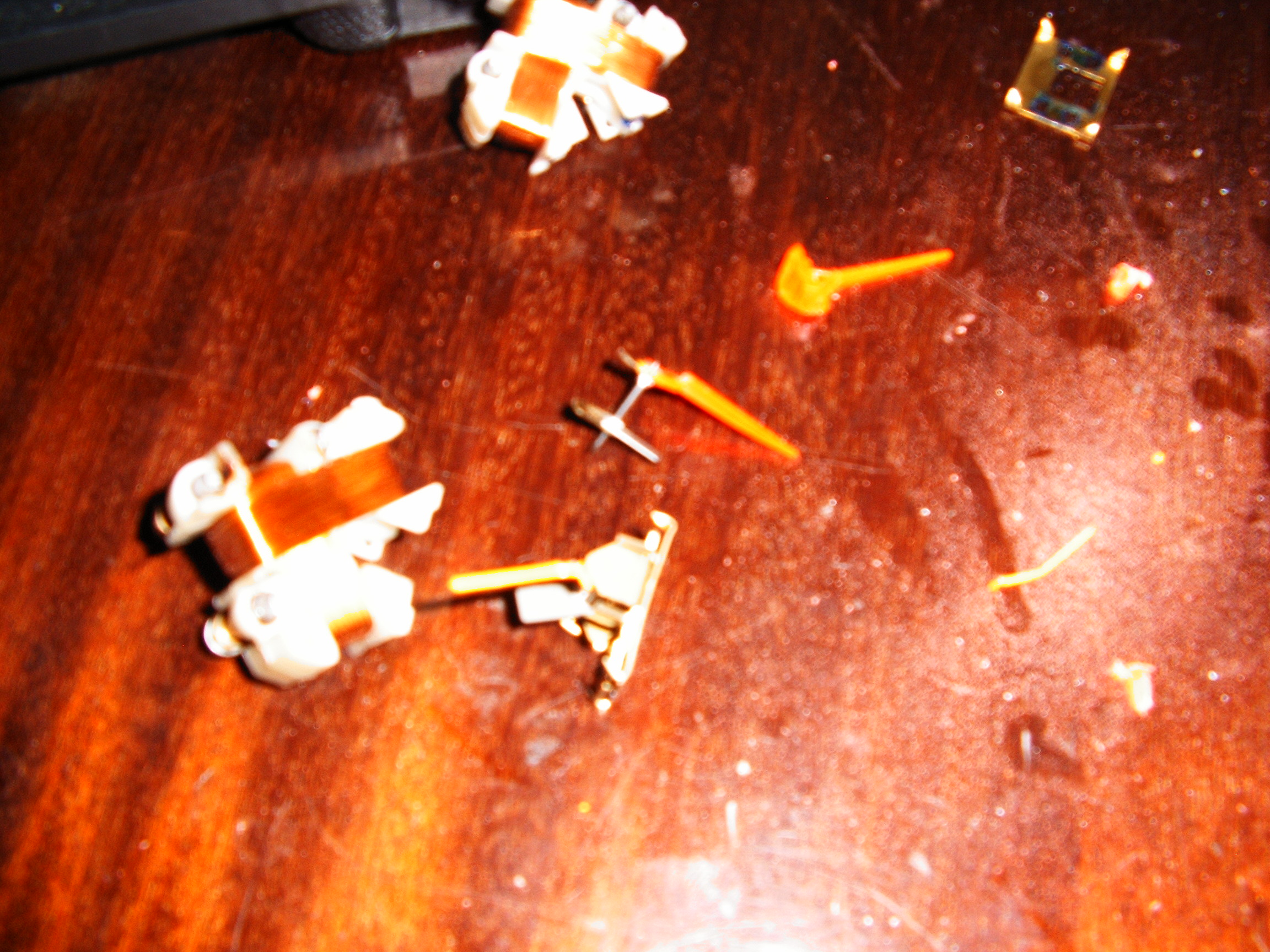
So an old dash (latest version) had only one speed gauge and one small gasoline gauge. I need 6 smaller gauges, so I had to dismantle the dashes from 6 other cars...
This is how it looks during day time.
 This is without background LED controls.
The ready to print dials are stored in the Files section.
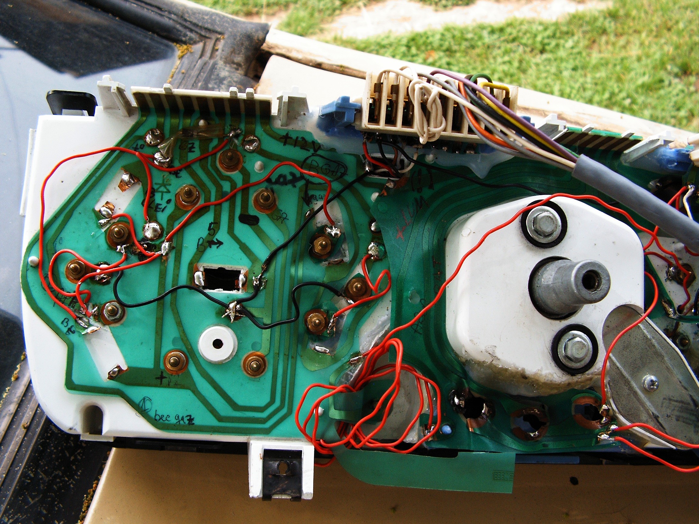
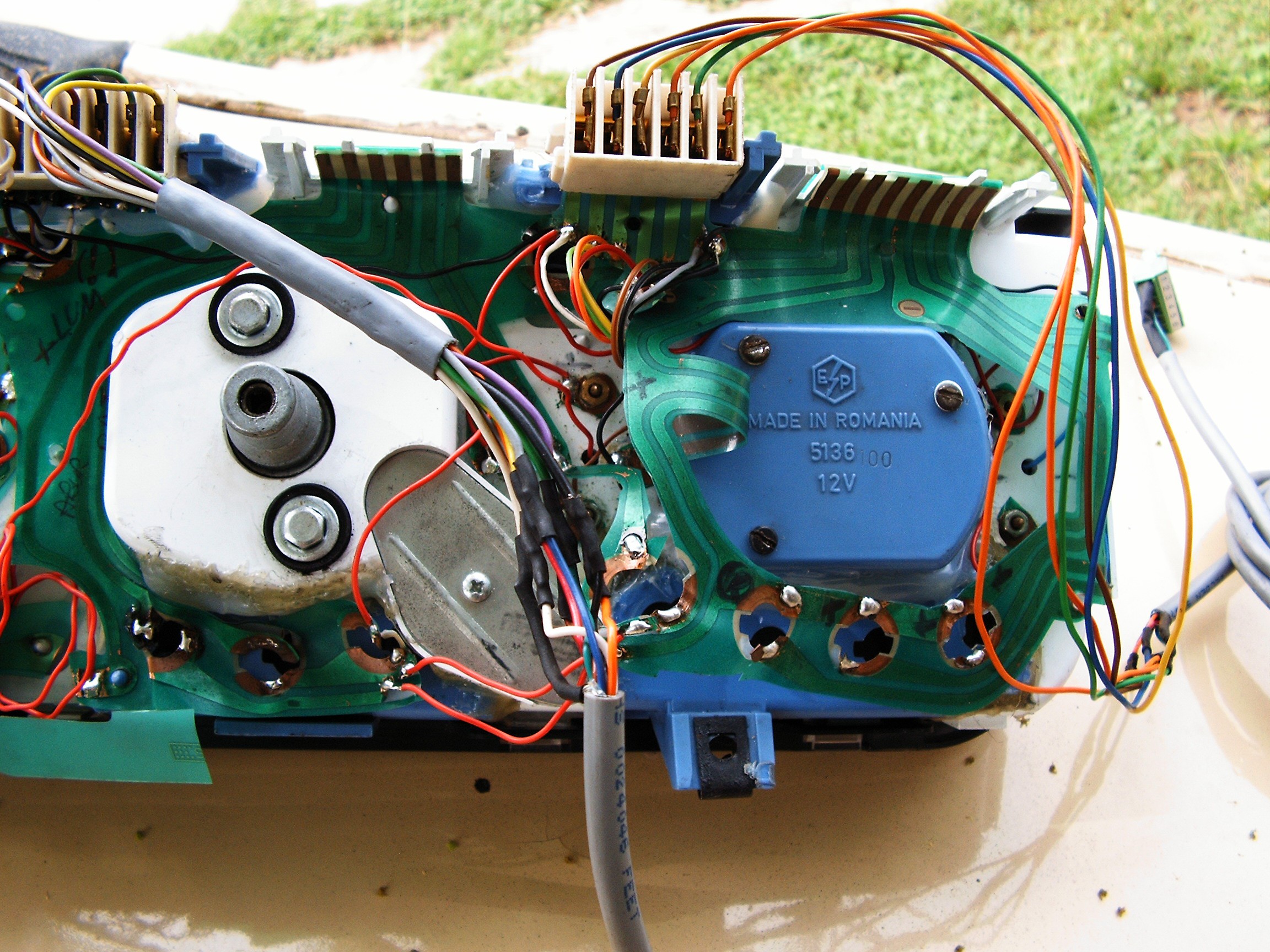
Somehow I missed the pictures and schematics for the back-side electric connections.
Later edit: traffic jams are unforgivable, I hope I will upload missing pics and schematics in time.
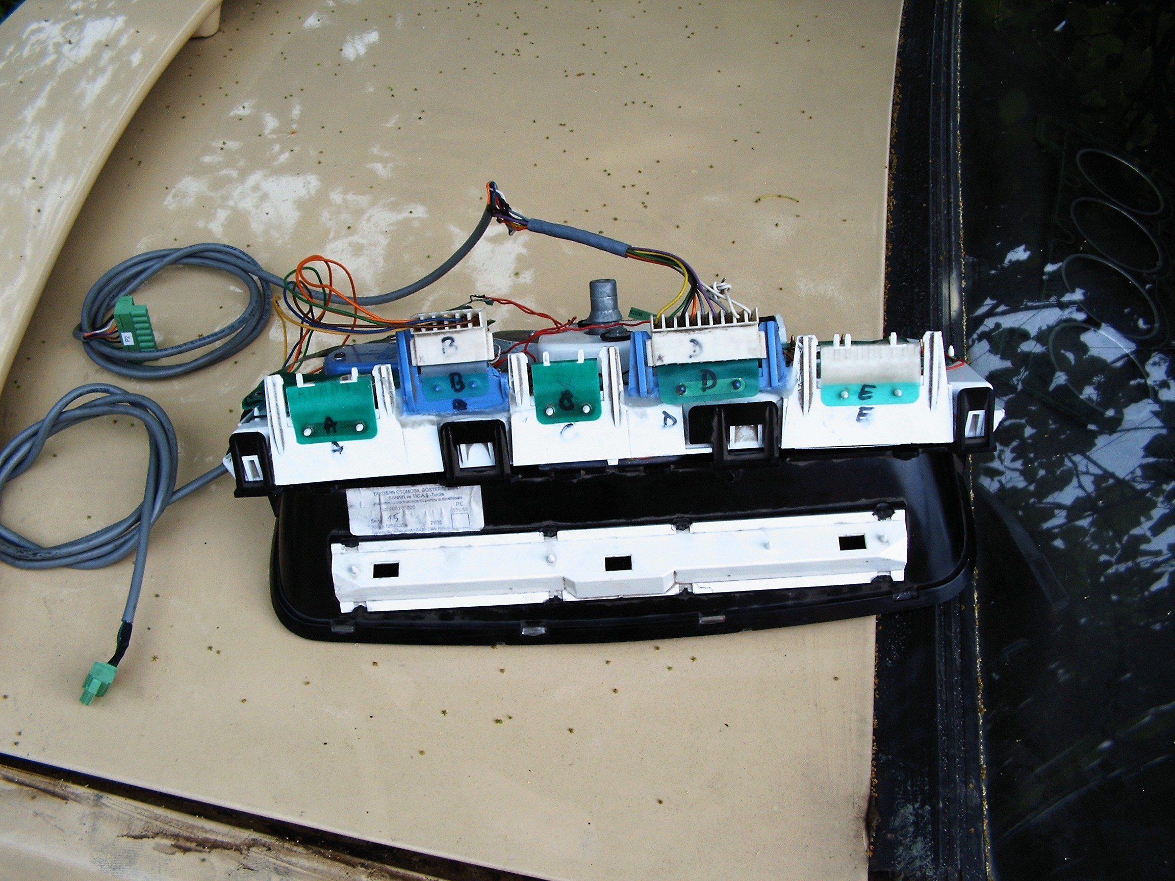
The A, C and E connectors are the originals one.
Added connector B (gauge PWM control) and D connector (Led PWM control).
Schematic - hand drawn as usual:
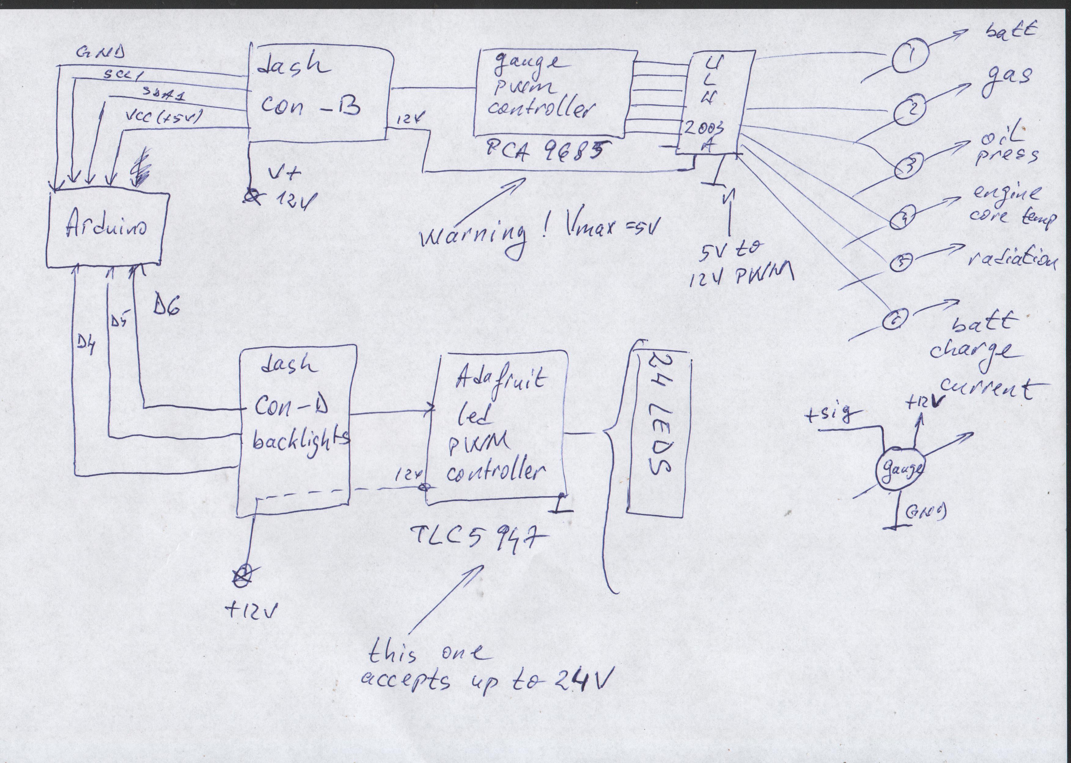
The Arduino Due above will also send the lights and gauges parameters using my own designed Can Bus Protocol to the Raspberry Pi II embedded in the terminal.
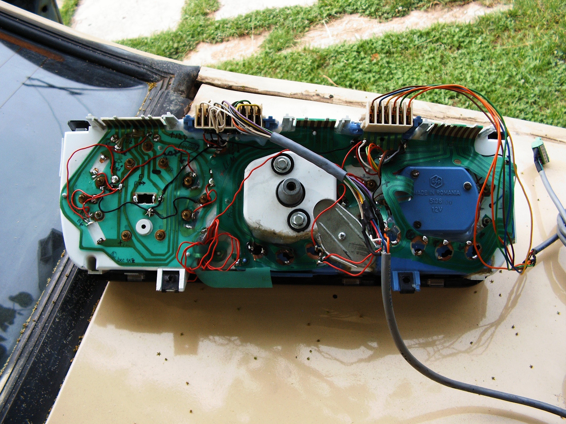 Somehow I managed to modify the back flexible PCB according to the schematic above.
There are some holes in the bottom side, middle and right. Some 12Volts LEDs will be installed there, awaiting package to arrive.
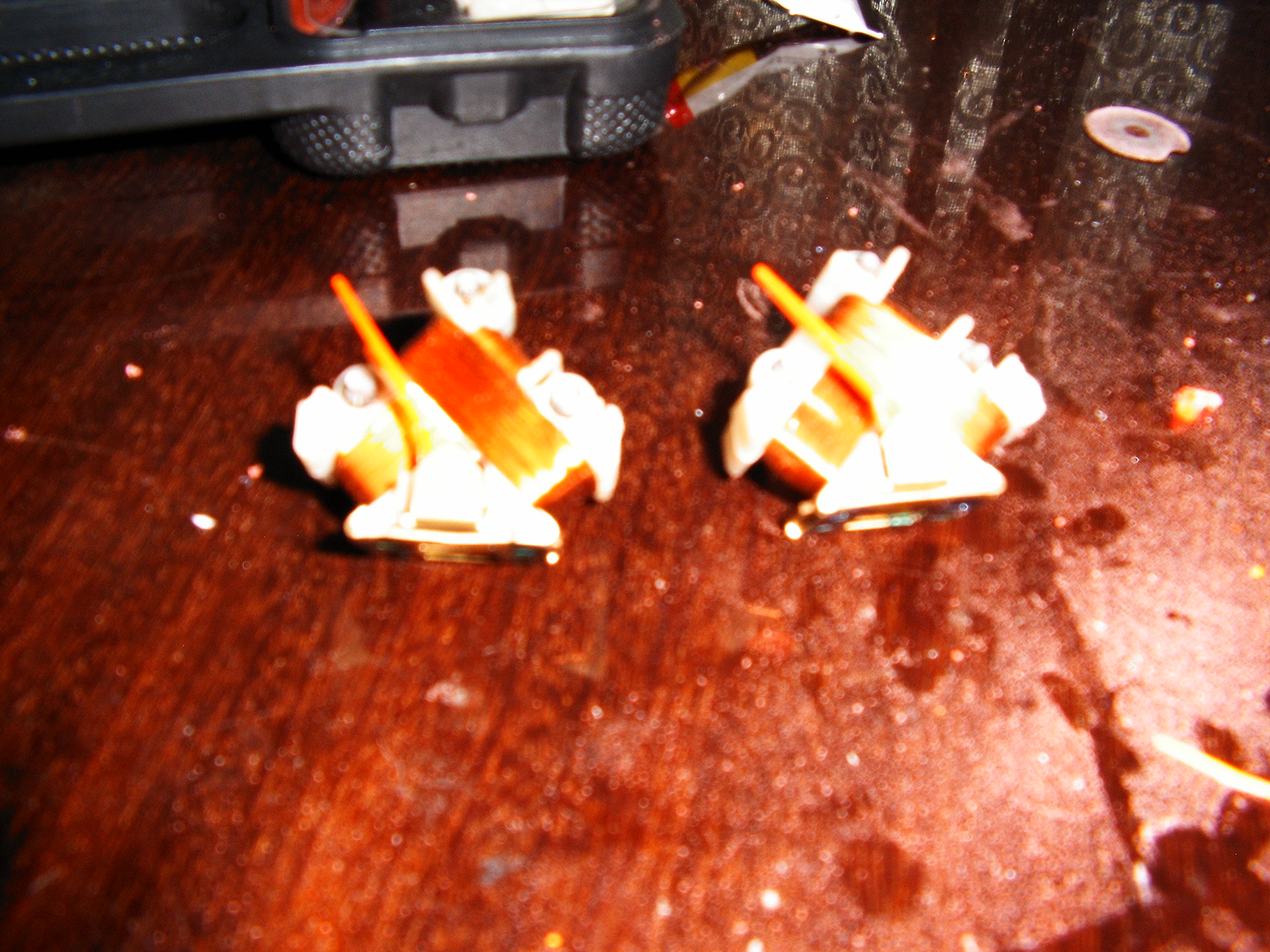
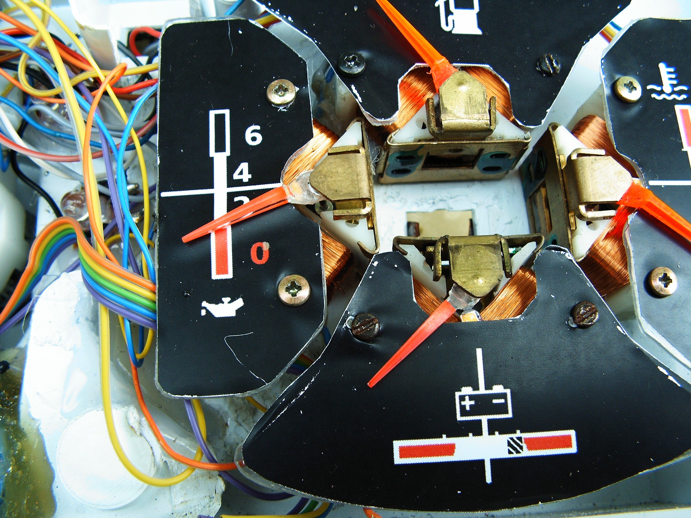
Close up view of the 4-gauge area. Middle hole is for emergency light signal led.
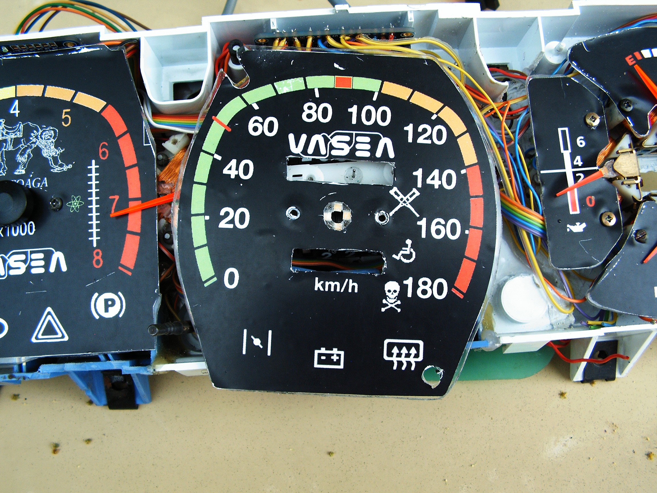
Speed meter and RPM+extra two gauges close-up view.
Notice the leds in the middle of the speed dial, under the pointer.
There are also leds under each pointer.
Dials were made from CD cases cut with the dremel tool.
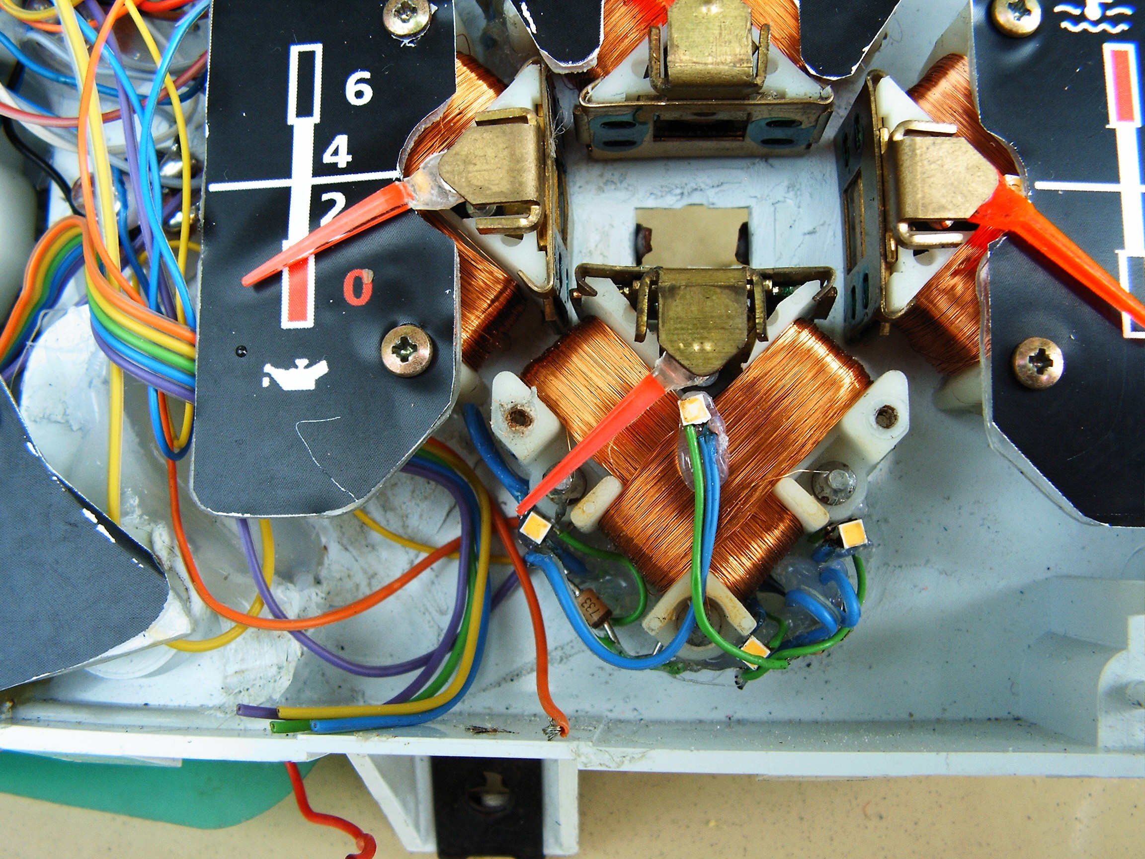
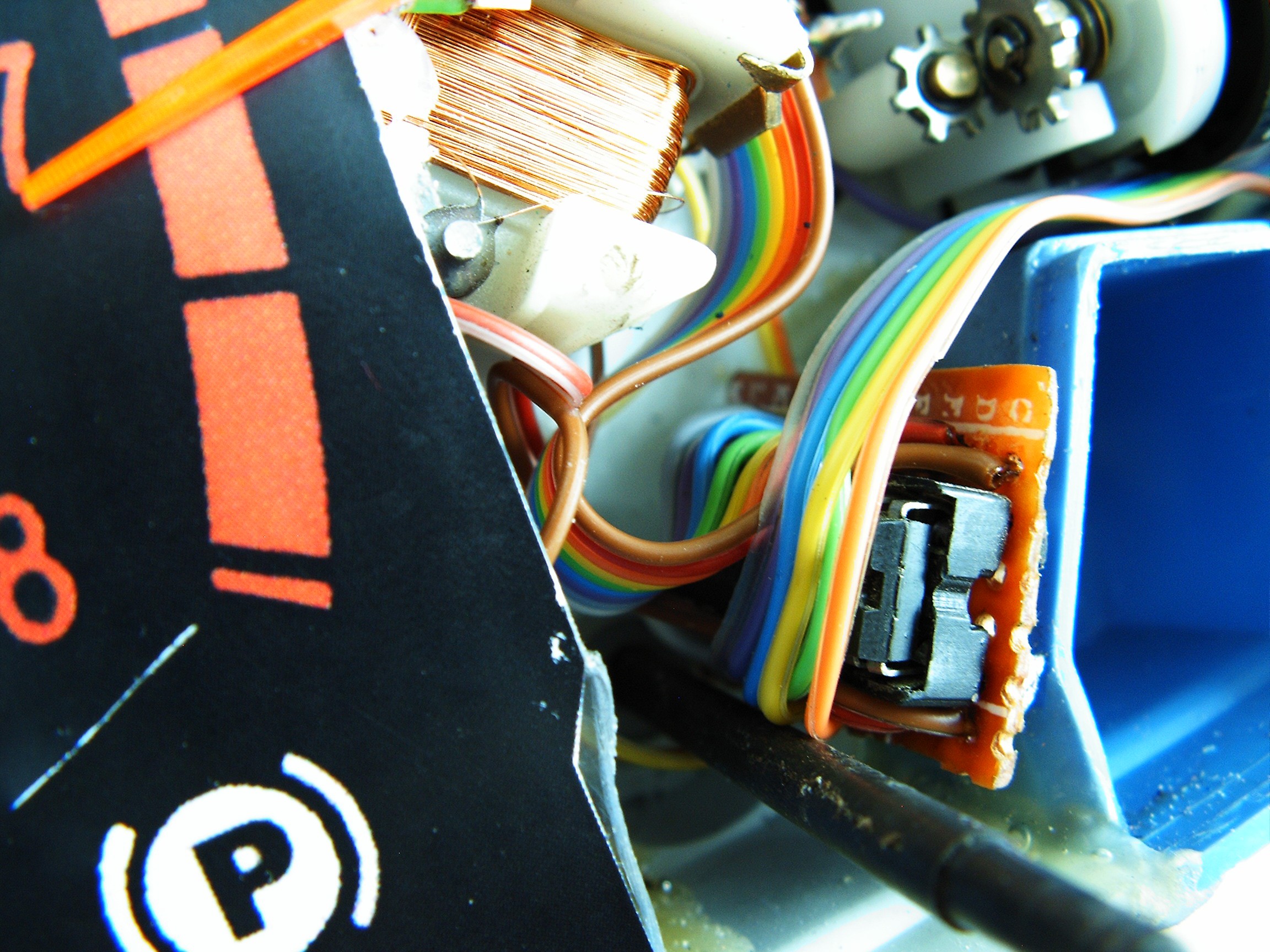
Again close view of the speed dial leds
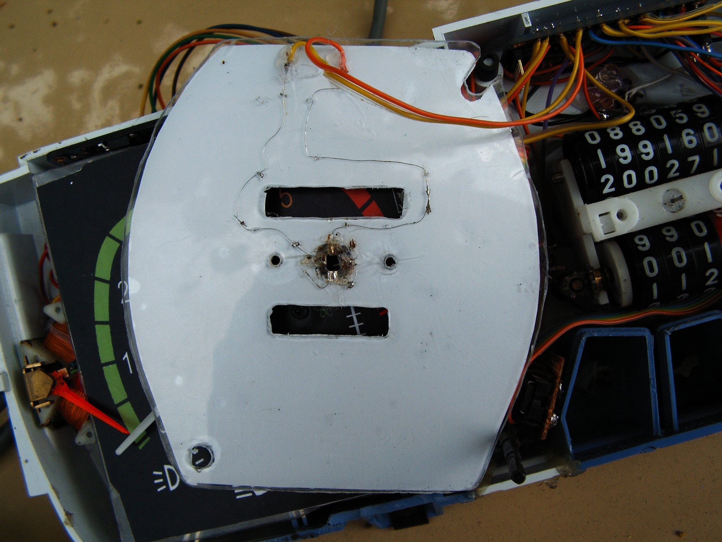
back side...
Back light for speed dial - there are some 5mm leds between the wires.
On top - led PWM controller
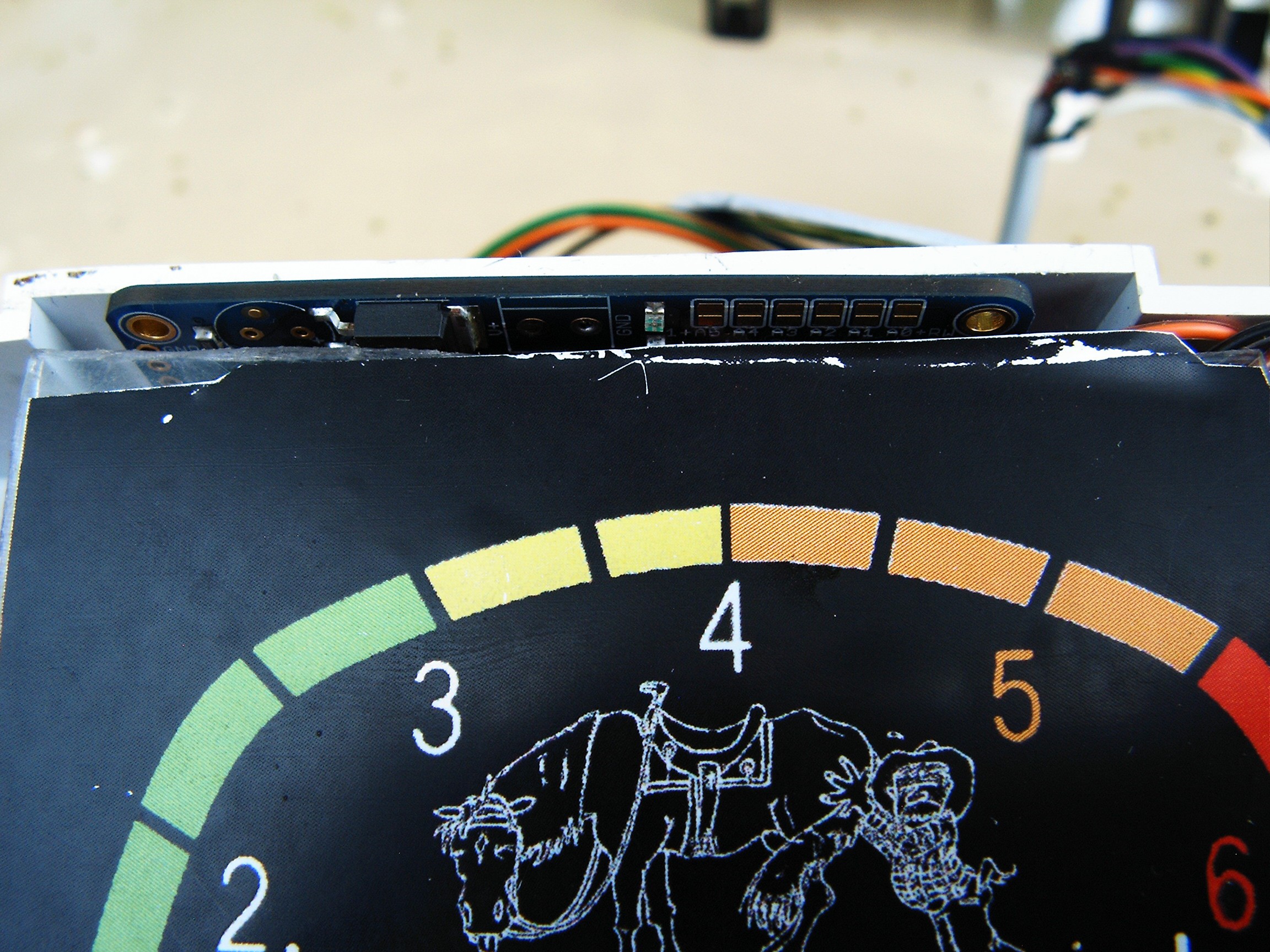
Gauge PWM controller, behind the RPM dial. And yes, that's an old lazy horse.
Can you see the leds under the pointer needles?
Battery dial removed, there are 4 leds.
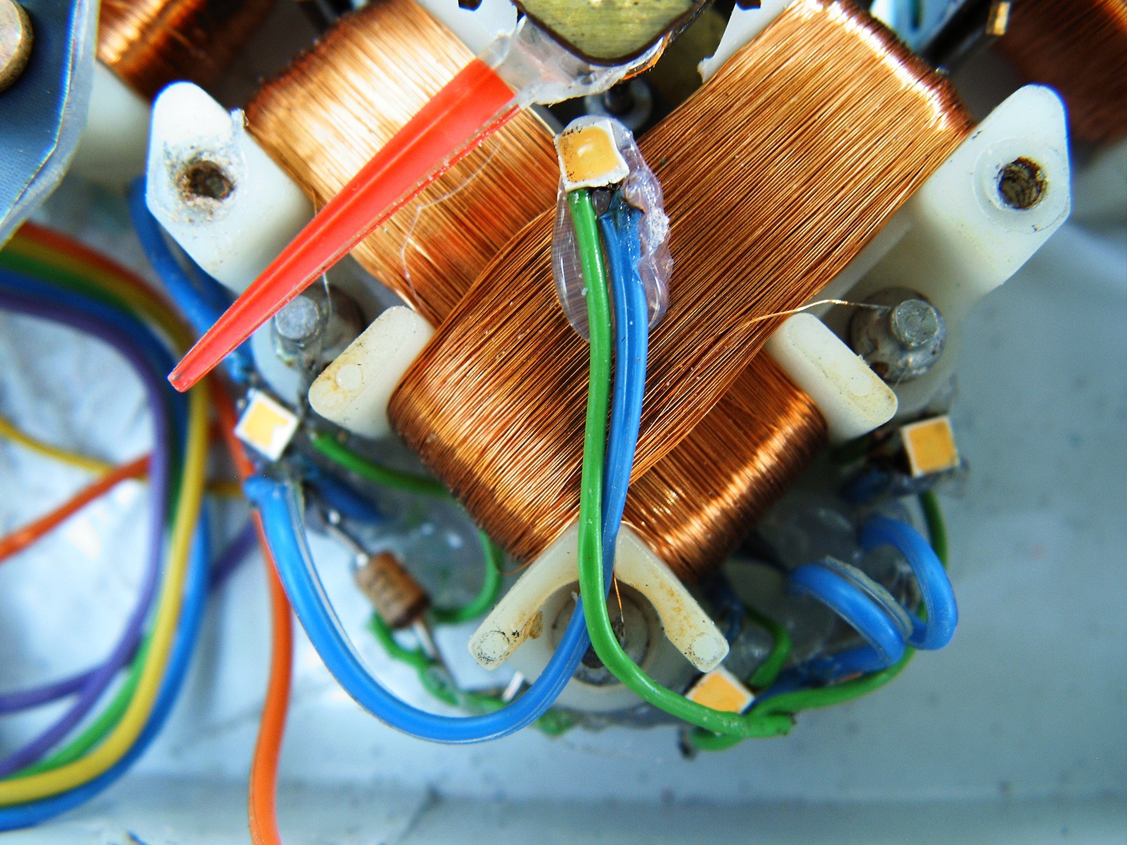
Close view of the leds.
Finally I started to learn how to adjust camera settings to focus properly.
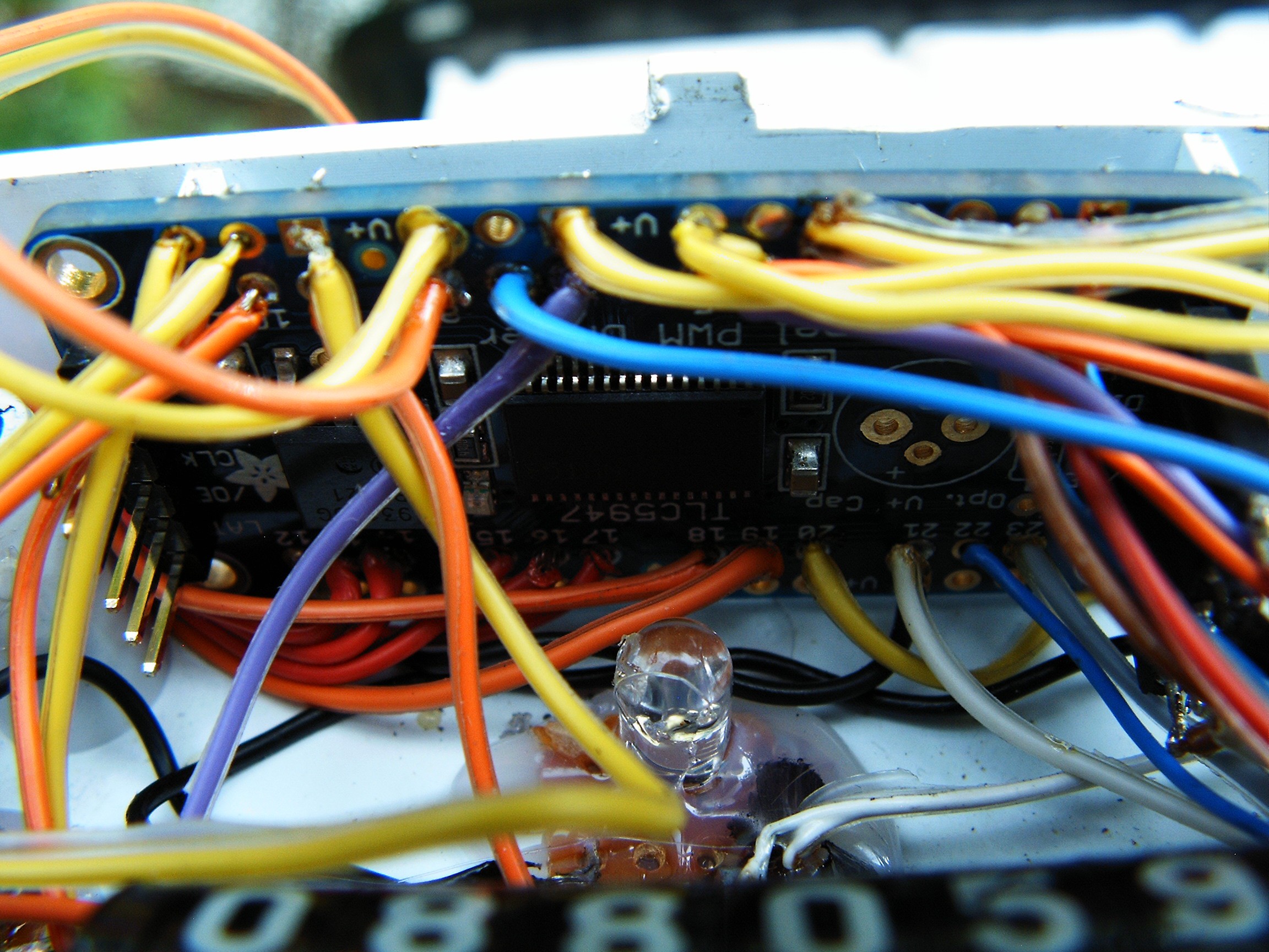
Again - close view of the TLC5947 LED PWM controller.
And of course the ULN2003A which converts 5V PWM signals to 12V so they are fit for the gauge. I manage to find a place for it, hidden in some corner.
[END OF TRANSMISSION]
______________________________________
kernel panic: improbability coefficient below zero
Discussions
Become a Hackaday.io Member
Create an account to leave a comment. Already have an account? Log In.