Close
0%
0%

Human Limb Tracking

A system that tracks limb movement of people who have movement disorders to assist in diagnosis and therapy

Similar projects worth following
A system using low cost IMU sensors attached to limbs to record movements of people with dystonia, cerebral palsy or other movement disorders. This information can be used to give objective movement data to assist in diagnosis and with therapeutic treatment . This is to replace current techniques that use video recording and (often) subjective observation of the recordings.

The system consists of multiple small wearable sensors, each containing an Inertial Measurement Unit (IMU) device.

The sensors communicate wirelessly to processing and display software that provide a browser based user interface.

The interface can display live 3D representations of the limbs, record movements over time and also record video of the person as they move.

Recorded motions (and video) can be replayed and analysed.

Recorded movements and video can be superimposed over live movement displays allow the system to train movements or compare movements to a pre-recorded 'ideal'

The aim is to produce a low cost, easy to use system to monitor limb movements.

I intend that the ideas, hardware, software and associated documentation developed as part of this project be available for anyone to replicate and use in the spirit of the MIT software license.

Basically I mean that to mean: if you want to build, implement, experiment with, use, market, make money from, donate expertise in, sell expertise in or modify a system based on this work, you should be free to do so, providing you appropriately acknowledge its source and respect the above intention.

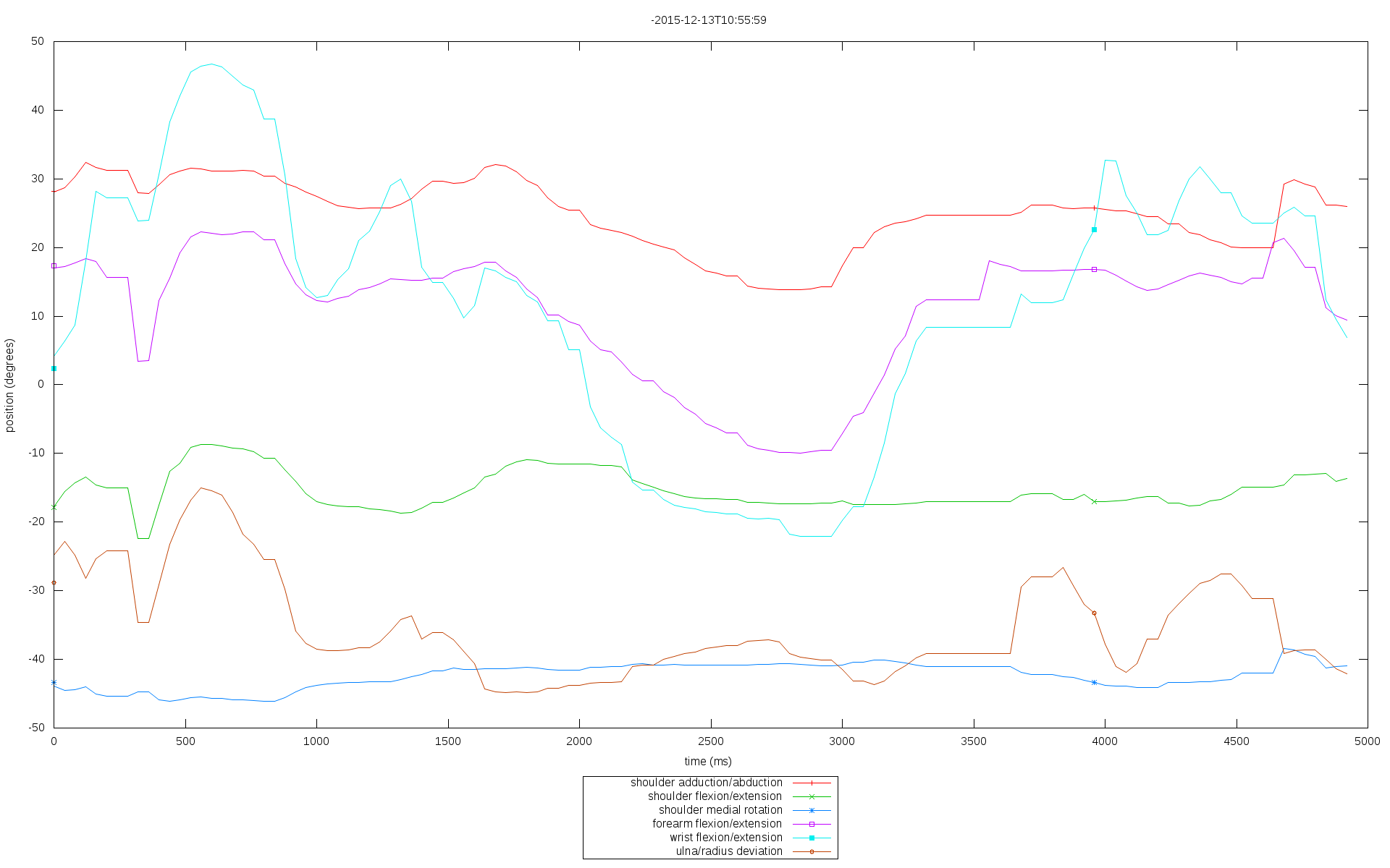
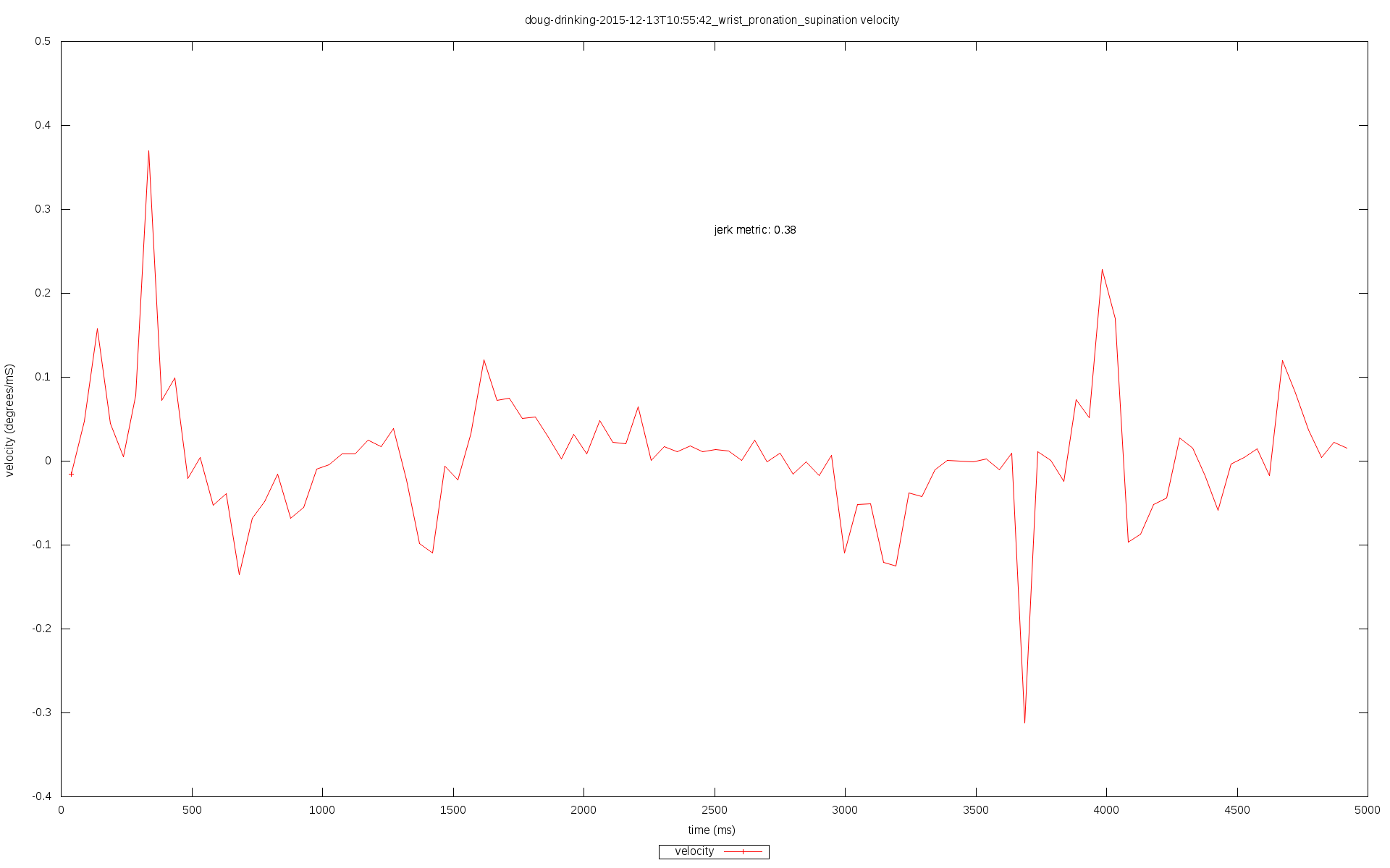
This is the second incarnation of the project. I made an initial version using MPU9150 sensors wired to a Raspberry Pi based controller device and sending its output to a Web User Interface. The system did work but was clumsy to set up and restricted in application primarily due to the fact that all sensors were wired and the processing of all the raw sensor data was done by a single microprocessor potentially limiting its expansion to large assemblies of sensors.

Video examples of the earlier system in operation:

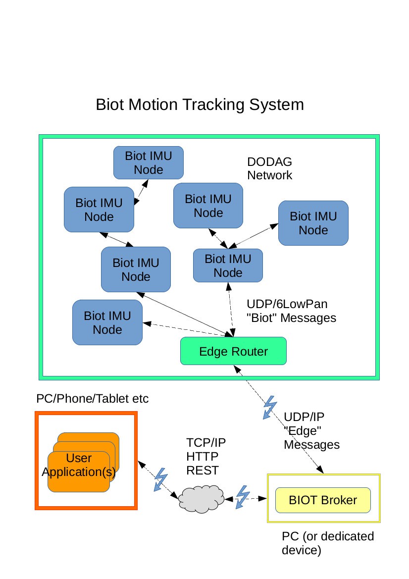
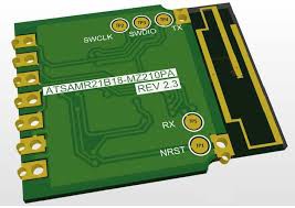
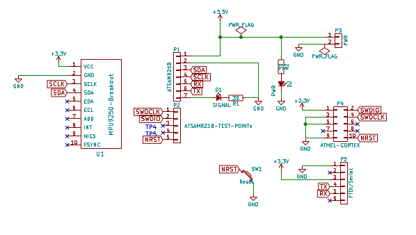
The current system uses MPU9250 IMU sensors, each combined with an ATSAMR21 microcontroller for each sensor node. Each node processes its own orientation data. These nodes now communicate using wireless (6lowPAN) to an edge router. The edge router (currently also using an ATSAMR21 based board) interfaces between the 6lowPAN network of sensors and a standard TCP/IP network.

The system has a simple REST web service API hosted on a PC that communicates with the edge router and provides the ability to read data from and send control data to the IMU nodes.

Finally a browser based user interface, uses the Web Service API, to record and display the movements and allow the user to control the system.

I am calling the nodes "Biotz" - little biological sensing internet of things thingys :)

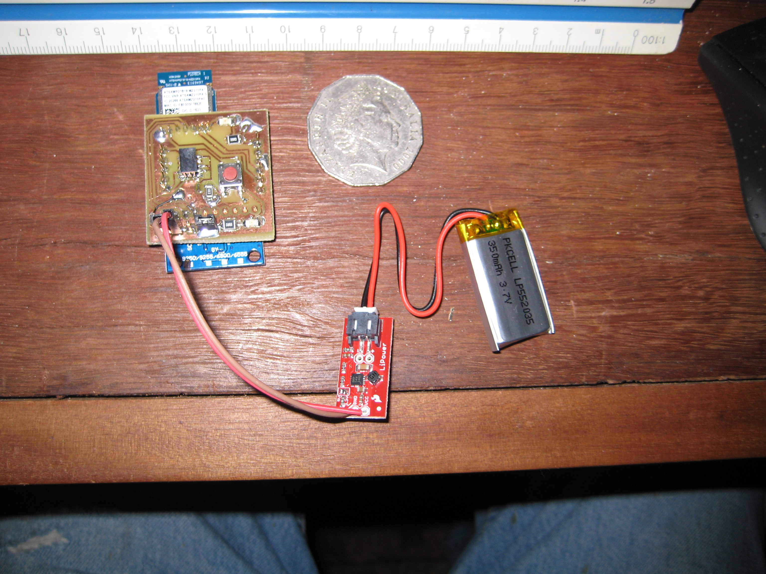
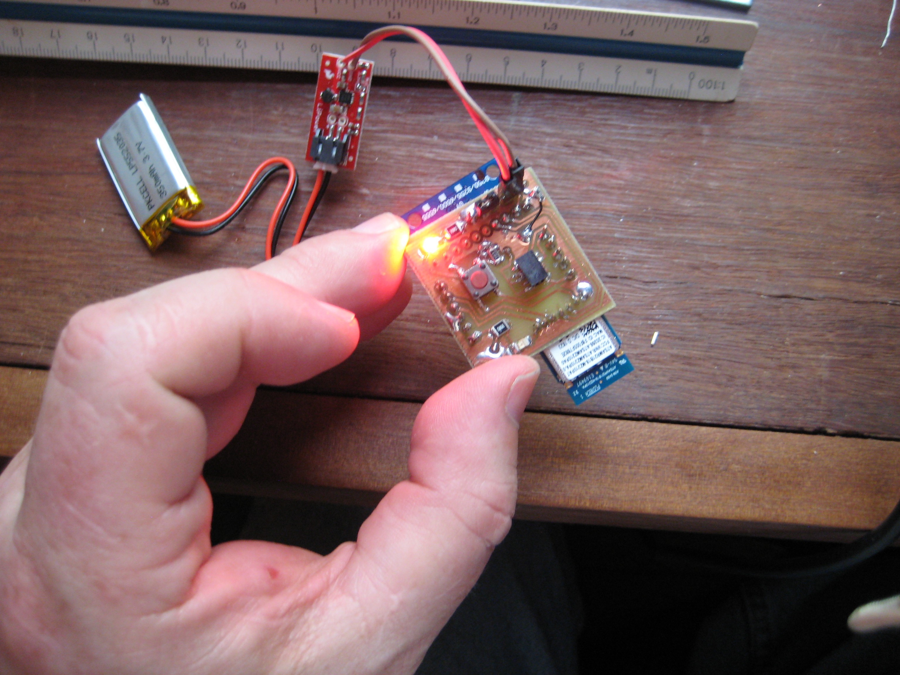
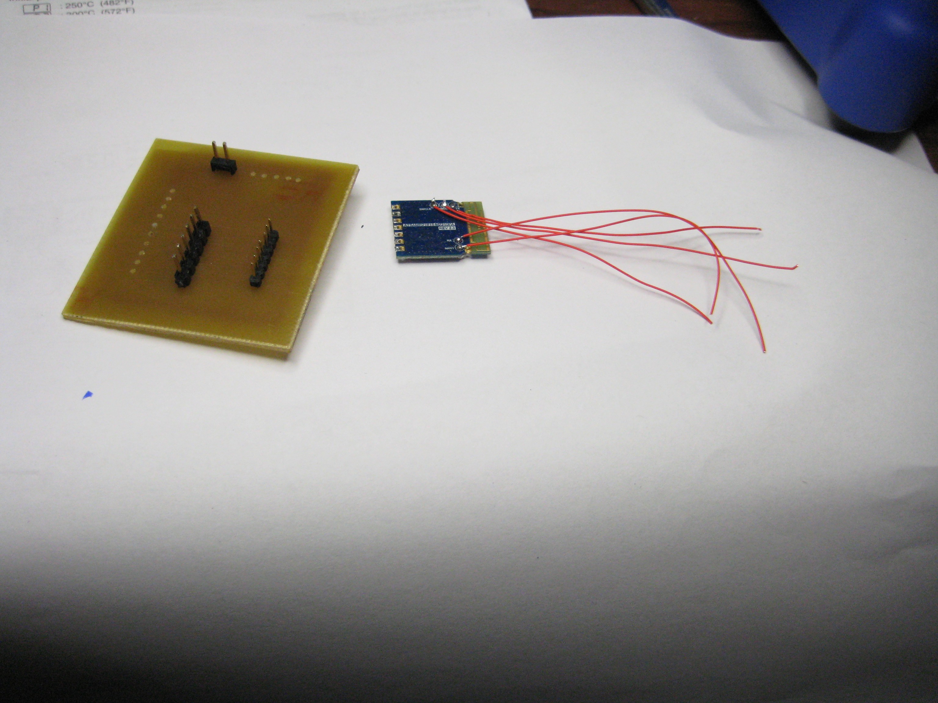
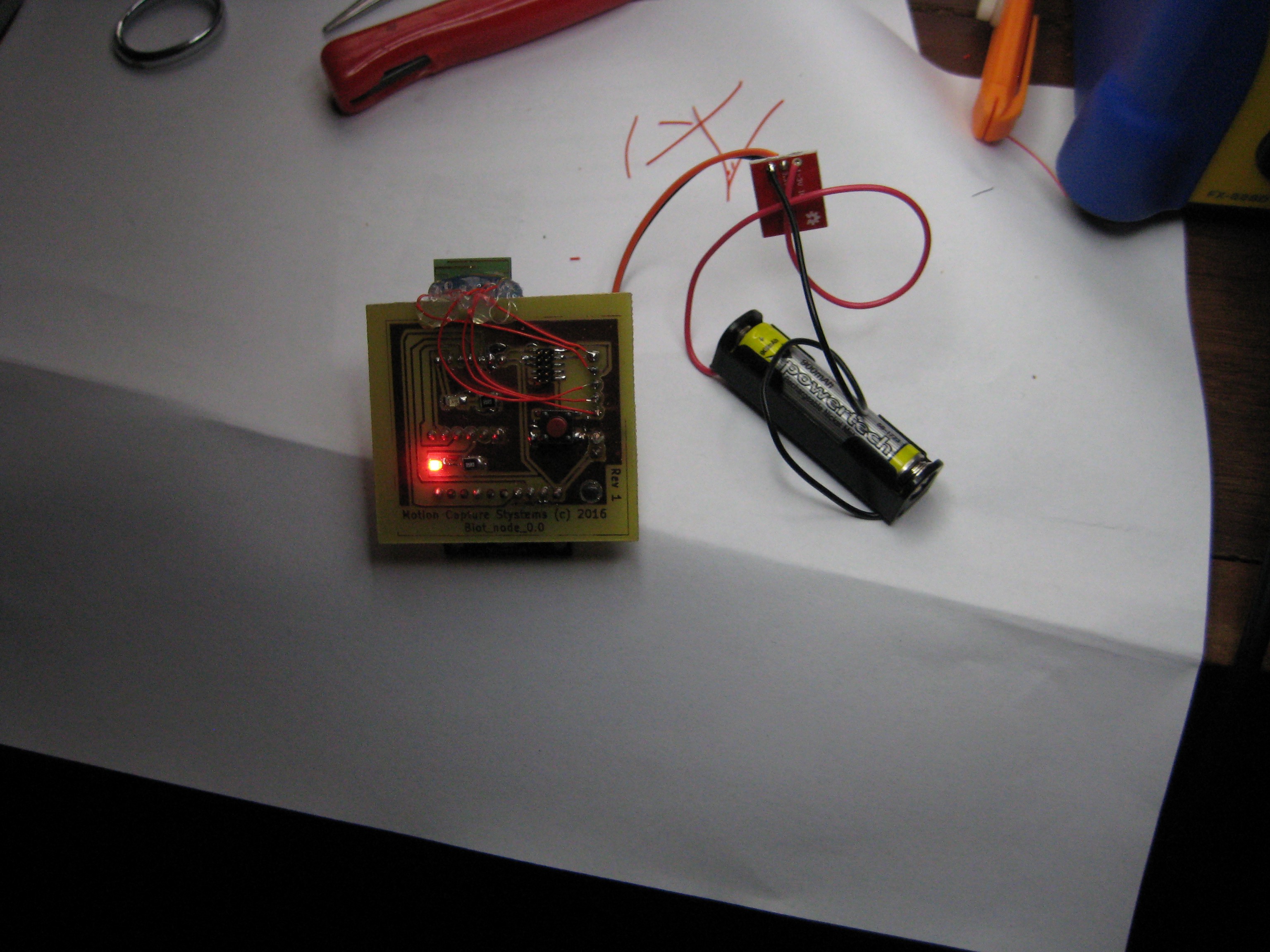
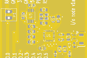
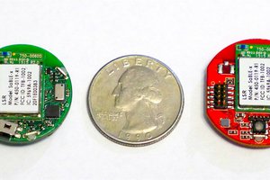
One of the current "proof of concept" wireless IMU sensor nodes - I need to reduce these in size:

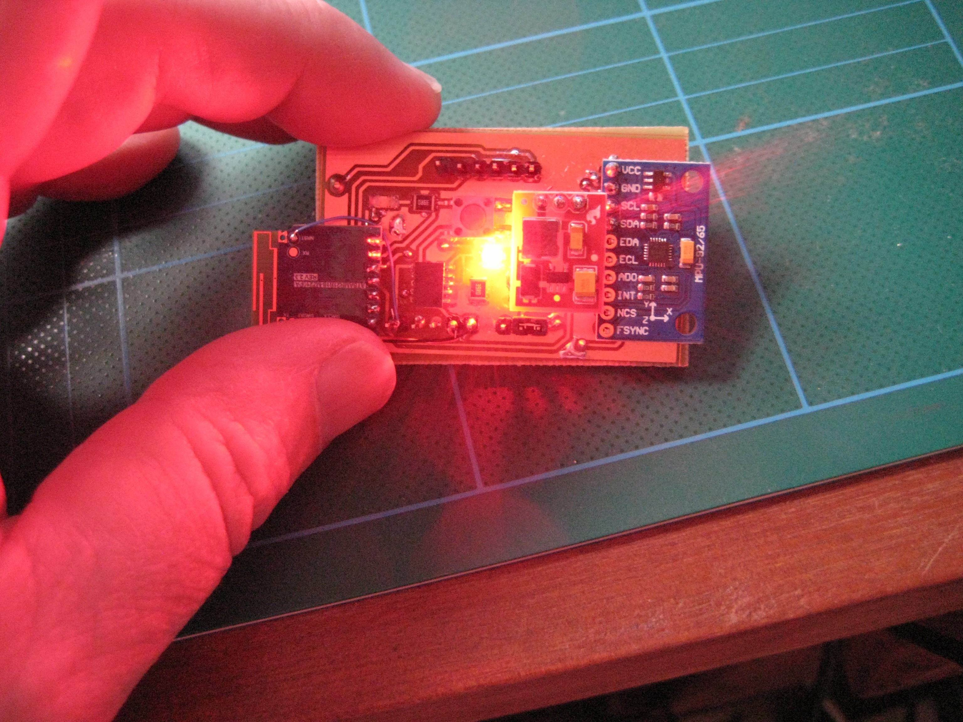
The current system does not (yet) have the functionality of the earlier "wired" version but should soon and it also should be much more robust and easier to use. It should also be more scale-able to situations requiring many sensors.

The code, documentation and files describing my hardware design should be available from this project page or my GitHub repository (if you think anything is missing please ask).

NB I am strictly an amateur when it comes to the hardware so I am happy to have people with better ability in that area give criticism or suggestions.

Biot System Description release-v-1.0.pdf

Biot System Overview and API/Messaging Specifications. First release.

Adobe Portable Document Format - 1.16 MB - 09/23/2016 at 04:45

Preview
Download

  • 16 × MPU9250 9 axis IMU sensors
  • 1 × ATSAMR21-ZLLK ATmel evaluation board for edge router duties.
  • 16 × ATSAMR21B-MZ210PA microcontroller/wireless module
  • 16 × Sparkfun 3.3v voltage upconvertor
  • 16 × PCBs + leds resistors etc Connectors and Accessories / Telecom and Datacom (Modular) Connectors

View all 6 components

  • Refactoring architecture

    Jonathan Kelly10/13/2017 at 02:20 0 comments

    have been refactoring code and architecture before seeing how system will handle the data from multiple nodes operating simultaneously.   I am concerned the bandwidth and reliability will suffer when I have multiple nodes.

  • Refactor of messaging protocols done - next steps

    Jonathan Kelly10/10/2016 at 06:44 0 comments

    1. I have rewritten the software to use the new communication protocols as per the specification document.

    The process threw up a few shortcomings with the spec but nothing major - mostly found I needed to add a few extra calls. I need to properly update the spec document to reflect the changes.

    The process of changing the protocols also picked up some problems with the system that was slowing down the communication speed and potentially dropping data. Coupled with the pruned back messaging size, the data flow between the various components should now be a lot more efficient. This seems reflected by what seems to be a smoother screen display (this a bit subjective though).

    The code still needs a big refactor as mostly I just replaced the communication interfaces and left the rest of the code untouched. It is still pretty hairy code.

    2. I have made a new node design, using a LiPo battery. My target is ultimately to make the node about the size of an Australian 50c piece. It is getting there. My fabrication skills are slowly getting better.

    The new node uses a 350mAh LiPo and a Sparkfun Boost converter (both sourced in Oz from LittleBird Electronics - https://littlebirdelectronics.com.au/ - happy to give them a plug - good to have a local company that stocks Sparkfun bits:)).

    3. I am looking at ways of mounting the nodes (+battery etc). I have bought some wetsuit neoprene material and am going to experiment with this to see what I can make up.

    Once I can get a workable attachment method I can start trying it out in situations closer to its end use environment.

  • Practical Use (older version)

    Jonathan Kelly09/23/2016 at 06:24 0 comments

    I thought I would add some older examples of how the system is used.

    The short video is showing the older 'wired' version of the system being used to monitor accuracy and smoothness of a simple task - the request was 'lift an empty glass to your mouth as if you were going to drink from it'

    the system recorded the movements using IMU sensors attached to the upper arm, forearm and back of the hand. It then generated a number of graphs of the motion.

    2 of the graphs of the above motion:

    rotational position of a number of movement axes over time. Notice how the 'wobble' of his hand as he puts the glass back down in the video is reflected in the graph - particularly the wrist flexion/extension and ulna/radius deviation.

    angular velocity of wrist pronation/supination

    This excerpt was from a trial done last year looking at the effect of the drug Baclofen on his dystonic movements.

    The above session was done using the first incarnation of the system using IMU sensors all physically connected by wires to a Raspberry Pi that was worn on the body that queried each of the sensors for their raw data, crunched that raw data from each of the sensors into a suitable form and passed the calculated orientations to the User Interface.

    In the new 'Biot' system currently being worked on, each sensor operates standalone and does the processing of its orientation itself and sends that calculated data wirelessly to wherever it needs to be displayed and recorded.

    It should hopefully be lighter, a lot easier to connect and configure and should scale better for operation with many sensors.

  • System Specifications

    Jonathan Kelly09/23/2016 at 05:20 0 comments

    I have finished writing the specifications for a newer and cleaner set of system APIs and messaging protocols.

    The current system interactions were tacked together on the fly as I was trying to work out how to make the system work and as a result are clumsy, difficult to develop further, hard to debug and generally inefficient.

    The new protocols have taken into account some of the things I learnt from getting the current system working and are better organised and thought through.

    I will need to refactor the system software to use the new protocols. This should clean up a lot of clutter and duplication though and generally make the system easier to develop.

    The specification document is at https://cdn.hackaday.io/files/10766460612544/Biot%20System%20Description%20release-v-1.0.pdf

    The document describes the model drawn below and specifies in detail the message protocol and REST API.

    Next steps:

    1. refactor the software to use the new protocols and API

    2. make the Biot nodes smaller and change them to use LiPo batteries

    3. work out a good way to mount the Biot nodes on the body

    4. refine the user interface (to at least have equivalent functionality to the early version of the system)

    5. start using and testing on live subjects

  • Proof of concept seems proved

    Jonathan Kelly09/19/2016 at 07:25 0 comments

    I have built several of the nodes, progressively making them smaller (as I get better at making and assembling the PCBs). At this point (based on how they behave) I think this architecture (using the SAMR21s and MPU9250 IMU devices connected via a 6lowPAN network) will work and is worth pursuing.

    Power consumption seems reasonably low - unfortunately a little bit too much for a 3v button battery though. :(

    Here are 2 of the most recent nodes showing their size. It is a bit hard to see but the UI is displaying both nodes moving in unison as I twist my hand about.

    and here is a quick attempt to hook them up to my arm using some velco straps just because I am impatient and wanted to see them doing something that will be closer to their end purpose.

    Basically they seem to work but now I need to look at making something more practical and closer to a usable product.

    Next issues to address:

    1. size and shape. The current nodes are still physically larger than I want and are awkwardly shaped making them hard to attach to the body. They also are a bit heavier than I think is appropriate. A lot of this is because of the AAA battery each node carries and the MPU9250 breakout board size.

    I am looking at moving to a flat LiPo battery that should result in a thinner, sleeker and smaller design.

    I also want to move away from the MPU9250 breakout board to mounting a MPU9250 directly on my carrier board as this will also save space. Unfortunately due to the pin spacing on the MPU9250 I will need to create a PC board with finer resolution than I currently can achieve (my 600 DPI laser printer cannot print the pads on my transparency without them running into each other :( ). This bit not yet urgent as I think changing away from the AAA battery and making a suitable mounting system is higher priority to get working first.

    2. Mounting the nodes on the body. I need to have a simple and easily attached way of attaching the nodes to various parts of the body.

    3. User interface. Currently my user interface is aimed at testing the nodes functionality, rather than being something that would be capable of being used to actually record and analyse body movements. This will need some thought and specification (although the UI I made for the earlier implementation of the project had much of the functionality I think I need to implement in the new system so can be used as a model for what I need).

    4. Edge router. Currently this involves booting up a SAMR21-ZLLK development board, hooked up to a FDTI/USB cable and running a SLIP network interface to give me connectivity between the node network and the 'real world' network. Ideally I would like something like a USB dongle that plugs into a PC and starts up or a small standalone wireless device that just needs to be turned on.

    5. Live testing of tracking, recording and analysing actual limb movements.

    Other Issues

    I need to look at is static discharge protection. Because the nodes are worn on the body and the person may be wearing clothes that may generate high static charges I am concerned the nodes may be vulnerable to damage from ESD. (I think I killed 2 of the atsamr21b18-mz210pa modules last week while I was wearing a synthetic jumper that I know builds up a bit of charge. I got a small spark between my hand and desk lamp not long after 2 of the nodes stopped working - a cold dry windy day as well so I believe it was ESD that killed them). Designing to protect from ESD is not something I have any experience with so I will need to research it.

    Tidying up the software. Currently the software development has been directed by experimentation rather than specification. I want to spec out the various APIs, communication protocols and software functionality. This should make it more robust, scalable and maintainable. It will involve specifying node to node messaging, node to edge router communication, the web service API and the UI functionality. Up until now I have just added bits as I needed them but there is a great lack...

    Read more »

  • Slightly tidier biot node

    Jonathan Kelly09/02/2016 at 04:48 0 comments

    I have tidied up the board for my second biot node, mounting the battery and up-convertor onto the PCB.

    Annoyingly I have run out of ATSAMR21B18-MZ210PA modules so can't build any more at the moment :(. They have been on back-order from my supplier for a few weeks. Not sure how long I will need to wait.

    I could start looking at rolling my own board using a standalone SAMR21 chip rather than the prebuilt module but that involves a jump up in my fabrication and design skills and also means the issue of radio compliance/certification might need to be considered.

  • Proof of concept wireless IMU node

    Jonathan Kelly09/01/2016 at 04:41 0 comments

    So far I have been using ATMEL evaluation boards (the SAMR21-XPRO and ATSAMR21-ZLLK boards) to develop the IMU sensor nodes but I will need to move towards a small purpose built, battery powered module incorporating an IMU sensor and microcontroller.

    I am still building up my design and fabrication skills and so decided my next step would be to move to an intermediate 'proof of concept' sensor node using easily assembled bits.

    I took an "off the shelf" MPU9250 IMU breakout board (the MPU9250 appears to be superseding the MPU9150 that I have being using as sensors up until now), an ATMEL ATSAMR21B-MZ210PA microcontroller/wireless module, a Sparkfun 3.3v voltage upconvertor breakout board and made a small PCB that holds the IMU and microprocessor along with some leds to indicate power to the node and a 'heartbeat' from the microprocessor.

    The node runs off an AAA cell and seems to work fine (after a few "learning experiences" making dodgy PCBs) . It is not my final design but will allow me to do some more experimentation and planning of the next steps.

    The ATSAMR21B-MZ210PA has minimal pins available and to program it.

    I need access to the RESET, SWDIO and SWCLK test points that are not exposed on the main module output pads but are available as test points on the underside of the board. I soldered some wire wrap wire to the test points so I could get access to them. This allows me to program the microcontroller using the Atmel 'Cortex' 10 pin header and Atmel-ICE programmer.

    It appears to work!

    The PCB is schematic is simple - it is mainly a carrier for the IMU and microcontroller modules:

    The code that runs on the microcontroller and the PC communication and browser display applications are available at GitHub "Biotz" code.

    You will need an edge router - I am using an ATSAMR21-ZLLK evaluation board and the code that runs on that is in the above repository (along with README info on how to set it up).

    The code on the microcontroller runs under the RIOT-OS operating system. I have forked a copy of RIOT so I can add the boards I am using and functionality I need. It is not at the same coding standard as the 'real' RIOT-OS code - it is hacked enough to get it to work for the prototypes. My forked version is at hacked version of RIOT-OS.

    Don't expect production ready code! It is really scrappy, feel free to use it but don't expect it to be robust! Also it is under currently active development so I may break things at times :(

    My next steps:

    1. make a few more of the 'proof of concept' nodes to see how well they interact with each other

    2. start refining the node design into something closer to what I am envisioning - something quite small, lightweight and physically robust, that can easily be attached to the body.

  • Changing architecture

    Jonathan Kelly08/13/2016 at 01:10 0 comments

    Having wires to each sensor introduces problems with the wires getting tangled and in the way when moving, connector integrity, issues with transmission of the I2C signals for sensors attached a long way from the controller, the need to wear a controller on the body and difficulty attaching the sensors.

    I want to move this to a wirelss solution.

    I have been experimenting with using ATMEL atsamr21 type devices. These devices combine an ARM processor with a low power 2.4GHz wireless module and are being pushed for use in "IOT" type applications.

    They have low power consumption, are cheap and small.

    The small size of the units means I think I can create a small node with an IMU (Inertial Measurement Unit) , processor and wireless, that would remove the need for the controller device (the current body worn Raspberry PI) and move a lot of the maths processing of the IMU data to the sensor node itself.

    This will simplify things a lot.

    Currently I have a hacked up system working that uses the MPU9150 IMU sensors, hooked up to various atsamr21 boards (atsamr21-xpro and atsamr21b-mz210pa) to get the code working and see if it is feasible.

    I am using the RIOT OS operating system https://riot-os.org/ to manage the nodes, it also allows me to access a shell like interface to each node while I am working. I have forked a version of RIOT to allow me to add support for the XPRO and 21b-mz210pa boards plus add some bits I need to make it work.

    The processor on each board is calculating quaternions representing the physical orientation of the IMU chip it is connected to and sending that using a 6lowPAN network to a edge router (currently an ATSAMR21ZLL-EK evaluation board) that connects to a PC running a web service allowing browser applications to track the sensors.

    The next step is to move to making a small node that houses the processor, IMU and power source that can easily be attached to the body.

    I will update the parts list and links to code for my forked RIOT and the nodes themselves on GitHub soon.

  • Current state of play

    Jonathan Kelly04/08/2016 at 01:15 0 comments

    This is a bit of a ramble... sorry


    Some background

    My youngest child has a form of athetoid cerebral palsy that causes uncontrolled movement.

    I am interested in ways I can use technology to help overcome some of the problems that condition causes.

    I started this as a part time project over 18 months ago.

    The original idea was to look at providing alternative ways of sensing exactly what your limbs are doing (particularly if they are not moving how you are intending to move them!) to help gain better control of your body.

    One of the initial inspirations was how sometimes an unintentionally flexed muscle would relax if you stroked lightly the associated 'opposite' (or 'antagonist') muscle (eg if the bicep flexed, stroking the tricep at the back of the arm would seem to often help release the bicep) .

    What I was initially interested in looking at:

    1. ways of sensing when a muscle was unintentionally flexed and perhaps applying automatically some form of tactile feedback to the antagonist muscle (eg a vibration).

    2. ways to provide additional proprioceptive feedback about limb movement (eg visual, tactile, auditory etc) in addition to the feedback our body gives normally.

    3. ways to measure long term changes in the way the condition manifests itself, particularly when evaluating various therapies.

    The first step in exploring these ideas, was to develop a system to accurately and unobtrusively measure limb motion.

    So I started doing that.

    That is this project.

    It has been going about 2 years.

    Where the project is now:

    1. I have a working prototype. It is a bit rough and clunky but proves the system works.

    2. it was used whilst trialing a drug treatment that can sometimes help people with dystonic movement disorders. (This was done in addition to the standard evaluation technique that involves experts taking before and after videos of various tasks that typically are used to diagnose dystonia). Unfortunately the drug trial was stopped part way through as it appeared subjectively to those involved to be causing more clumsiness and difficulty controlling movement rather than improving it.

    The system did appear to also indicate more objectively a worsening of control that confirmed to me it was a potentially useful tool.

    Where I am (personally) at now

    After talking about what I was doing with friends and acquaintances over the last 2 years I started to wonder if something like this could be turned into a commercial product and what would be involved. I foolishly started to think of perhaps making a company that produced motion capturing systems.

    Meanwhile, I hadn't done a lot of looking at what was out in the real world for some time - I was too engrossed in the nuts and bolts of getting it working.

    I recently discovered that since I started playing with the technology, many people have been doing similar things (including several projects on this site) and I also saw that other's have recently come to market with commercial devices using IMUs for sensing of limb postion.

    Which I should have realised was to be expected - IMUs and tracking your body are a pretty obvious match!

    But to me this came as shock (silly me!) and was discouraging but then I thought - why am I doing this? To make a commercial product? or to explore how I can assist people with movement disorders?

    It is the second - I had lost sight of the motivation - I am not trying to make a business. I want to see if I can make something that can assist the day to day life of people (like my son).


    So where I am heading with it:

    I now want to start looking at the other initial spurs that started me on the project: ie

    1. sensing if a muscle is unintentionally flexed

    2. providing feedback to the person (eg automatic tactile feedback to antagonist muscle pairs and alternative proprioceptive feedback to build better unconcious understanding of where your limbs actually are.

    and integrate those ideas with the existing tracking system. I also need to refine the system to make it less physically clunky and more...

    Read more »

View all 9 project logs

Enjoy this project?

Share

Discussions

Jonathan Kelly wrote 07/31/2016 at 21:23 point

Thank you and sure - happy to talk.  I am currently working at turning the sensors into wireless units, each one consisting of an IMU sensor and a wireless/processor (currently experimenting with Atmel's ATSAMR21G eg see http://www.atmel.com/Images/Atmel-42486-ATSAMR21B18-MZ210PA_Datasheet.pdf).  The idea is the sensors will be stand alone units a bit bigger than a large coin. 

It will remove both the need for wires from the sensors to the body worn control unit and also the controller unit itself as each sensor now has the computational power to do its own motion processing of the IMU output and send its derived orientation directly by wireless to whatever interfaces or applications are monitoring the combined motions.

  Are you sure? yes | no

Cody Crockett wrote 09/26/2016 at 04:24 point

This is AMAZING work. I have so many questions. What exactly are the sensors "sensing" ? Is it measuring the muscles activity, such as muscle contraction intensity? WIll the sensor measure muscle activity with isometric muscle contractions where the limb does not move in space? Are there MMG capabilities with this sensor?

 Thanks!

  Are you sure? yes | no

Jonathan Kelly wrote 09/26/2016 at 05:18 point

Hi Cody.  Thank you.  Amazing is probably a little strong but I will take it anyway  :)

The really clever stuff is actually in the components I use like the IMU units and microcontroller - I am just joining bits together.

Currently the sensors simply measure orientation in space using Inertial Measurement Units (IMUs).  

IMUs measure rotation by a combination of means, by gyroscopes, by measuring the direction of gravity, and measuring the direction of the earth's magnetic field.   I am using MPU9250 IMUs that are amazingly cheap. 

Once I know rotation of the each I can determine limb positions by using that data and knowledge of how each of the limbs are attached to each other.

IIn the future I want to experiment with incorporating 2 particular capabilities, the first some form of myography (as you suggest) and the second is some form of proprioceptive feedback by adding some form of stimulation to the limb (eg vibration).  This was one of my original motivations for starting the project but adding that is however is still a long way down the track.  

I want to get the orientation measurement system working well first as this is a measure of the actual physical behaviour of the limb - in a sense a measurement of the 'outcomes' and if I can get a simple robust system that can accurately do that it will have standalone benefit in and of itself.   

Those other 2 relate to how the body is trying to achieve those outcomes (for myography) and how the outcomes may be better controlled and monitored by the person (the proprioception feedback idea).  Without a measure of outcome (useful in itself) the other 2 ideas will be more limited in what they can do. 

  Are you sure? yes | no

Tyler Berezowsky wrote 07/31/2016 at 15:32 point

I really dig your project. The sensor module I've been developing has a 6 axis IMU, but it would be pretty easy to update it to a 9 axis. It would be interesting to talk in a month or two and work together. 

  Are you sure? yes | no

Similar Projects

Does this project spark your interest?

Become a member to follow this project and never miss any updates