0%
0%
NanoEgg Music Synthesizer
A powerful little music synthesizer with a classic look!
 T. B. Trzepacz
Become a Hackaday.io member
Already have an account? Log in.
Just one more thing
To make the experience fit your profile, pick a username and tell us what interests you.
Pick an awesome username
hackaday.io/
Your profile's URL: hackaday.io/username. Max 25 alphanumeric characters.
Pick a few interests
Projects that share your interests
People that share your interests


 In order to access those pins, I needed a flat flex connector. I didn't want to unsolder the one from the sample. So I ordered them.
 So I needed to make an adaptor. Since the pin pitch doesn't fit in standard protoboard, I had to find a way to mount it.
  I have a bunch of protoboards I got for free from PCBWAY with my last order, but they had contacts in the edges that didn't fit the connector pin pitch either. So, I took it out to the garage and dremeled off the extra copper layers.
 Soldering it was kind of a pain, because wires had to go between the connector pins. Trying not to bridge the connections was tricky.
 So now I have it hooked up to the teensy and I can work to determine what the pins mean.
 I used the Arduino keypad library and the incorrect information I got from the manufacturer to finally determine what all of the key buttons were. There are two buttons per key, and the timing difference between button hits determines how fast you pressed the key down. I still have to write a library to handle that timing.
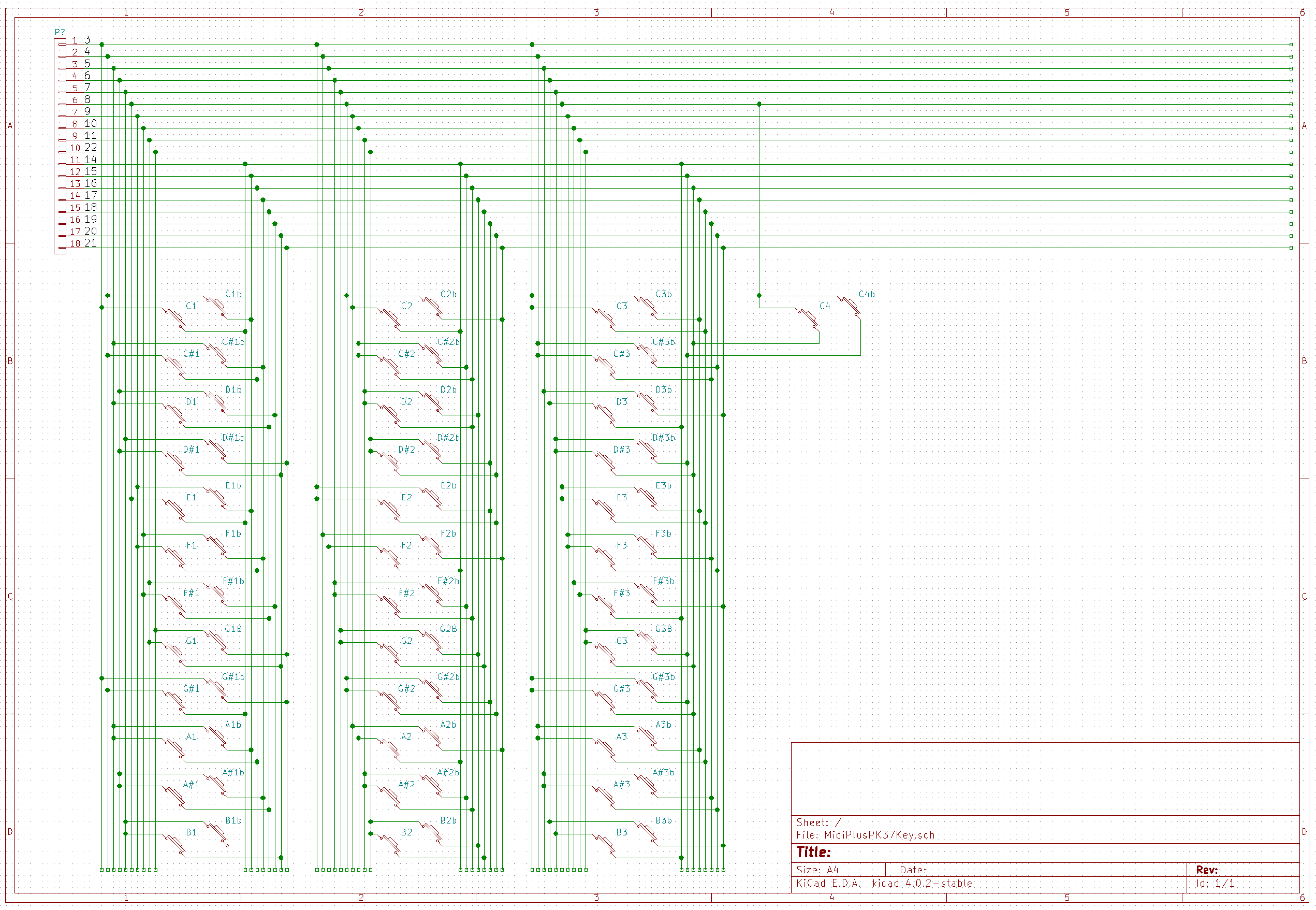


 More test prints were made.
 After many experiments with using cookies and various jigs to print the black keys in two parts, I decided to print the keys right side up with support material. Here it is used from the bottom to show the support structure that Bruce was able to set up. I think he was using Cura for that, although we did play with Simplify 3d a bit for that.

 When the 3d printed objects come off the press, they are very messy, and I have to work at them with a knife to remove all the excess plastic (aka sprue) to make a smooth-ish object.


 lawnmowerlatte
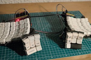
 David H. Bronke
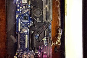
 Ari
Ari
Hello !
I've just finished a synth that share some similarities with yours : teensy audio lib, and probably the same inspiration source for global design... ;)
I've used the keybed of an old electronic organ from the 80', but I'm thinking about the next project, and dream of something easier to work with. Of course there is Fatar who make greats keybed, but it seems unlikeliy they will sell low volumes...
Would you share the name and contact of the manufacturer you bought yours from ?
Thank you !