 w_k_fay
I wanted to build a power supply but soon ran into the problem of how to test the design. I realized that before I could build a good power supply I would need a constant current load to evaluate what I was building. So after some searching and head scratching I came up with this.
How it works:
The load has a 1 ohm shunt, made up of ten 1 watt 10 ohm resistors. Ohm's Law says that the voltage drop across the shunt divided by the resistance (of the shunt) will give us the current being drawn by the load (in amperes). Using a 1 ohm resistor means that we need to divide the voltage by one to obtain the current. Therefore we can measure the voltage with a voltmeter and it will equal the current in amperes. So we can use any old voltmeter as a ammeter for the project.
The ten turn pot sets the load by providing a voltage between 0 and 2.5 volts to U1B which acts as a non inverting amplifier. The value of the shunt means that 1v equals 1A. U1A is a buffer and is not essential to the operation of the circuit, but op amps usually come two to a pack so why not put it to work. U3 the TL431 is a precision voltage source and it supplies a precise 2.5v to RV1. We really don't need the TL431. We could just use a resistor divider to divide the 12v down to 2.5v but I bought 20 of them on eBay for a buck and damned if I'm not gonna use them.
The non inverting amp U1B tries to keep the inverting and non inverting inputs equal by varying its output. The non inverting input is set by RV1 and the inverting input is set by the voltage feeding back from the source of the MOSFET. The MOSFET source is attached to the positive side of the shunt so the source of the MOSFET is therefore equal to the voltage drop across the shunt. So if we set the non inverting input of U1B to 1v the op amp will apply the necessary voltage to the base of the MOSFET to obtain 1v at the MOSFET's source, which gives us 1v across the shunt equaling 1A of load. Damn that's complicated !
C4 and R12 form a low pass filter that stops the MOSFET from oscillating. The values and necessity of this filter will depend on your circuit. I found that I had a 1v peak to peak oscillation at a 3v input. The MOSFET can be just about any N channel MOSFET you happen to have. This one came out of a dead ATX power supply and free is simply the best type.
The last thing that needs explanation is power dissipation. Power equals current multiplies by voltage. The Power dissipated by the shunt at 2.5A will be 2.5A multiplied by 2.5V giving us 6.25W and this is the reason why I an using 10 1W resistors. Also note that 10 1W cost less that a single 10W resistor and I have some 1W resistors in my parts stash.
Power dissipation for the MOSFET is a little trickier. If we are testing a 20v power supply the voltage drop across the shunt is 1v at 1A so the voltage drop across the MOSFET must be 19v. So the power dissipation is 19v multiplied by 1A giving us 19W. At 25v and 2.5A the power dissipated would be 62.5W and that is a massive amount of heat to dissipate.
The MOSFET will need a heat sink and a fan. So I have allowed for a fan in the design. Just for fun lets say you use a small 30mm x 35mm heat sink like the ones on eBay. The free air dissipation is a rise of 15/C for every watt of heat. Say a max of 60w and a rise of 15/C per watt, the heat sink should reach a toasty 900/C. So that isn't going to work. Fan cooling this heat sink lowers its dissipation to about 4/C per watt. So if we run the load at say 16v and 1A we would get 15W of heat causing a 60/C temperature rise above ambient. That is probably ok. So long story short get a big heat sink and a fan if you want to test big power supplies, and get a few extra MOSFETS just in case.

 Jakob Wulfkind
 Paul Andrews
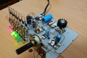
 mosaicmerc
Hi, this is a nice and inspiring project.
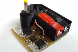
Can I ask for the single channel hom-made power supply that it's seen in one of the pictures? The one with the gray plastic enclosure: I see there are three pots which I presume that are intended for adjusting the voltage and current. Is this an off-the-shelf kit project or a custom design?