In early days when mobile phones began to be popular their chargers was linear with 50 or 60Hz transformer and four diode rectifier. These transformers has a high series resistance (main is about 10 ohm) so the output voltage falls very quickly after loading.
The disadvantage of it is they (as itself) are not suitable where constant voltage is necessary but can be rebuild that and even catch some advantage out of it.
Little numbers:
Consider charger with 3.7v/350mA/1.3W output parameters
This charger has no-load voltage after recification about 13v. After loading with 350mA the output voltage drops to about 3.7v.
Little theory:
The main idea in linear regulation is to drop an excessive voltage on some series element, ussually resistor or CE of transistor.
This drop generates a heat so this element must be enough power rated.
The worst situation becomes when we try to supply a high load (low ohm) with low voltage. Than we must drop the most of voltage from power source, i.e. the most of power is waisted on series element transfered to heat.
The advantage I mention in beginning is the our transformer help us to create this drop after we try to load it with high current (remember the falling of voltage) so less heat on series element we get.
Build a regulated supply:
First of all you cannot expect you get a professional laboratory power source for supplying power-leds, motors or audio amplyfiers.
But can build a pretty cool power source with low ripple for supplying analog op-amp circuits, logic gates/ICs or transistor experiments up to 1.3W.
In analog technique you offen need to supply circuits with more than lets say 12v so I add a voltage doubler next to one way rectifier. A rule, if you need a power supply with output lower then 6v use rectifier and if more switch voltage doubler on. Keeping this eliminates the heat on series transistor.
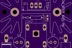
The doubler is also used to boost the voltage for supplying zener diode. The feedback to controll output voltage is taken from 10k R2 potentiometer. The voltage at R2 viper controls Q1 Ic current and thus regulates the Q2 Ib in negative manner.
Since the Q2 drops the voltage it should be mounted on small heatsink.
Results:
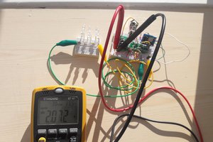
The output ripple of this power-supply is less then 5mV. Since there is used one diode rectifier only it cannot be expected to get full transformer power on output. I tried 50ohms load at 7V output (doubler off) and the results was excellent.
Using schottky diode in rectifier moves the output voltage top limit about 0.5V higher.
The two way rectifier is not suitable due to lack of voltage for suppling 18V zener diode after loading the output of power-supply (one way rect. let the one period "free" for boosting voltage to C3 capacitor).
A current limiting function is based on limiting the Q2 base current with 4k7 resistor so in worst case (output shorting) the output current cannot be more than about 600mA (exact current depends on Q2 beta).
Ib_Q2 = (18v-0.7v) / 4k7 = 3.7mA
considering Beta_Q2 = 150...
Ic_Q2 = 3.7mA * 150 = 550mA
The Led voltmeter on photo is not shown in schematic.
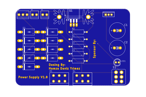
 Hamza Deniz Yılmaz
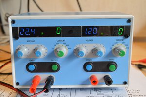
 w_k_fay