 Attila Sukosd
What is this Micro Drone 3.0 you refer to?
Indiegogo project about making a small, fun, customizable drone:
https://www.indiegogo.com/projects/micro-drone-3-0-flight-in-the-palm-of-your-hand--2#/
Why are you working on this project?
- It's fun, and I'm fascinated with robotics, vehicles and especially stuff that flies.
- I like to know what's going on "behind the scenes"
- I would like to learn more about control theory and what it takes to make something stay in the air
- Customize and improve the product, work on the shortcomings of the product
- I would like to have a drone that I can use for areal photography, where I don't have to worry so much about the controls, but more about getting the shot, but also not spend thousands of dollars on a drone.
Why the MD3.0 instead of *insert random other drone*?
- It's affordable (not too cheap, but also not $1000+ beast)
- It's safe(r) than bigger drones: I'm a noob drone flier, so I'd rather have this one fall out of the sky than a bigger model
- It's reasonable quality
- It's powerful enough to carry some (very) small payload
What are the shortcomings of the MD3.0?
- It lacks sensory inputs for more "high end" features like altitude hold, gps lock, etc
- The firmware is closed source, so it can't be tweaked
What kind of mods are you thinking about?
- Alternate (open source) firmware, which would enable more features (fx. acro mode)
- Add a compass + barometer for it to know heading + altitude
- Upgrade the 720p@30fps camera to a 1080p@30-60p with an ultra wide angle lense (110+ degrees)

 Xasin
Xasin
 Alex Brown
 MakersBox
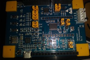
 Ian Shannon Weber
You are hacking the main PCB board, but it is also possible to go from the other side (from the camera module and Android/iPhone app). You may find something useful at: http://gw.tnode.com/drone/micro-drone-3-0-camera-api/