Robot Electrical
- Potentiometers (acting as position sensor) 0 - 300 ohms
- Motor Current 0.2A and 1A stall
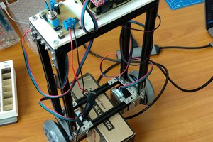
Using new technology to bring an old 4 axis DC robotic arm back to life
Already have an account? Log in.
To make the experience fit your profile, pick a username and tell us what interests you.
 Sergey Royz
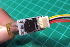
 Danny FR
 Charles Galambos
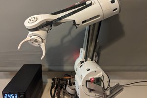
 Petar Crnjak