 Petar Crnjak
Find out more at: https://source-robotics.com/
Join forum: https://discourse.source-robotics.com
Join discord: https://discord.gg/prjUvjmGpZ
The Problem
Today every engineer, maker, and tinkerer can get access to a decent 3D printer for less than 300$ and start creating. Many of those people that have 3D printers also want to play and experiment with robotic arms that are close to the size or performance of human arms. While industrial robotic arms are too expensive, the only alternative is DIY robotic arms that are in most cases not really easy to program or capable of doing useful tasks.
Also, the DIY arm that will be used at home or near other people needs to be safe. That can be hard if using large reduction gearboxes or building a robotic arm that weighs a lot.
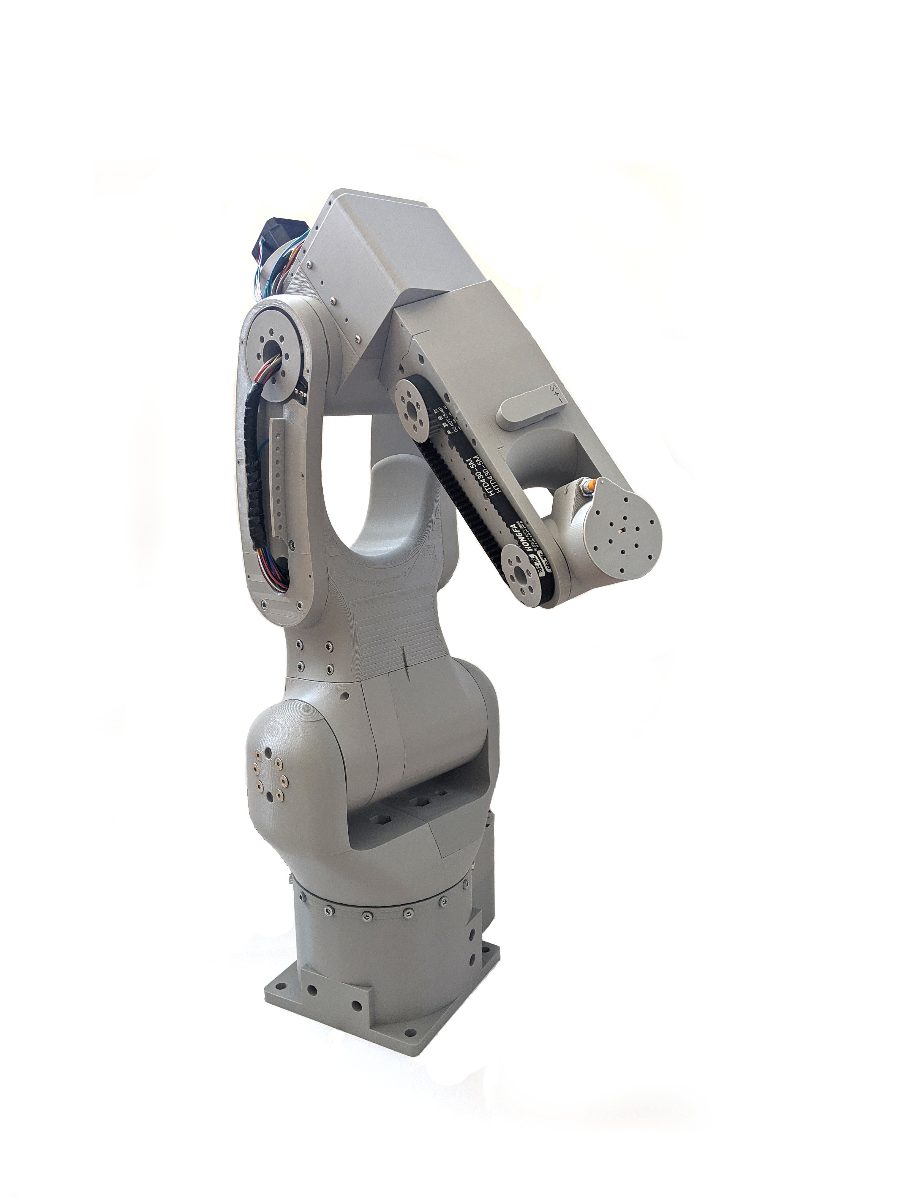
The Solution
CM6 is a robotic arm that could fill that gap. It is safe, compliant, and most of all cheap. CM6 is a 3D printable COBOT robotic arm that uses QDD (Quasi direct drive actuators). QDD gives CM6 passive compliance which makes it behave like a human arm.
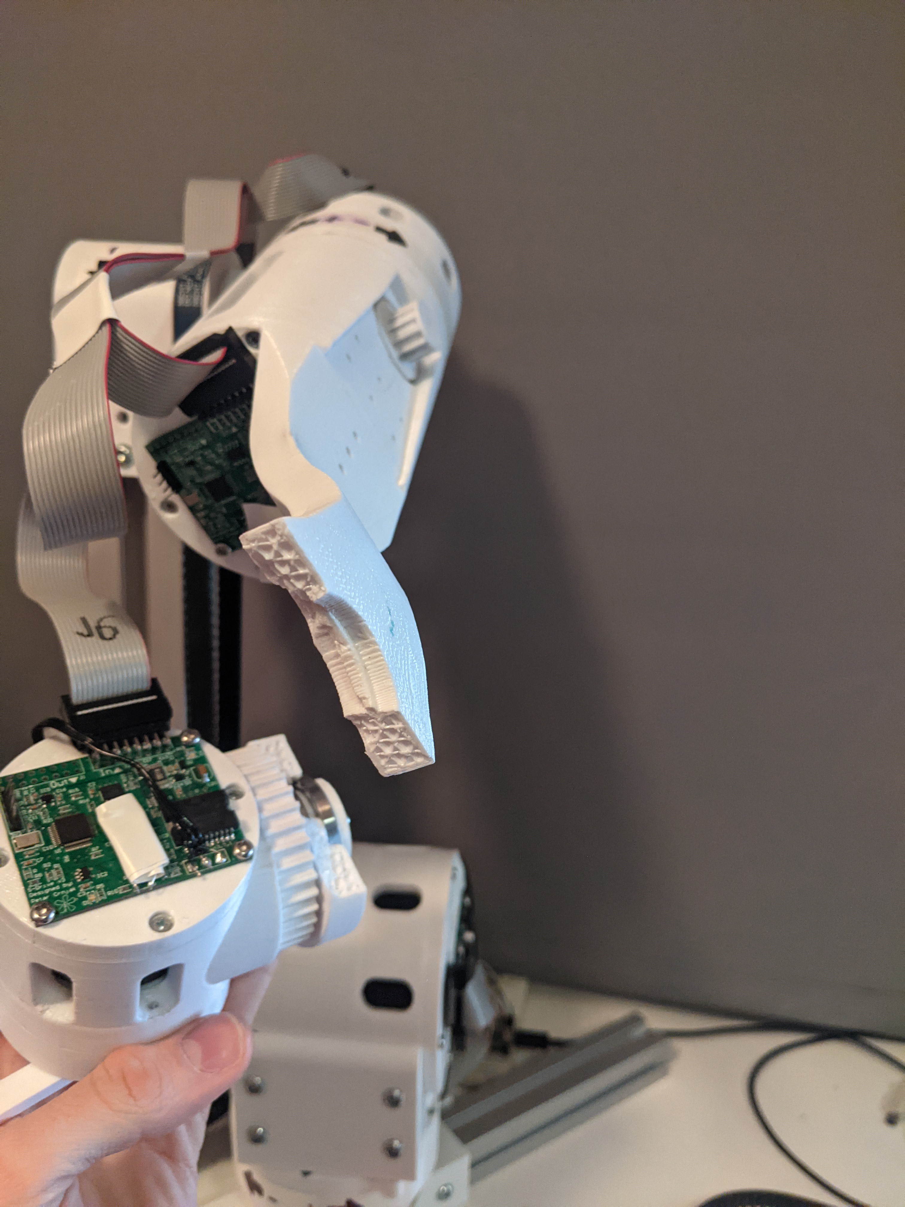
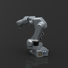
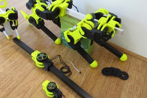
Actuators
Actuators of choice for CM6 unlike most DIY robotic arms are BLDC gimbal motors. Also, this robot arm uses small reduction gearboxes (from 5:1- 9:1). These two aspects are what make this arm different from other arms. The inherited high torque and low-speed operation of BLDC gimbal motors allow great responsiveness to external disturbances and accurate current measurement. Paired with a small reduction gearbox to increase the torque a bit but still keep those great aspects of BLDC are crucial to the operation of this arm.
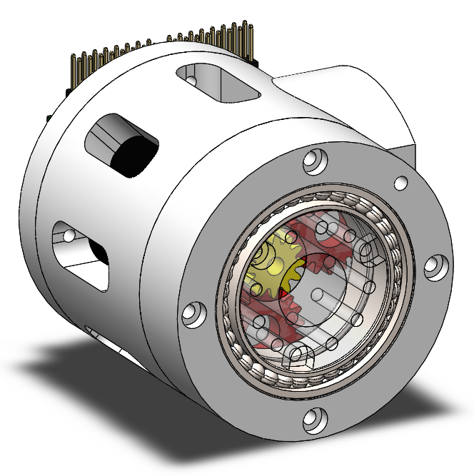
All actuators of this robot are 3d printed planetary gearboxes with single-stage reduction. They are designed to be easy to print, compact and most of all modular. With just a few changes in design, you can get a smaller / larger reduction or even add another reduction stage.
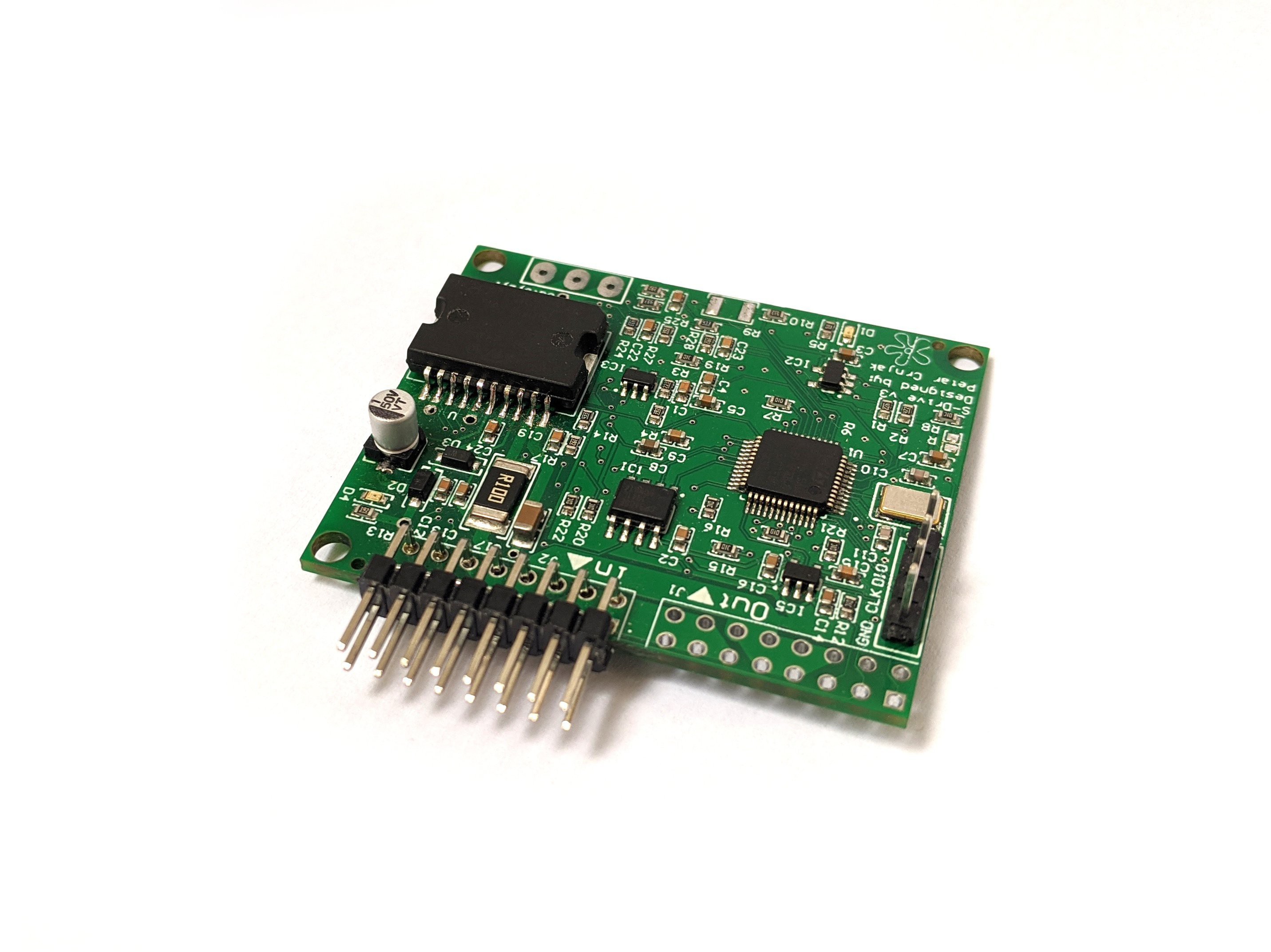
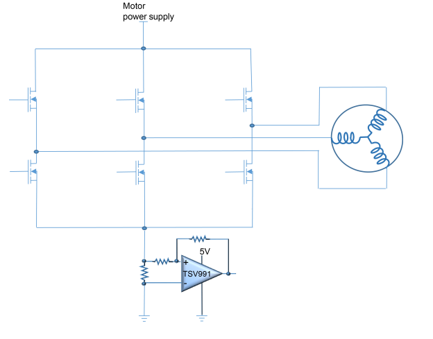
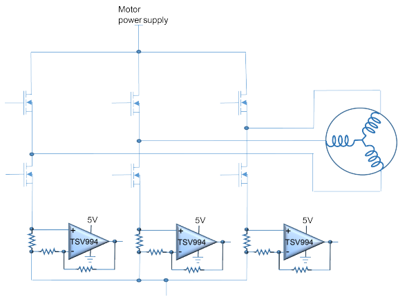
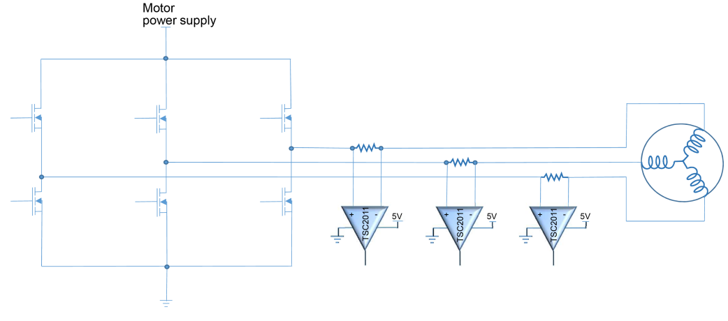
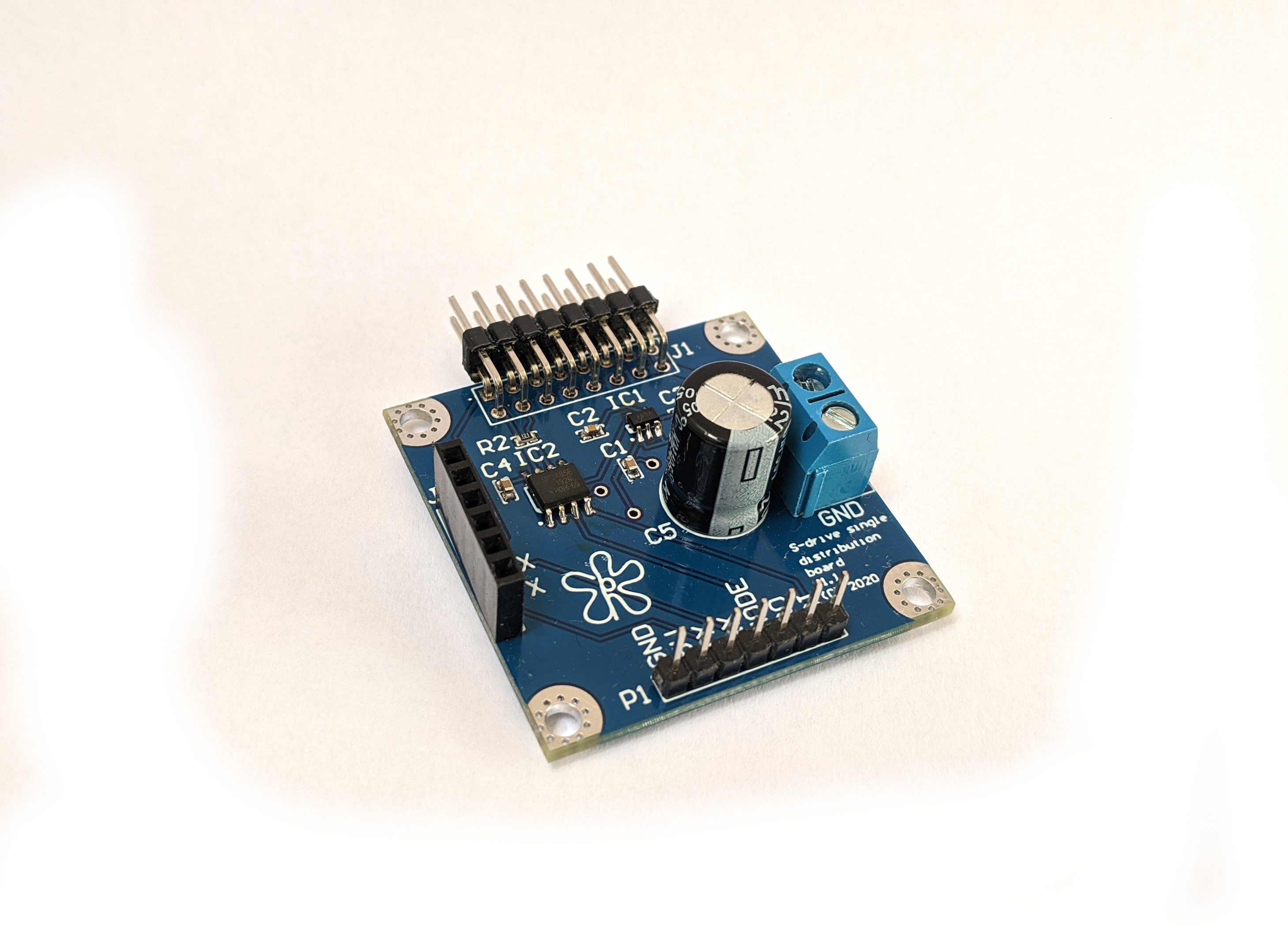
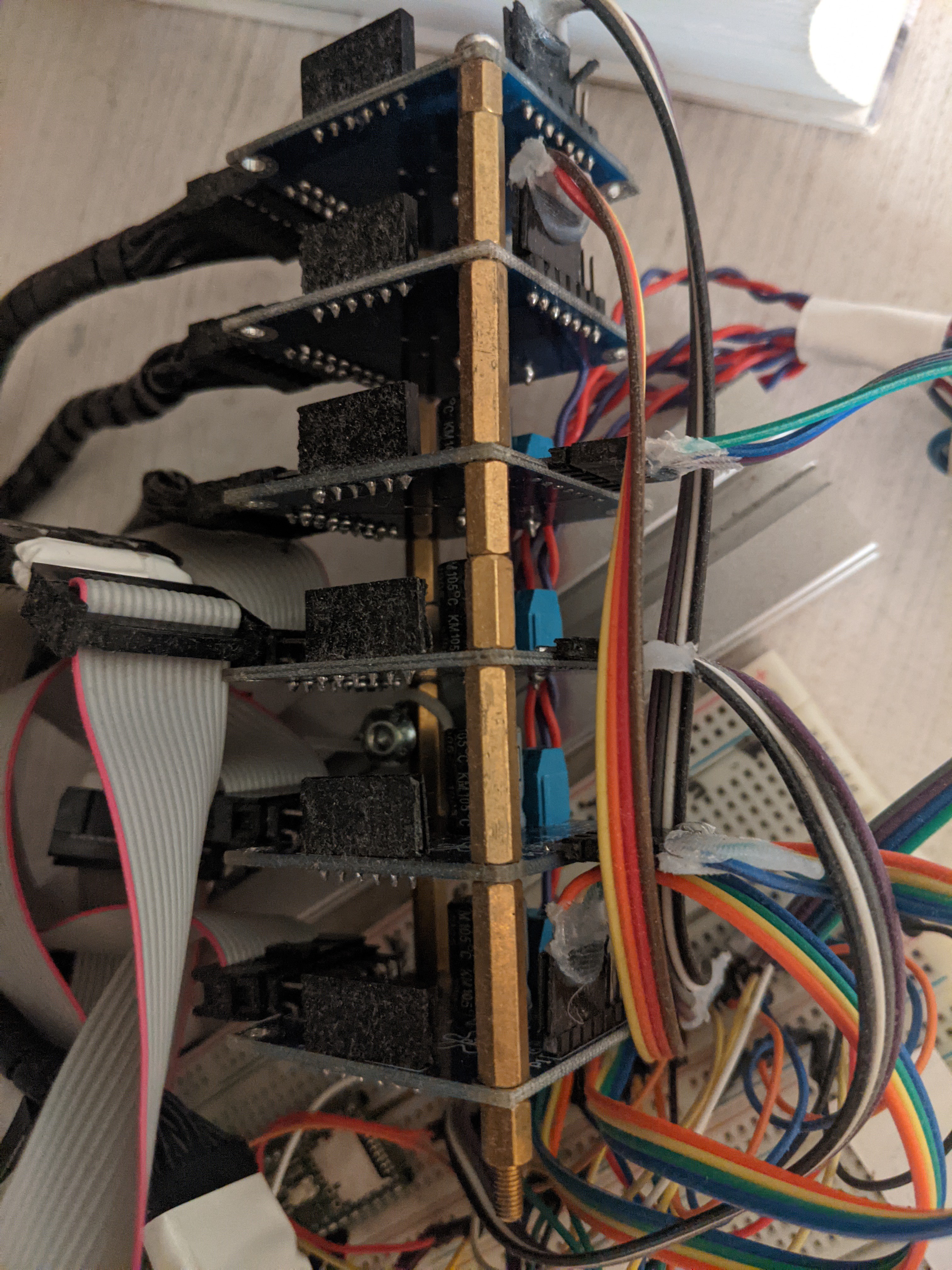
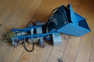
BLDC drivers
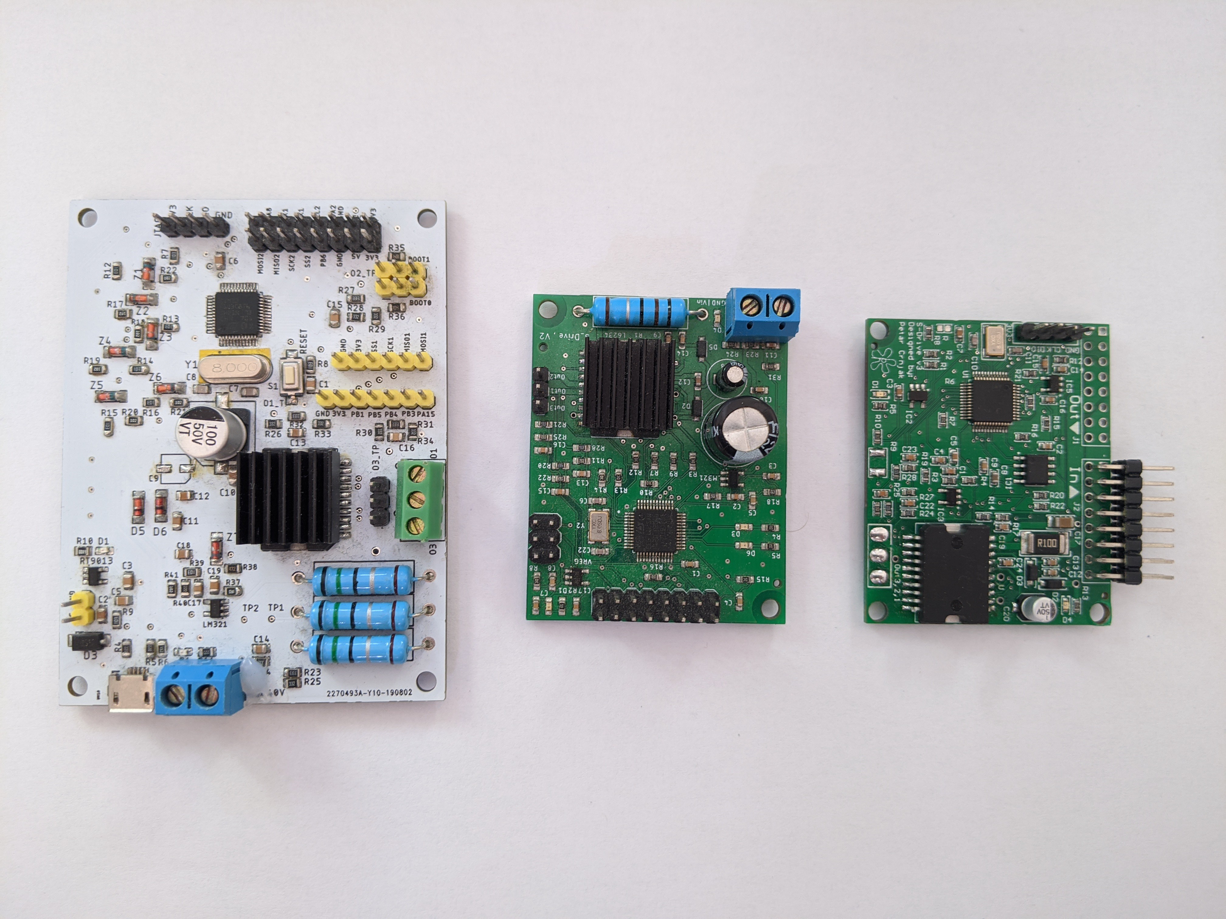
BLDC drivers are custom-made and are called S-Drive (Small drive). In the picture above you can see the evolution of the design, with the right one being the newest one. The goal of these drivers was to use the smallest amount of components possible and to keep the price low.
Key features of the driver are:
- L6234 Three-phase motor driver
- AS5040 10 bit encoder
- stm32f103c ARM M3 microcontroller
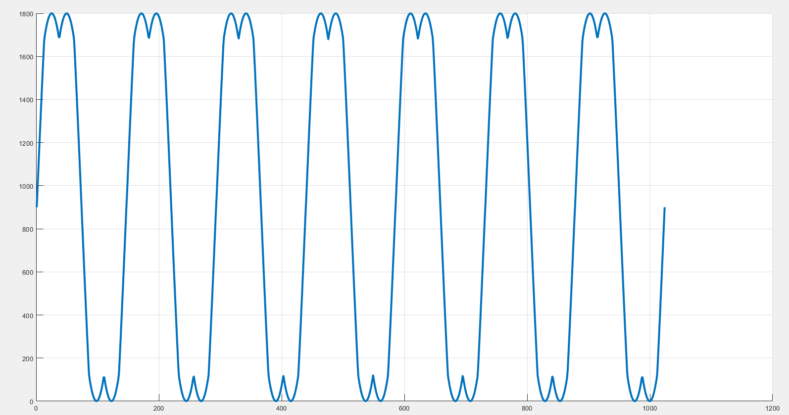
- global low side current sensing
- UART and RS485 comms
More info on the driver: Hackaday page! Github page with firmware or DOCS.
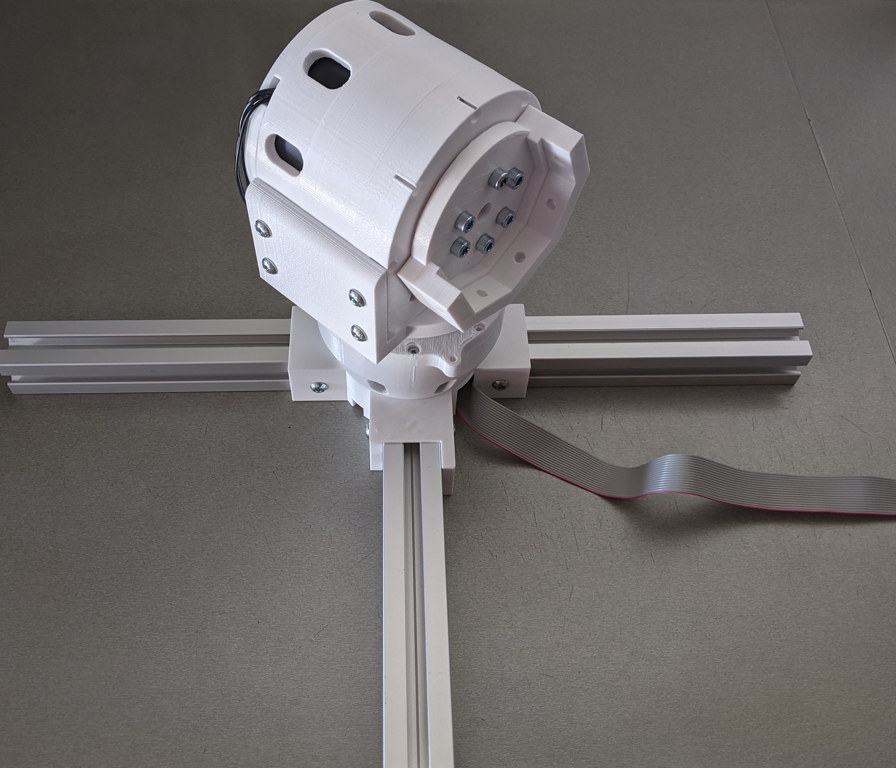
Lightweight mechanical design
The whole robot (including base holders) weighs less than 5kg. This is achieved by using aluminum profiles to connect parts and using low infill PETG 3d printed parts.
Easy to use software
Another important part of this project was to have software that makes programing robots "easy". GUI software was written in python and heavily relies on Petar Corke's robotic toolbox for python! It was tested on Linux virtual machine, laptop running Linux, and raspberry pi 4!
The software offers real-time monitoring of robots:
- Motor position, current, speed, temperature
- End effector position
- Operating modes, errors...
Available modes at this moment are:
- Individual motor jogging
- freehand teach
- move from point to point
Each of these modes of movement can be recorded and replayed!
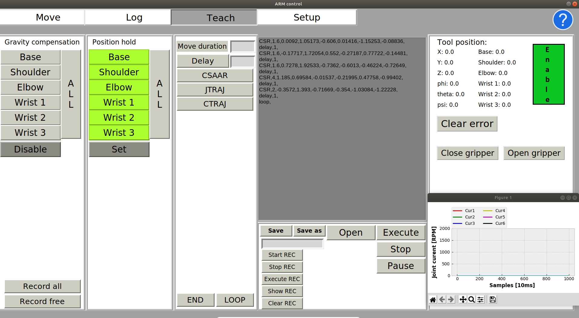
- This is an image of Teach menu. Here you can program your robot by writing code in "gray window" or by freehand movements.
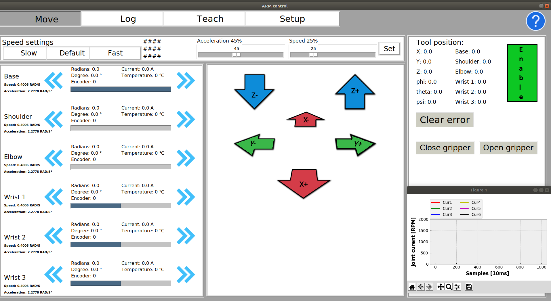
- This is Move menu of the GUI. It allows you to jog individual motors and in the near future jog robot by XYZ.
Operation
Specs
- Weight: 5kg
- Reach:
- repeatability: +- 0.5mm (Needs visual servoing like human arms to be really precise)
- Max load: 3kg (limited reach)
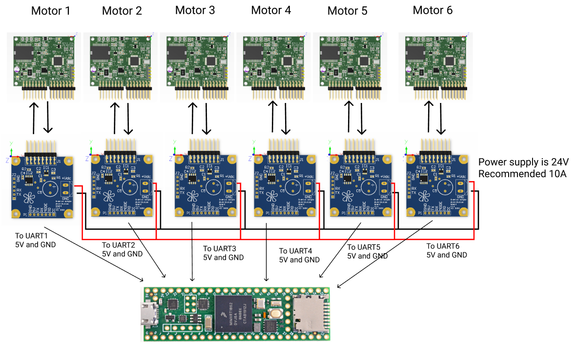
- Voltage: 24V
- Max motor current: 5A (limited by the motor driver)
- Power supply power: recommended 24V/10A


 Paul Gould
 f4hdk
f4hdk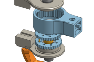
 Tim Wilkinson
The first video in the project description is private. Nobody but you can watch it.