0%
0%
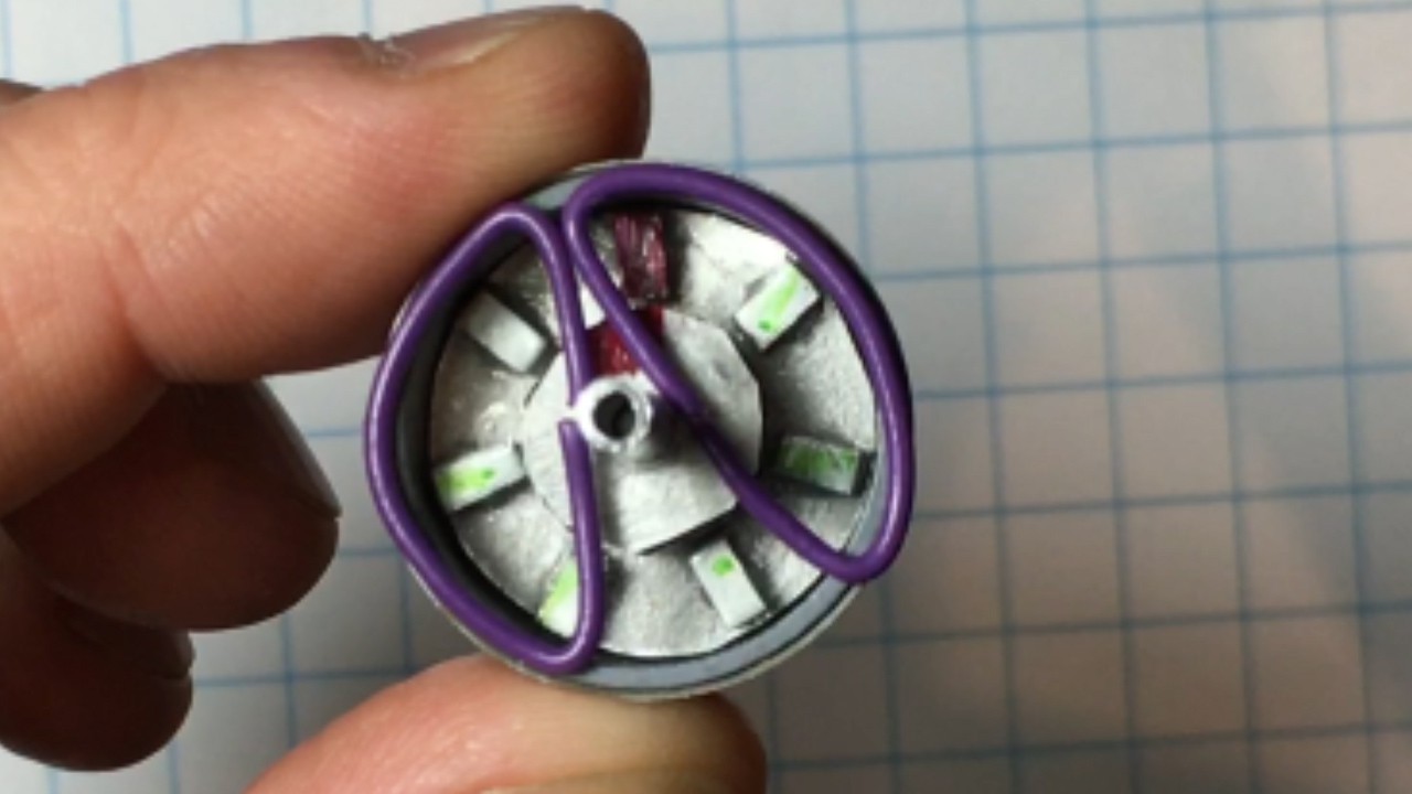
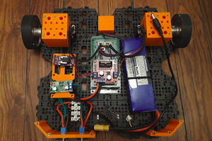
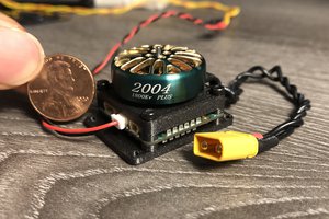
3D Printed Robot Actuator
A high speed and high torque robotic actuator using low-cost brushless motors, custom controller, 3D printed parts and bearings.
 Paul Gould
Become a Hackaday.io member
Already have an account? Log in.
Just one more thing
To make the experience fit your profile, pick a username and tell us what interests you.
Pick an awesome username
hackaday.io/
Your profile's URL: hackaday.io/username. Max 25 alphanumeric characters.
Pick a few interests
Projects that share your interests
People that share your interests


 matop
matop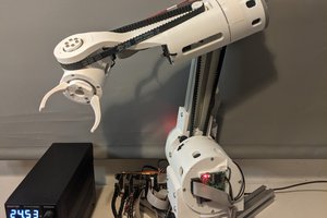
 Petar Crnjak
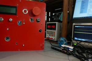
 Christopher Xu
Hi Paul, I sent a note to the application. i need to have some targeted iimprovement on this design for prosthetic elbow design. i am a father a child who needs one, i need to work or get some work done on this specific design idea.. thank you