 matop
matopWhy this project ?
It makes no doubt that ROS (Robot Operating System) is the most common framework for robotics. It offers a powerful middleware for interconnecting sensors and actuators with already packaged drivers and state-of-the-art algorithms (SLAM, vision based algos, IA, control...) also already packaged by the huge open source community.
Among the countless robotics projects based on ROS, one of them shine by its number of features and its rich documentation and tutorials: the famous TurtleBot3. Its open source hardware with modular mechanics is the base for variety of robot's type: 2 Wheel-Drive, 4WD, 6WD, omnidirectional wheels, embedded robotic arm:
http://emanual.robotis.com/docs/en/platform/turtlebot3/features/#worlds-most-popular-ros-platform
NB: Although this project is oriented on turtlebot's like robot, those features could be used for any robotics platform of your mind
Current Architecture
Hardware components on the Waffle TB3 and Burger TB3 (2WD) are listed above:
- Propulsion Motors: Dynamixel XM430 servomotor (expensive). Dynamixel servomotors are high quality and performance servomotors, offering advanced features like torque, rate and position control with a complete SDK. All hose features are not needed and came at a price.
- Microcontroller running low level task: OpenCR board based on Cortex M7 (expensive). This board delivers power for all components, it integrates an IMU sensor, different communication and I/O ports
- Single Board Computer (SBC) running high level task: RaspberryPi (affordable)
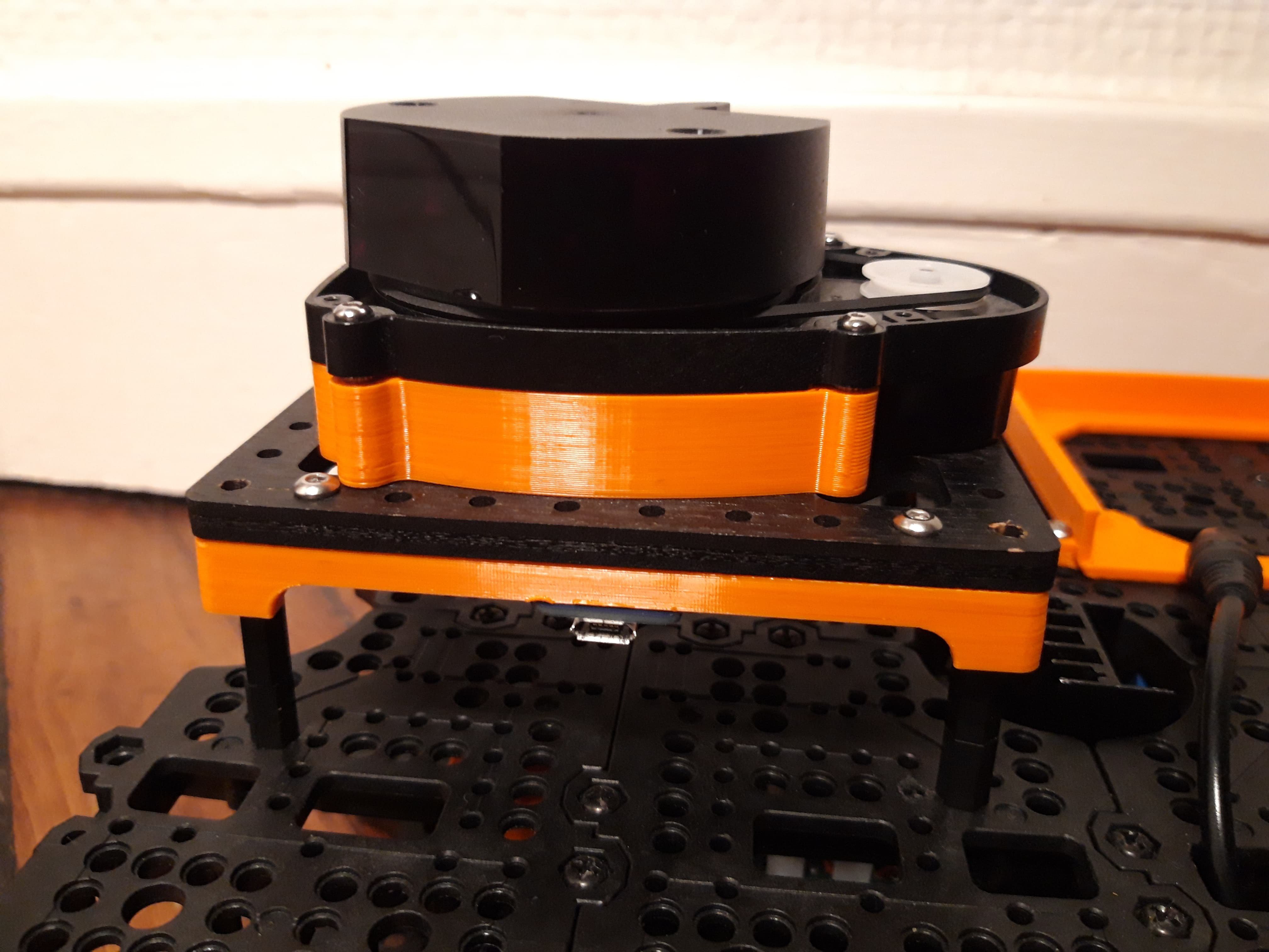
- Sensors: LIDAR, cameras (affordable)
Goal
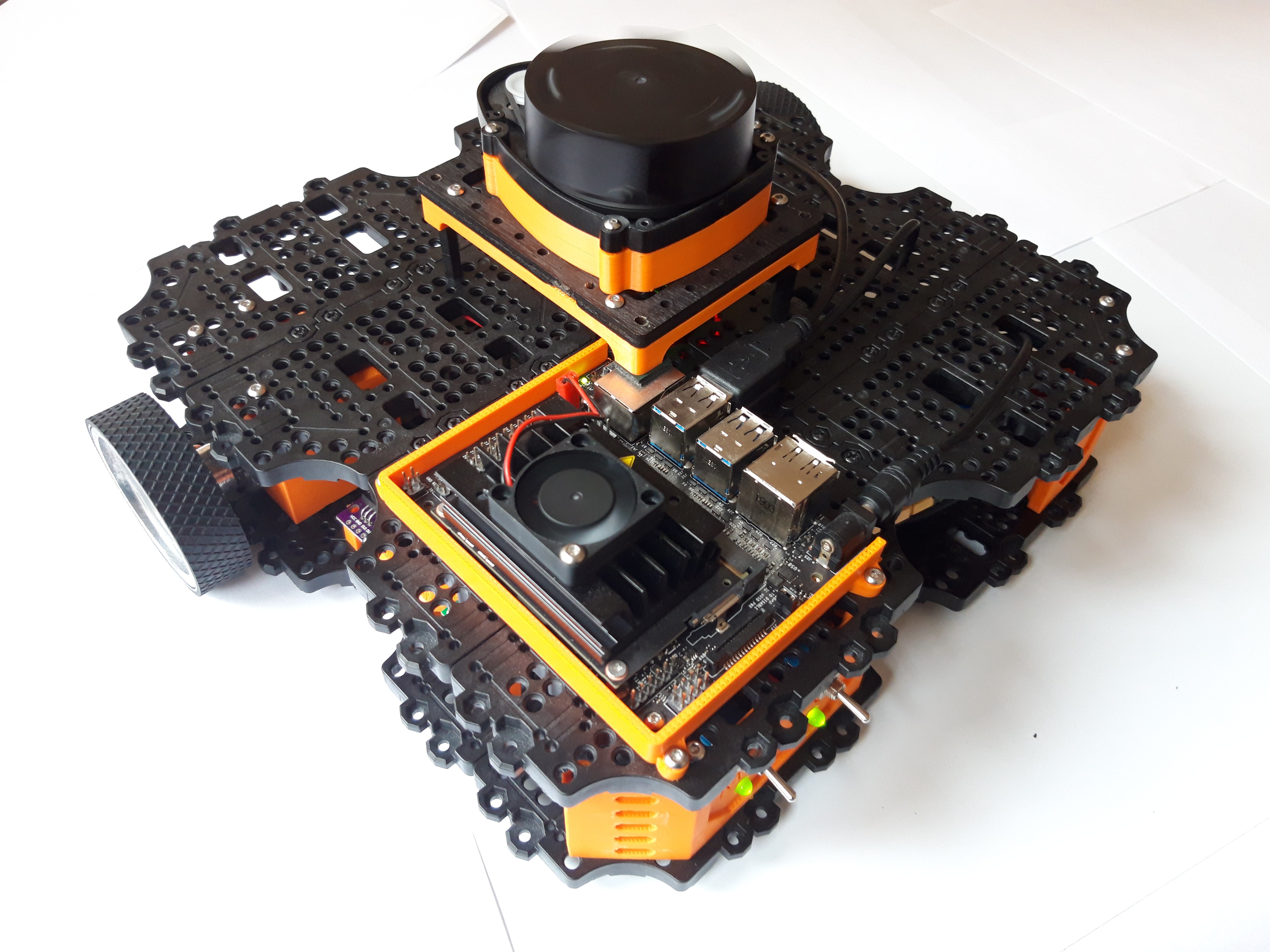
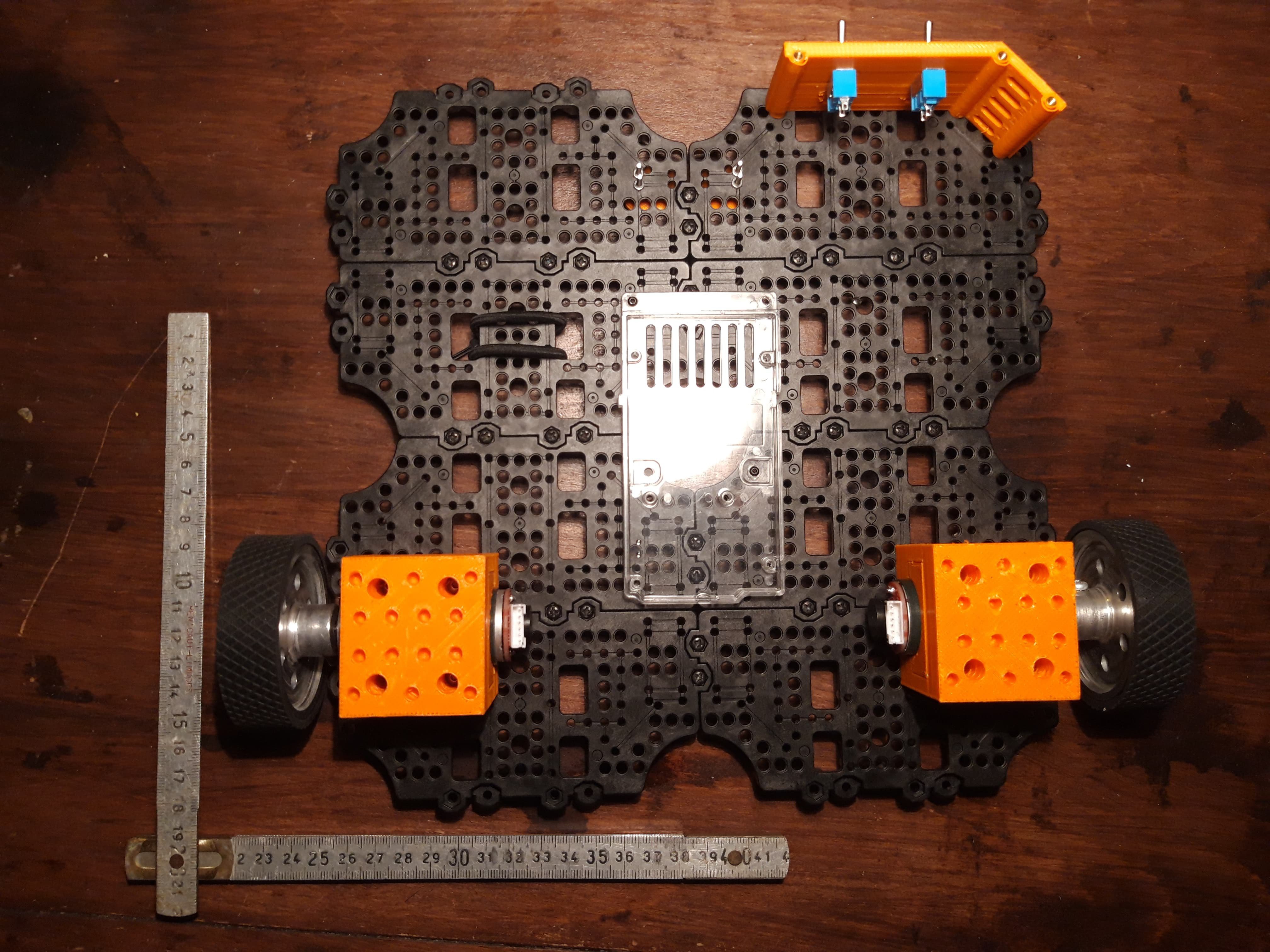
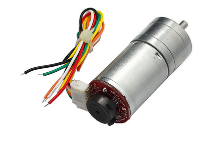
This project aims at replacing expensive hardware components with cheaper ones, while keeping software compatibility. Thus Dynamixel servos with OpenCR board will be respectively replaced by brushed DC motors with Arduino Due (based on Cortex M3). The microcontroller firmware will be adapted to match modified hardware.
In order to run high level tasks such as SLAM or vision based algorithms, the Rapsberry Pi is replaced by the Jetson Nano.
Features
In this section, I will update the developing state of features covered by Dynamixel+OpenCR converted into BrushedDC+Due.
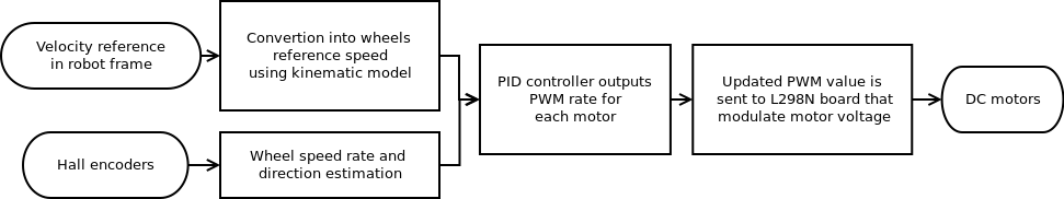
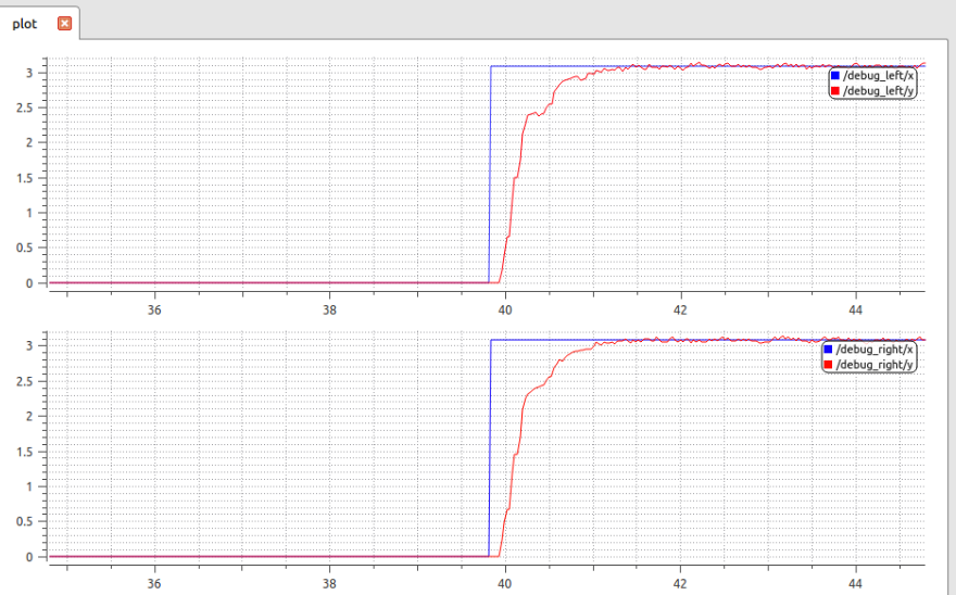
- Motor control: convert velocity commands received from SBC into wheel rates (kinematic model), estimate wheel rate with sensors, perform wheel rate control, distribute power to motors [DONE]
- Odometry publishing: compute odometry from encoders used for localization [DONE]
- IMU publishing: compute unbiased gyro rates and accelerations along with attitude used for localization (current TB3's implementation use biased values) [WIP]
- Robot state publishing: several states indicating battery voltage level, hardware faults [TBD]
Those features constitute the core of the robot and could be seen as turtle's backbone.
Project organization
For this project, i decided to follow an iterative approach: build and develop from lower to higher components while trying to validate each performance individually. Some important points regarding this project:
- this project focuses on TurtleBot3 "backbone" but came in parallel with the design of a complete "TurtleBot3 like" robot
- each feature involves both hardware and software development that will be covered in logs
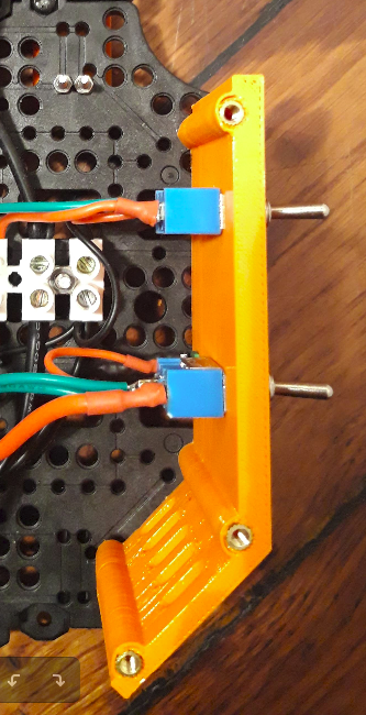
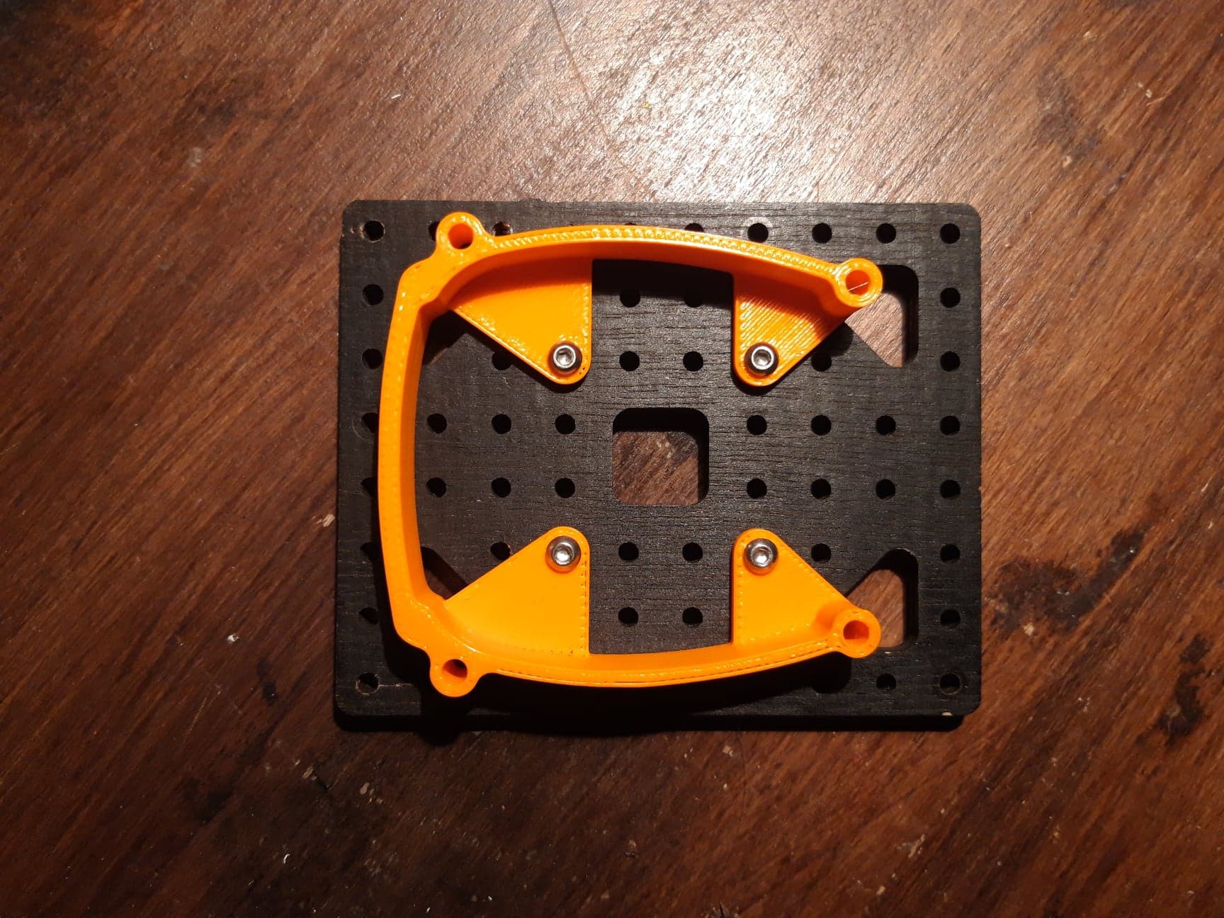
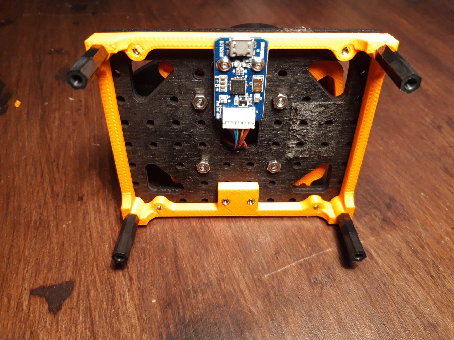
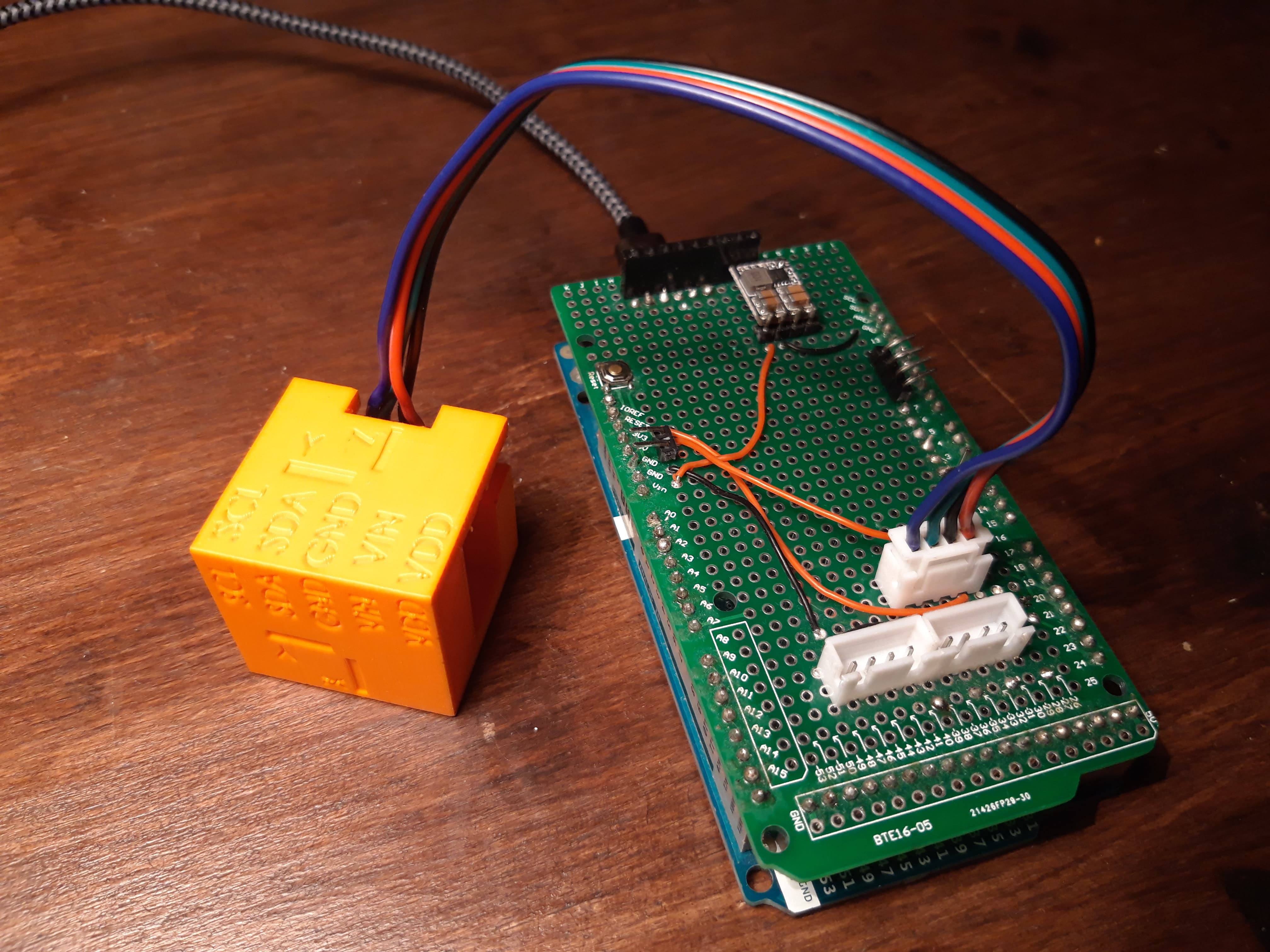
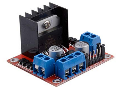
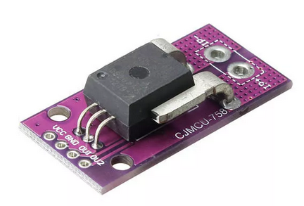
- to facilitate hardware integration, electronics will be simple and based on existing boards (regulators, H bridges, IMU, current sensors...), even if ideally a complete PCB should be designed
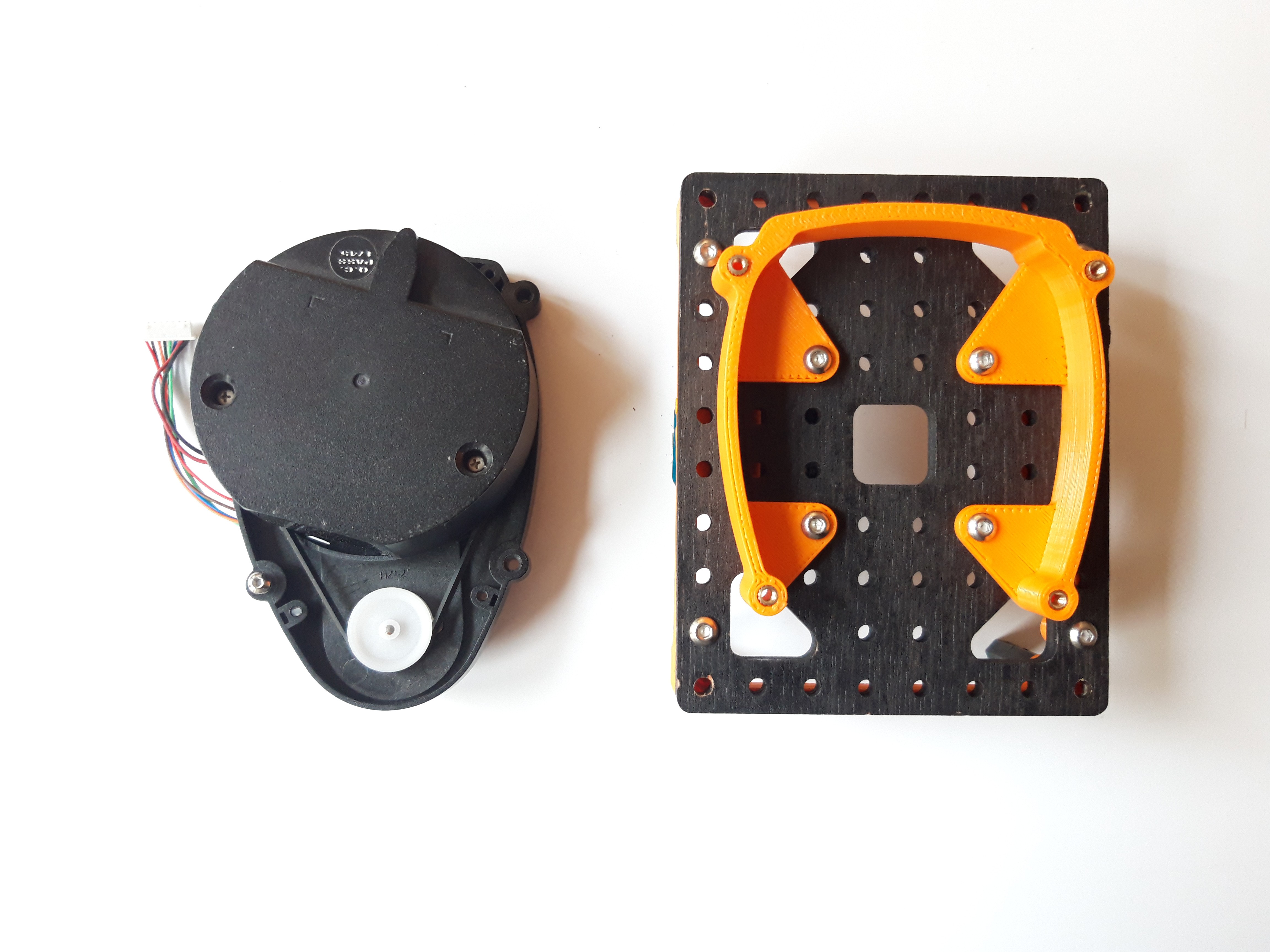
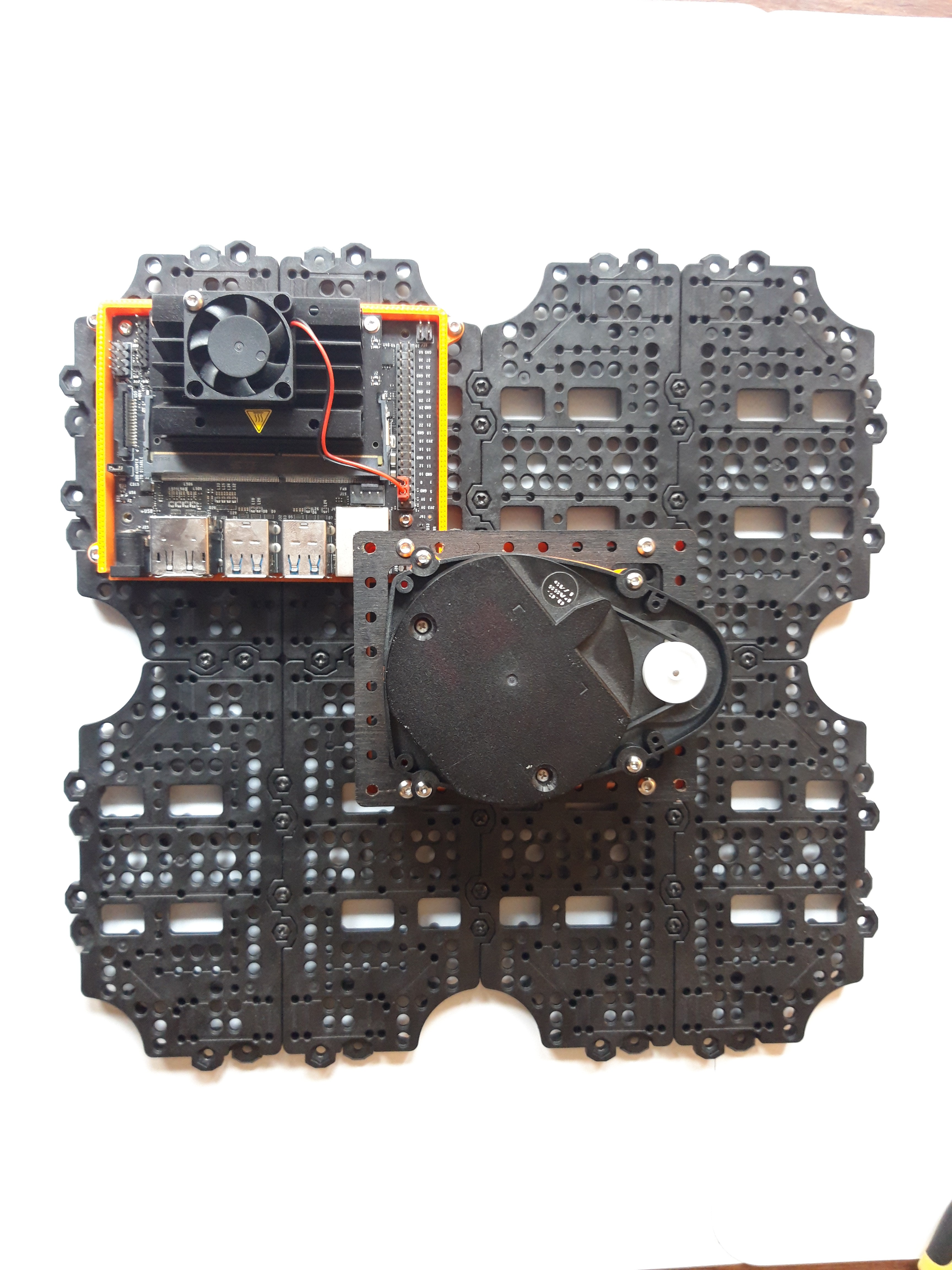
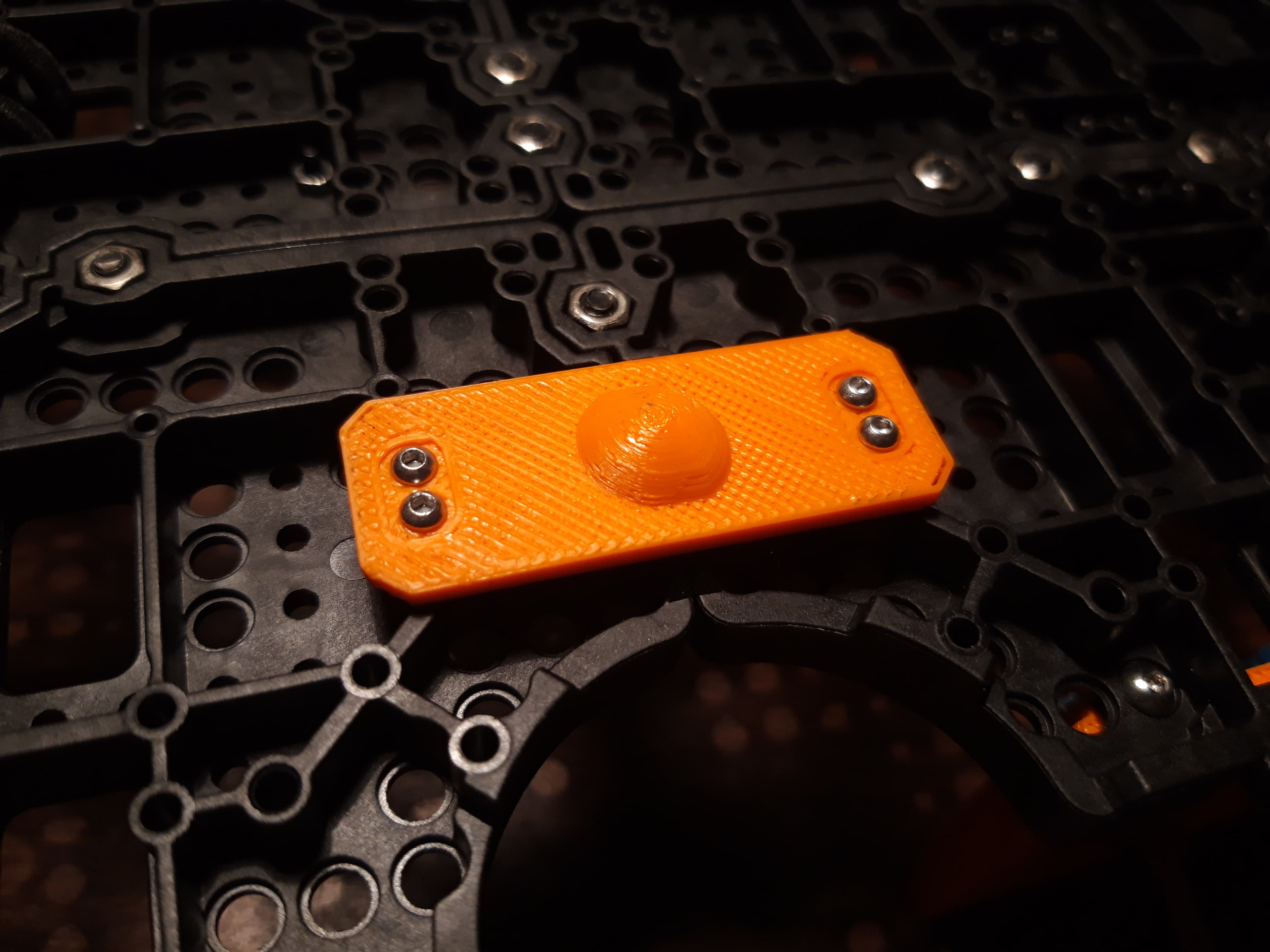
- to validate features a complete platform will be design, based on TB3 base plates proposed by Robotis to reduce mechanical design work


 Petar Crnjak
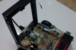
 Simone Tolomei
 Zdenek Hurak
 Paul Gould
Hi! Very impressive project, I am hoping to apply some portions of this project to an Arduino Nano. I believe I am having some issues with the buffer size of the Arduino and the serial rate. I was wondering if you could recommend a possible buffer size for communicating the information from the foxbot_core.io project with the raspberry pi? When attempting to communicate, I receive a notice that 80 bytes where expected but only 19 bytes were received. Thanks!