 sotos.zorbas
Why did I make it?
I am an Electrical and electronics student but as a hobbyist for more than 12 years Ι came across a particular situation lots of times. The thing is that each time I wanted to make a project like a PSU (you never have enough of those …) housed in an aluminum or plastic case I would buy an lcd display. That is a couple of bucks from ebay right? No problem here. Who is going to control the display? An Arduino or an AVR chip programed with Arduino code is usually my first option. The majority of times you want to make measurements and display them on a screen. So you need an ADC, in my experience more accurate than the typical one provided from AVR chip. So you need an external ADC. The same logic applies to the current sensor. Last but not least you want a couple of buttons for signaling purposes. I have yet to found an easy way to mount these things on a front panel without making a huge deal about hole sizes, looks, position etc.
Well, I was sick and tired of this. I mean getting all those parts from different places, calculating resolutions, accuracies every time, spending time making pcb, layout consideration and so much more. So I though what about bringing all those things together into a front panel mounted enclosure?
What makes it special?
The things that makes it special are its features and possibilities.
Features
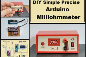
- Microcontroller: ATMEGA328P-AU is the heart of this panel meter. It controls the displays and the led. It checks the buttons states and communicates via I2C with an external ADC.
- ADC: The external ADC can make voltage measurements directly or it can measure the current sensor's voltage using an analog switch (see documentation for details). The ADC has 12 bit (MCP3221) resolution and a very good INL error so in simple terms it is capable to take measurements accurately with calibration. MCP3221 Datasheet
- High Side current sensor: MAX44284 has been chosen for measuring current accurately using a sense resistor in the high side of the circuit. It has a 0-100mV input range (x50 multiplier -> 5V at full scale), so the resistor should be selected from the user to suit his needs. Common voltage range is 0-36V, meaning that the resistor voltage should be in those boundaries at all times. MAX44284 Datasheet
- Accuracy: After calibrating offset and gain errors (See Calibration section below) the total accuracy for both volts and amps measurements is at 0.05% !
What do I mean? It has an ATMEGA328P as I told you earlier. So the user can make it do and display whatever he wants. You can make it work as a clock, you can make it a thermometer, you can use the buttons to make a small menu, you can signal special conditions using the red led, whatever you can think of… I selected the ATMEGA328P-AU to make it directly compatible with Arduino UNO, Nano, micro. It is completely pin compatible with the above Arduino boards. All you need to do is to have an FTDI chip or another Arduino board to program it. Pretty easy. And for those of you who want to program the thing using AVR code they can use the ISP header instead. Is that all? No!
What else?Think for a second, it uses a microcontroller right? So it would be stupid not telling you that there are a couple of unused pins, ISP, I2C, and Serial headers for the user. So you can take measurements and send them to another microcontroller using a protocol from above. You can send stuff to PC, you can buy an IO expander chip for a couple of bucks, connect it via I2C/SPI and get the whole project up and running using the Panel Meter’s microcontroller!!
Quality, assembly, calibration
- All electronic parts are bought from Mouser or TME. It would be possible to save off a few bucks from the final price using ebay and other non-verified source but it isn’t worth it.
- All products are already assembled and calibrated individually verifying proper functionality and meeting all specs.
- Calibration: All offset- gain errors are measured and you get a note with...


 mircemk
 jaromir.sukuba
Yes of course, at the project description is your answer . Just visit my Tindie page linked here and everything is there already.