Close
0%
0%

HeadsUp, a Low-Cost Device to Diagnose Concussions

Diagnose potential traumatic brain injuries on the sidelines quickly, cheaply, and conveniently using a 30-second eye test.

Similar projects worth following

Inspiration

Concussions suck—we're both high school students, and we've had many friends struggle through the aftermath of receiving one though a school sport or an unfortunate circumstance. However, one may almost say they're lucky, as they were people who figured out the had concussions and were able to have them treated. Almost half of all athletes don't report feeling symptoms after receiving a concussive blow, and a total of 1.6-3.8 million concussions occur in the United States every year (estimated by the CDC).

In order to address the major problem of undiagnosed and unreported concussions in youth sports, adult sports, and the mayhem of everyday life, we realized that a better system was needed—one that could be close and accessible, affordable for all teams, and easy to use.

What it does

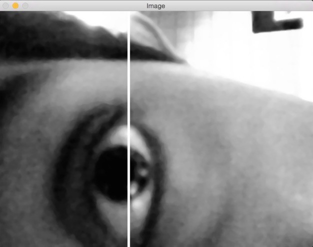
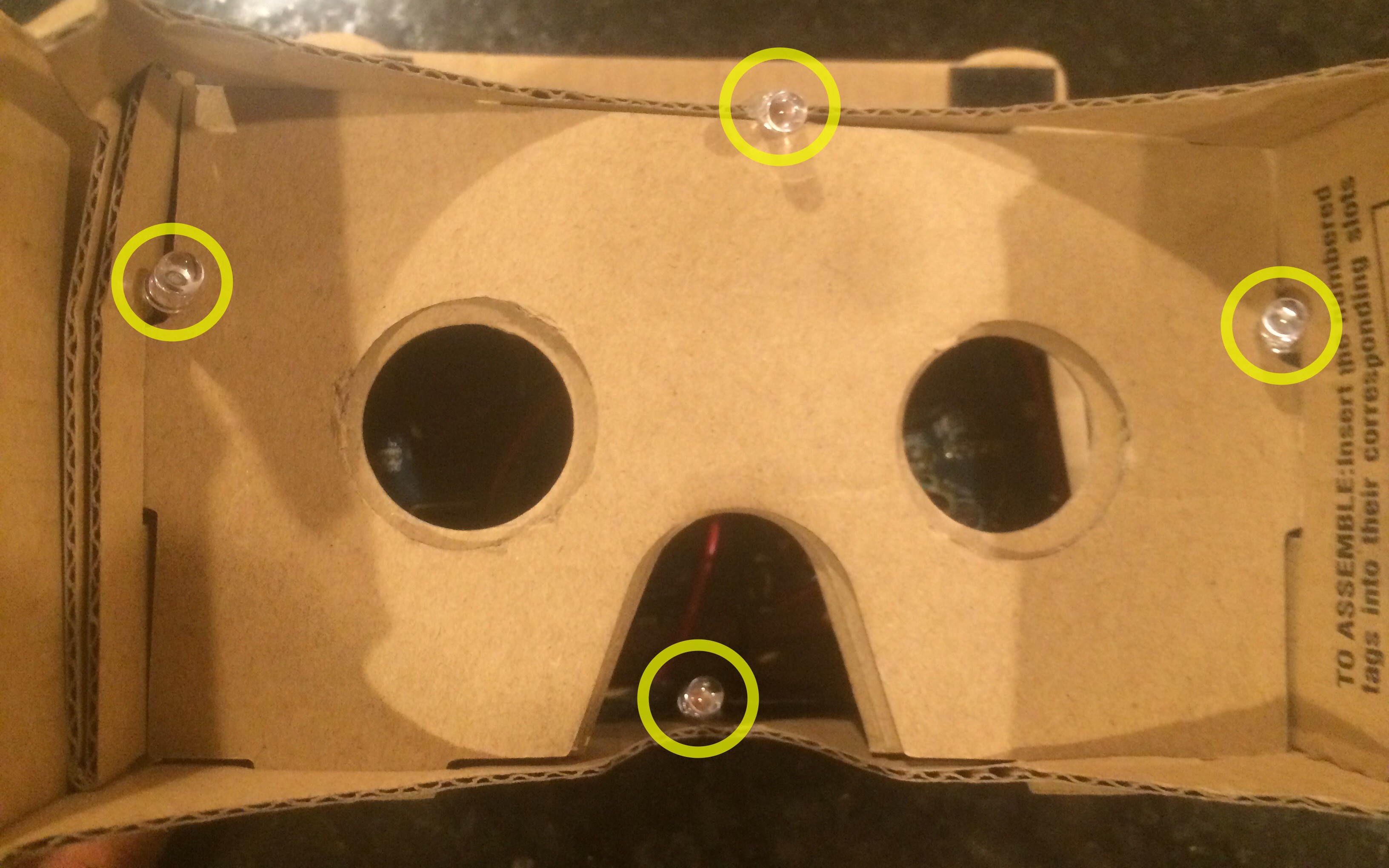
HeadsUp uses a common diagnostic methodology, the tracking of patient's eye movements in response to stimuli. The difference between HeadsUp and the cheapest hospital equipment? Cost. Commercial hospital equipment runs $5,000 at minimum, and can run up to $25,000, which means HeadsUp is hundreds of times cheaper.

View all 16 components

  • Finished Electronics for New Prototype

    Mihir Garimella07/11/2016 at 09:10 0 comments

    We just printed the new enclosure, so we needed to add some electronics to complete our prototype. We worked on the electronics in segments based on what part of the enclosure they were in.

    For the top, we cut an LED strip into five pieces to fit each of the five raised platforms. We then wired the pieces together and hot glued each to the corresponding raised platform on the printed enclosure.

    For the middle, we stripped the casing off the PS3Eye cameras. We cut off the two status LED's on the bottom and the five microphones on the top for each camera. We also desoldered each camera's USB cable and soldered a four-pin cable instead.

    Finally, for the bottom, we used a pair of flush cutters to remove one set of USB ports on the Raspberry Pi. We then soldered a four-pin header in the place of each USB port and connected the four-pin cables from the cameras.

  • Finished 3D Printing New Enclosure

    Mihir Garimella07/11/2016 at 07:21 0 comments

    It took around 28 hours, but we finally finished printing the parts on our school's Makerbot! Here are the parts right after we took them off of the printer:

    After removing rafts and support material, we discovered a minor problem: we had put tape over the build platform to make removing the parts easier, but the tape was pretty uneven and as a result our parts weren't flat.

    They should still be okay, since we can secure the pieces together very tightly on the flat sides to make the entire enclosure squared. The next step is to verify that the components fit properly inside the enclosure, add the electronics, and put the prototype together—more on that soon!

  • Made CAD Models for New Prototype Enclosure

    Mihir Garimella07/11/2016 at 07:20 0 comments

    Although our hackathon project was a great proof of concept, we needed to make several improvements to get closer to a final product. One improvement that we thought of was a new enclosure: our hackathon prototype was literally made out of cardboard and glue, which worked well in a time-limited environment but wasn't very robust. For example, the camera mount wasn't attached to the actual body of the Google Cardboard, so it needed to be positioned properly before each use to ensure accurate eye tracking. Also, a new enclosure would be the starting point for a new prototype, as a new enclosure would afford us significantly more flexibility in design (e.g., we could replace the external computer that ran the eye tracking code offline with an onboard embedded platform that would perform the vision tasks in real-time).

    We thought about what our enclosure should look like and we ended up splitting it into three discrete parts: the top, which would contain the LED's to show the user a visual pattern; the middle, which would hold the two cameras for eye tracking; and the bottom, which would hold the Raspberry Pi and other circuitry. Next, we modeled each part in Google Sketchup, with a particular focus on making the parts easily printable with minimal support material.

    Here's the top:

    We used the original Google Cardboard drawings to model the forehead and nose cutouts and the eye holes. Next, we added raised platforms around the edges for LED strips, which we thought would be much cleaner than individual LED's. We added small holes next to each LED strip (except the one on the bottom left, where the strip starts) to contain the wire used to chain the strips together. Also, we added four M3 screw holes around the sides to attach the top piece to the middle.

    Here's the middle:

    Again, we used the original Cardboard drawing to model the nose cutout on the bottom. We added a slot in the middle for the battery and several M2 screw holes on each side for the PS3Eye cameras (positioned based on measurements on the camera circuit boards carefully taken by hand). We cut out the material behind the cameras to provide room for the cables to pass through. We also added M3 screw holes around the sides on both the top and bottom, to attach the middle to the other parts.

    Here's the bottom:

    We added M3 standoffs to attach the Raspberry Pi (two aren't pictured). We also added cutouts for the Raspberry Pi's ports (minus one set of USB ports on the top to which we were directly going to attach the cameras). In addition, we added a small raised platform on the top for a voltage regulator, with a cutout in the top left corner of the enclosure for the battery cable to pass through. Finally, we added M3 screw holes around the sides to attach this module to the middle.

    (You can access all of these CAD models from the Dropbox link in the sidebar.)

  • Writing Software to Track Eye Movements

    Mihir Garimella07/11/2016 at 06:06 0 comments

    Now that we had some hardware to work with, we needed to write software to track a user's eyes while we showed them a visual pattern.

    The second half of this—displaying a pattern on the LED's attached to the Spark Core—was the easy part, so we did that first. We created a cloud-connected Spark.function called "start" that would turn the bottom, left, top, and right LED's on for six seconds each (in that order). Then, whenever we needed to start displaying the pattern, we used cURL to call the function over the Spark Cloud. This was all really simple, and accomplished in ~50 lines of code.

    The next step was actually tracking a user's eye movements. We brainstormed methods and prototyped them in OpenCV. For example, an early implementation found the x-coordinate with maximum contrast (going from the white part of the eye to the iris/pupil and back to the white part) to locate the pupil horizontally, and then found the darkest cluster of pixels along that x-coordinate to find the center of the pupil vertically. Here's a photo after the program found the horizontal position of the pupil:

    We also tried a few open-source implementations, like this one. However, we found that none of these methods were robust; one particularly difficult problem was when the user was looking almost straight down at the LED on the bottom of the device; their eyelid would be covering most of their eye, so only a small, non-circular portion of the iris would be visible.

    We kept thinking and ultimately came up with the algorithm that we ended up demoing at PennApps. We first passed each camera image through one of OpenCV's Haar cascade classifiers to isolate the eye and remove the rest of the face. Then, along the vertical line at the horizontal center of the eye image, we found the number of white pixels before and after the darkest cluster of pixels, and we repeated this procedure along the horizontal line at the vertical center. Then, we compared the number of white pixels on either side of the dark cluster for both directions to determine the direction of the user's gaze. For example, if the amount of white pixels on the right side of the iris was far smaller than the number of white pixels on the left side of the iris, then the user was most likely looking to the right.

    We implemented the final algorithm in C++. We couldn't run it in real-time because we weren't able to find a PS3Eye driver for Mac that allowed us to read the cameras from OpenCV, so used an open-source viewer app to display the PS3Eye camera feeds on screen, used QuickTime to make a screen recording, and passed the resulting movie through our eye tracking program. Instructions for testing this out (along with a recording that we made during testing) can be found in the readme of our Github repository.

    (In our next prototype, we definitely plan to modify our approach to be able to perform the eye tracking and diagnosis in real-time).

  • Building a First Prototype

    Mihir Garimella06/21/2016 at 05:37 0 comments

    After pivoting to a device that could diagnose concussions, we needed to build some hardware to get our idea off the ground—and fast! We knew that we needed to track a user's eye movements while we showed them some sort of visual pattern, so we looked around at the materials we had. For the AR hack that we had initially planned to build, we had a Google Cardboard and four Playstation Eye cameras (dirt-cheap, 120fps VGA-resolution USB cameras), as well as a few components we had lying around—a couple IMU's, a battery, a voltage regulator, stuff like that. We had also signed out a Spark Core microcontroller from the PennApps hardware lab.

    We quickly realized that we could put two of the Playstation cameras inside the Cardboard (where you'd usually put your smartphone) to track eye movements. However, we needed a way to keep them in place, so we designed a simple mount that we could put inside the Cardboard. (Sketch below definitely not to scale.)

    We'd hoped to 3D print this but we missed the deadline to submit CAD models to be printed, so we constructed it ourselves out of a few pieces of cardboard.

    We passed the camera cables through the back of the Cardboard so that they could be easily plugged into a computer.

    Next, we needed to add components to display a visual pattern that the user could follow. We couldn't do anything with a smartphone, because there wasn't any space left inside the Cardboard after we added the cameras, so we decided to use some LED's instead.

    We hot-glued four yellow LED's around the face of the Cardboard...

    ...and wired them up to a piece of prototyping board that we attached between the cameras. We added a socket for the Spark Core on the protoboard, and decided to drive the LED's directly off of four digital I/O pins (since the pins were rated to supply up to 25 mA each). We connected the LED's to Spark pins D3, D4, D5, and D6, with 220Ω resistors in between to limit current.

    Finally, to power the device, we taped a 2-cell LiPo to the side of the Cardboard and connected it to a 5V UBEC, which supplied a steady voltage to the Spark Core.

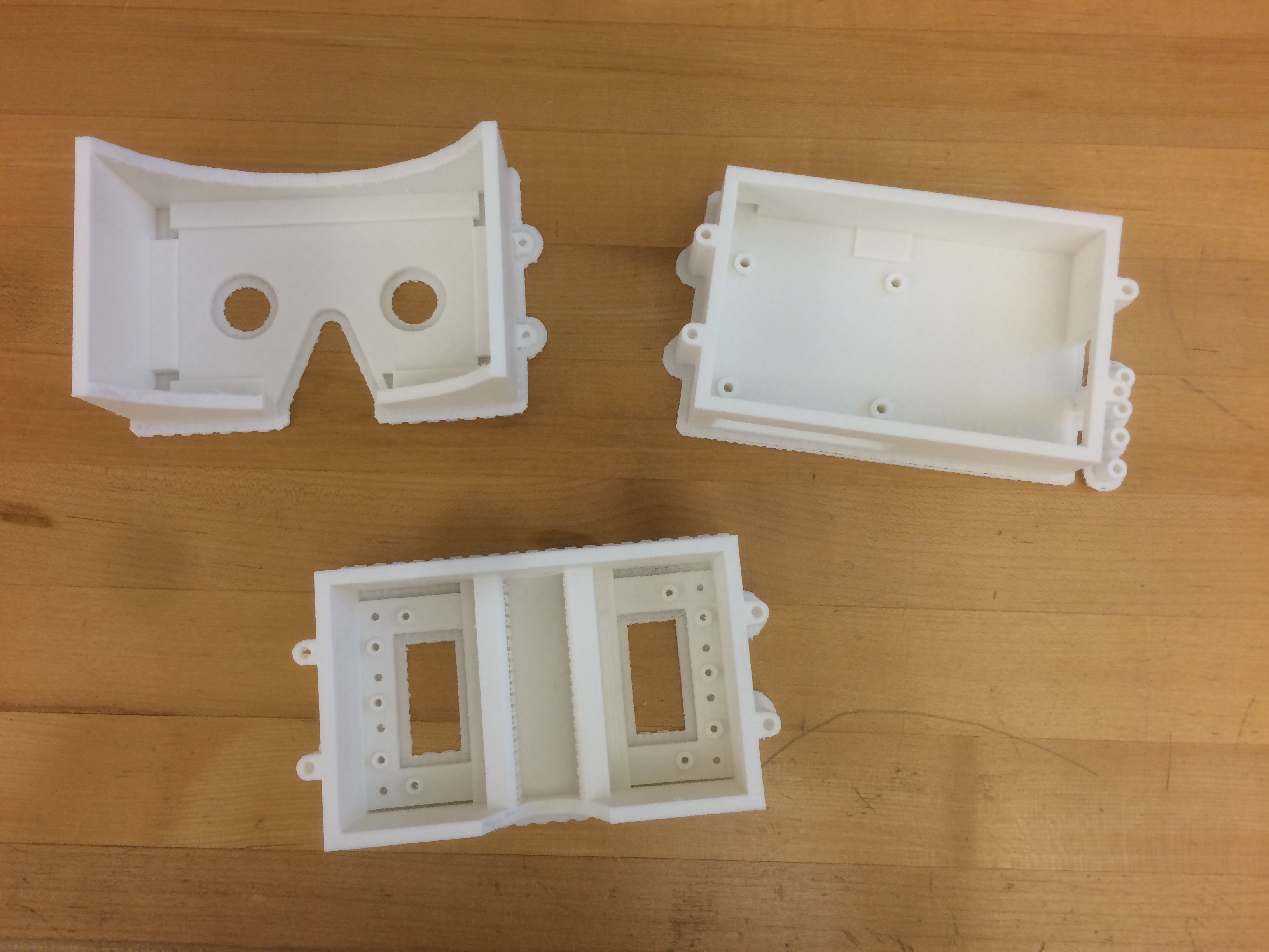
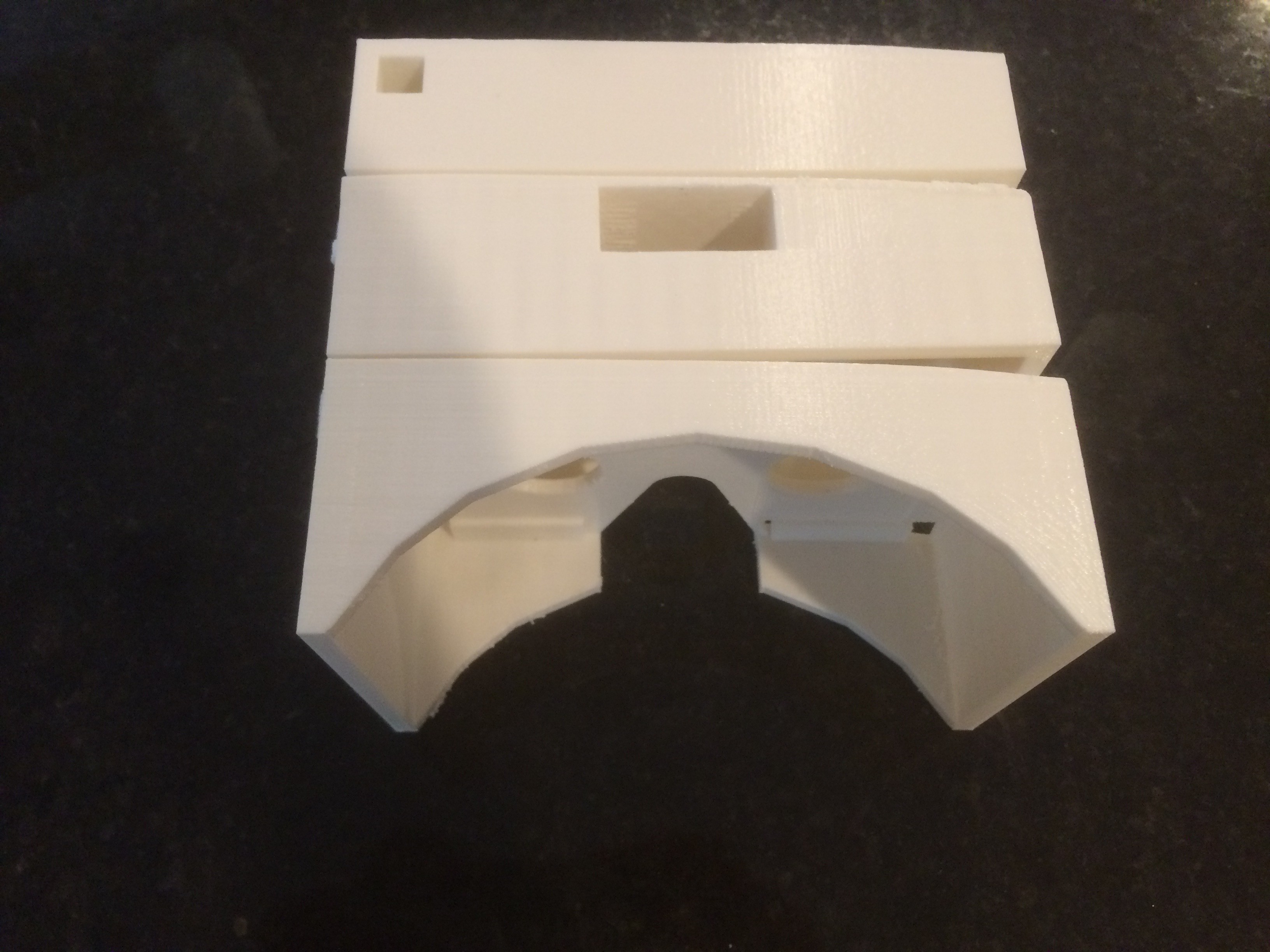
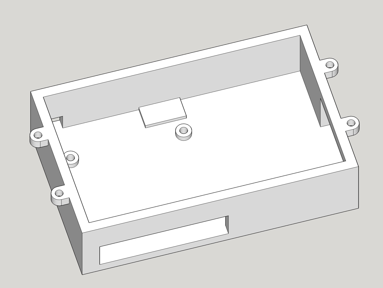
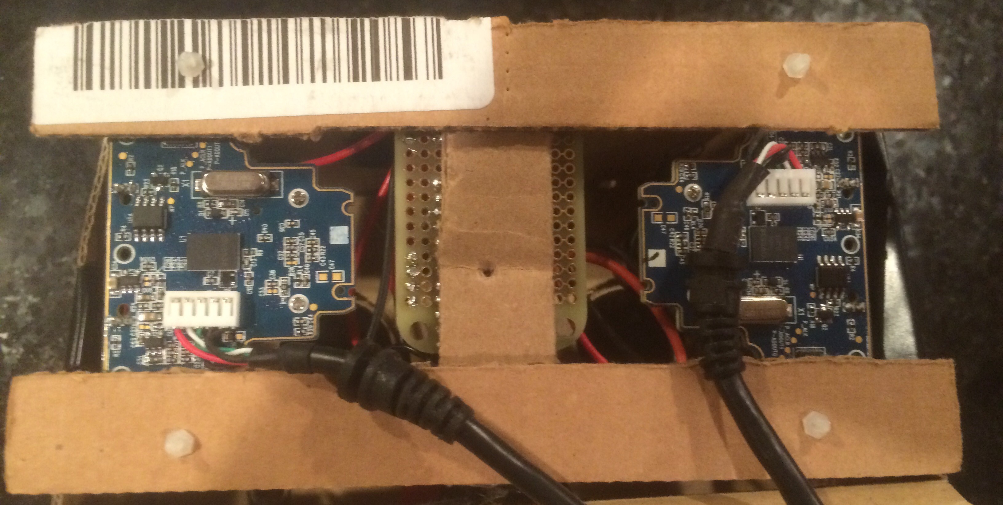
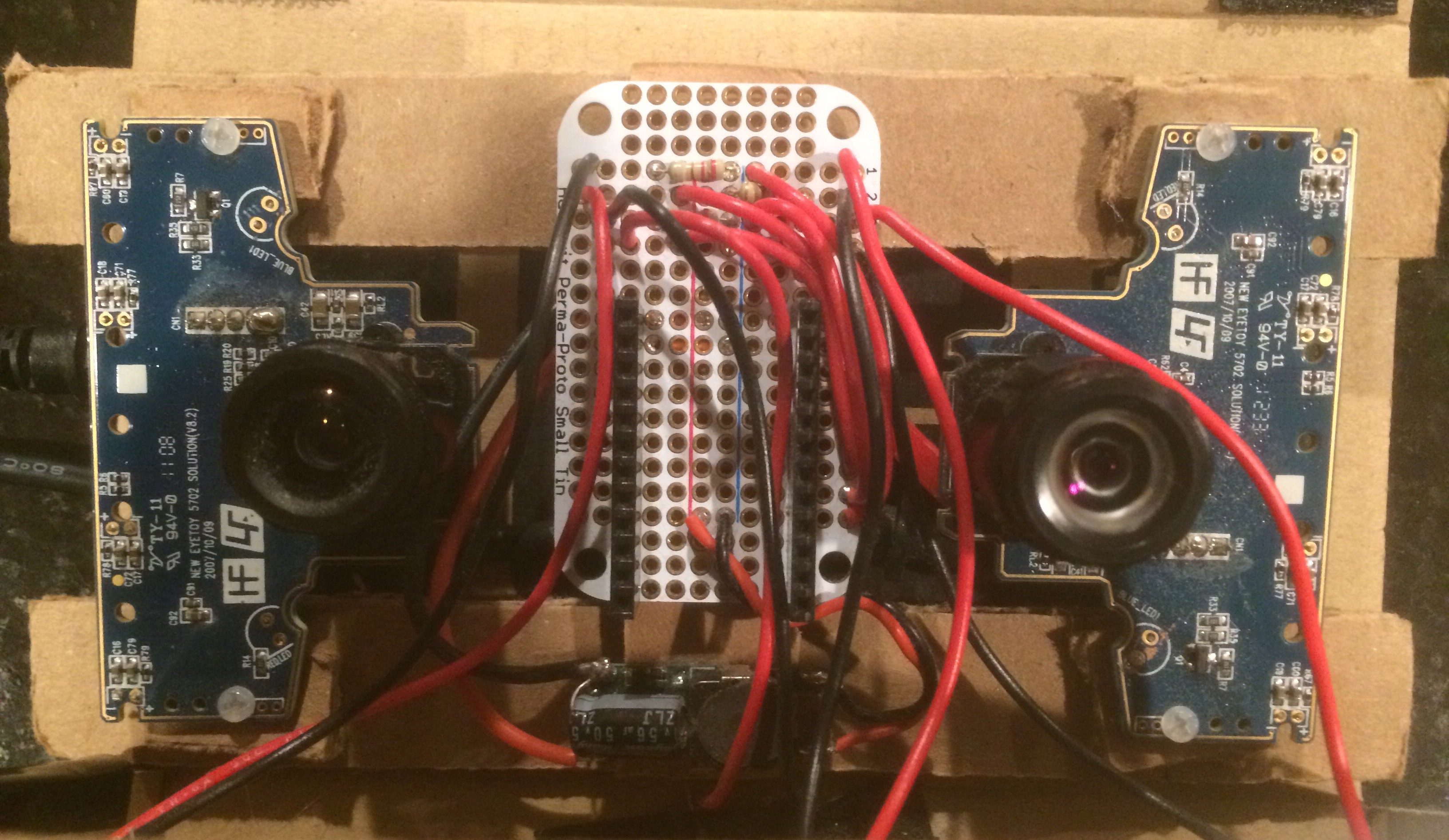
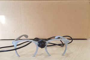
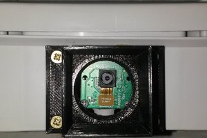
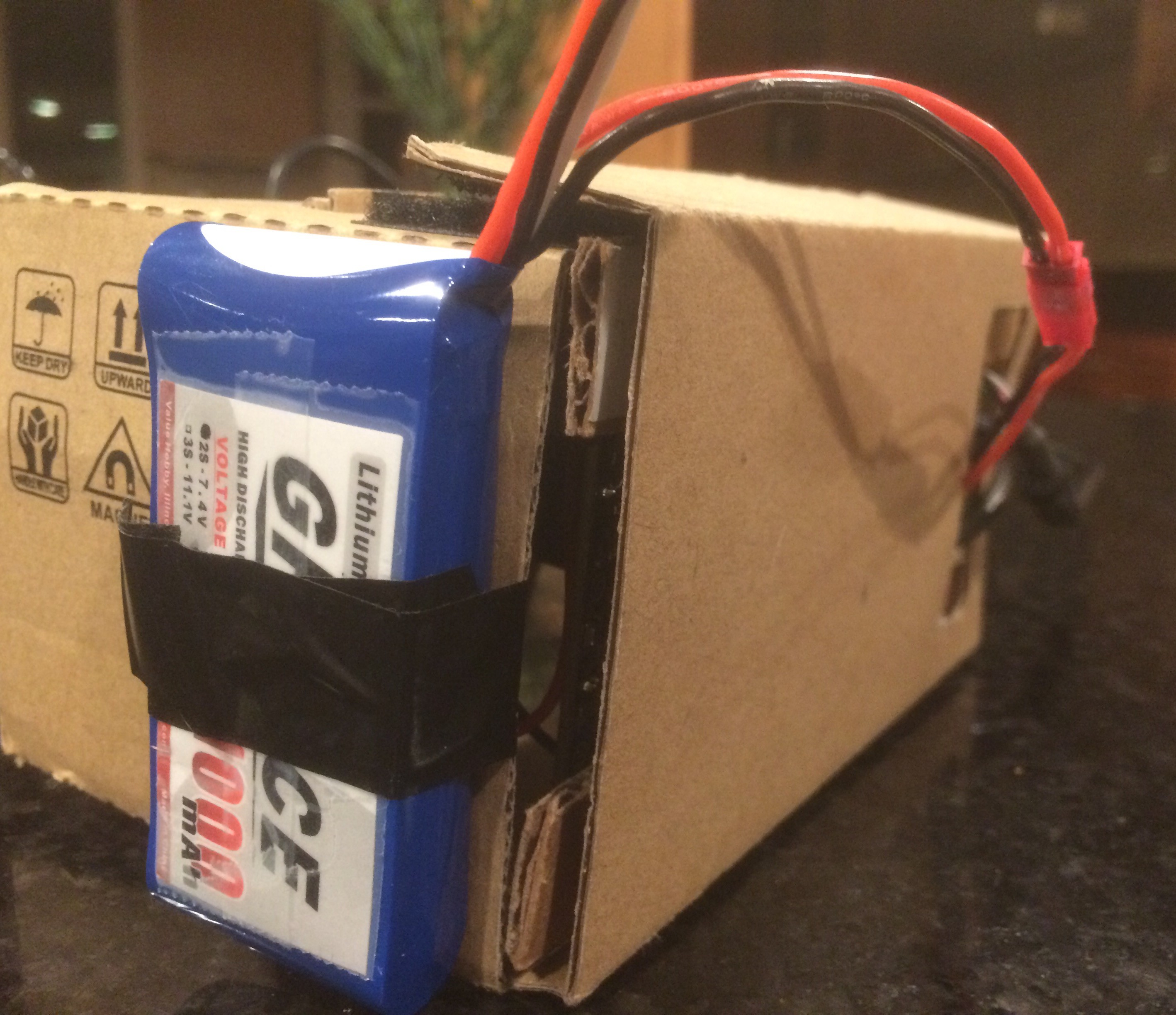
    Our prototype was finished! Here's a picture of the completed device (if you look closely, you can see the Playstation cameras and some of the circuitry inside the Cardboard):
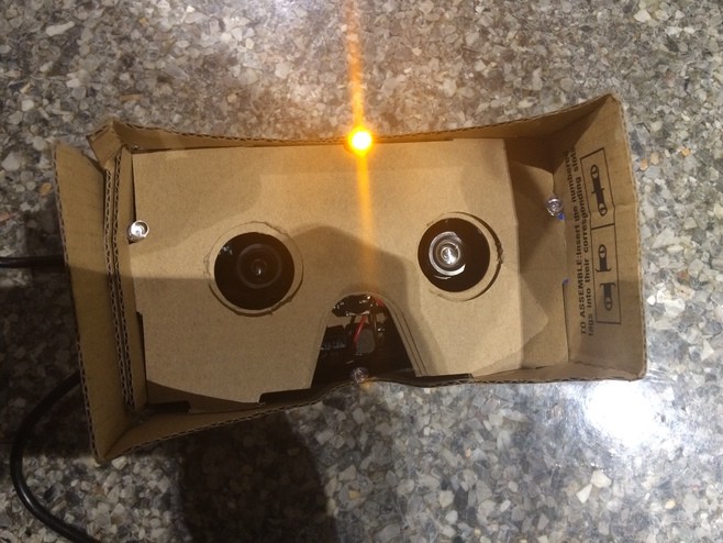
  • Concept Origin

    Stephen06/17/2016 at 18:48 0 comments

    PennApps XII, September 2015. ~18 hours in.

    Having found our original augmented reality hack to be overly ambitious given the time that we had, we were searching for a new idea to pivot to. As we were thinking and discussing, a sponsor came over and started talking to us. Before long, we had our new idea: something to help diagnose concussions, based on a person's eyes' responsiveness to motion.

    The link between a person's ability to track movement with their eyes and the severity of a traumatic brain injury is well-established. When a doctor moves their finger side-to-side to see whether a patient can follow it, they're trying to see whether the patient's eyes can move in response to stimuli to diagnose a potential brain injury. Studies have verified the relationship between eye movements and concussions as well; for example, see Samadani et al. (2015).

    Since commercial equipment to diagnose concussions was already available, we knew our key advantages would have to be cost and portability. We also recognized the advantage to potential victims of concussion that low cost and high portability would bring: access. A coach or trainer can have a $100, Google Cardboard-sized device on the side of the field. They can't have a huge machine that requires special training, lots of electricity, and tens of thousands of dollars. This is especially true in youth sports, where budgets are small and teams often can't afford such expensive equipment as a result.

    To give an idea of the severity of the problem, 3.8 million concussions were reported in 2012, double the number reported just a decade before. Approximately one third of the reported concussions from sports happened at a practice, which are unlikely to have medical personnel nearby to diagnose—and this is almost certainly an underestimate, since many concussions in sports go unreported and undiagnosed. Without a diagnosis, people are more likely to suffer repeat concussions, greatly increasing their chance of permanent damage or even death.

    As we considered the magnitude of the problem, and the science behind a potential solution, HeadsUp was born.

View all 6 project logs

Enjoy this project?

Share

Discussions

Similar Projects

Does this project spark your interest?

Become a member to follow this project and never miss any updates