 ThunderSqueak
Goals at a glance:
- Learn what actions are best for a given situation ("instinctive" based learning AI)
- Voice/audio recognition with a learning system.
- Be able to display situational emotion.
- Exploration of the environment.
- Track objects.
- Judge distances.
- Fetch a ball or other object as verbally directed.
- Perform simple tasks after learning them in an organic manner.
Challenges:
- Design and implement the robots body (needed for the Squirrel system described below)
- Develop the voice/audio recognition system
- Develop the learning AI that makes use of this body (Squirrel system)
How the Challenges are addressed (or Divide and Conquer):
This project consists of 3 primary challenges, each is broken up into smaller bites for easier consumption.
The mechanics:
This particular portion of this project has me stepping out of my comfort zone, as such I am learning a lot about mechanical stresses and servo/stepper motor design. The reason I chose to do this portion of the project first is twofold. The initial idea behind the AI is to use an instinct based system in what I have dubbed "Squirrel". One way to go about this is to design the body that will be used in order to understand what the best instinct choices would be. I considered simulation, but what fun is that? I have broken up this task into several parts.
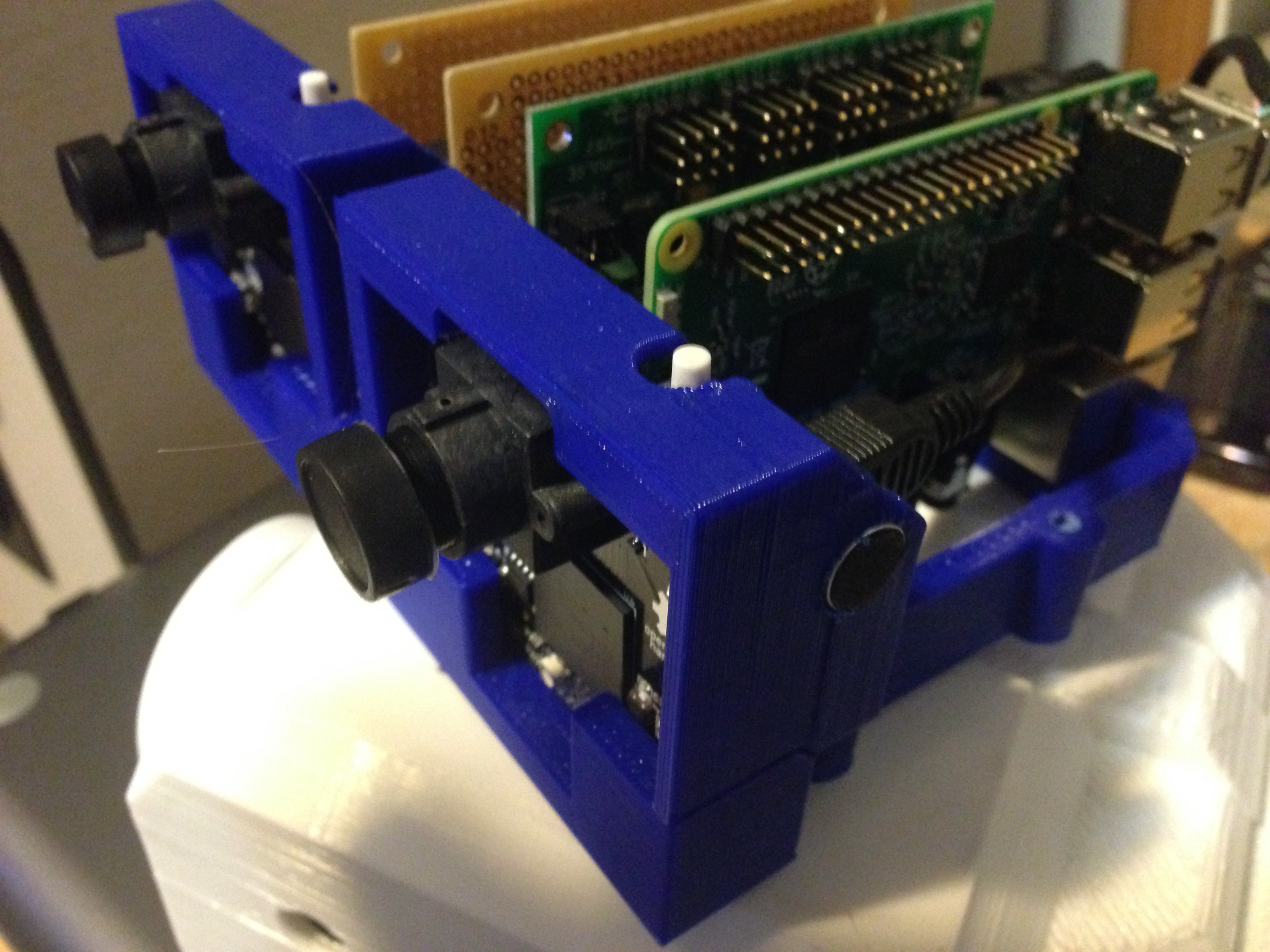
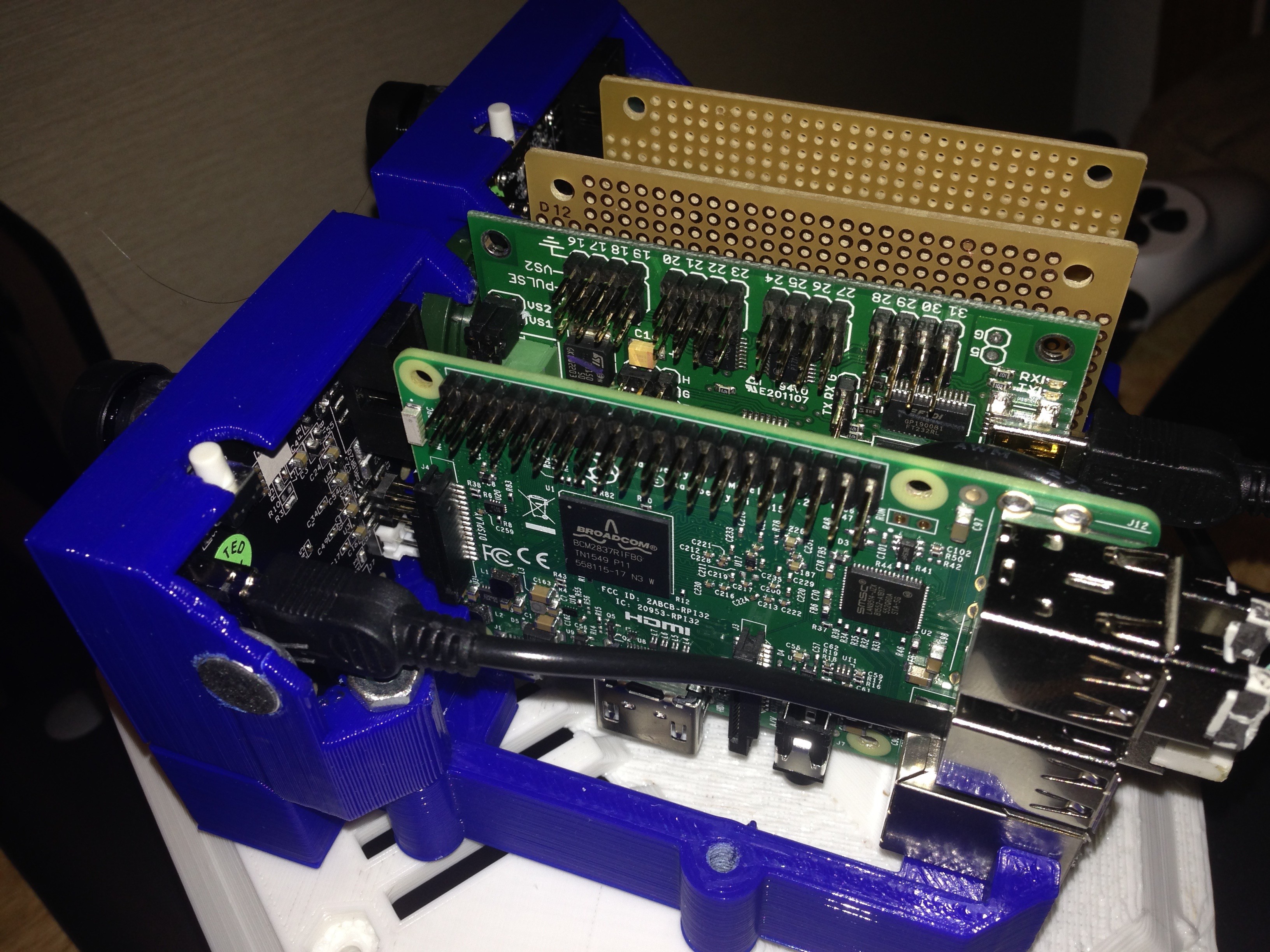
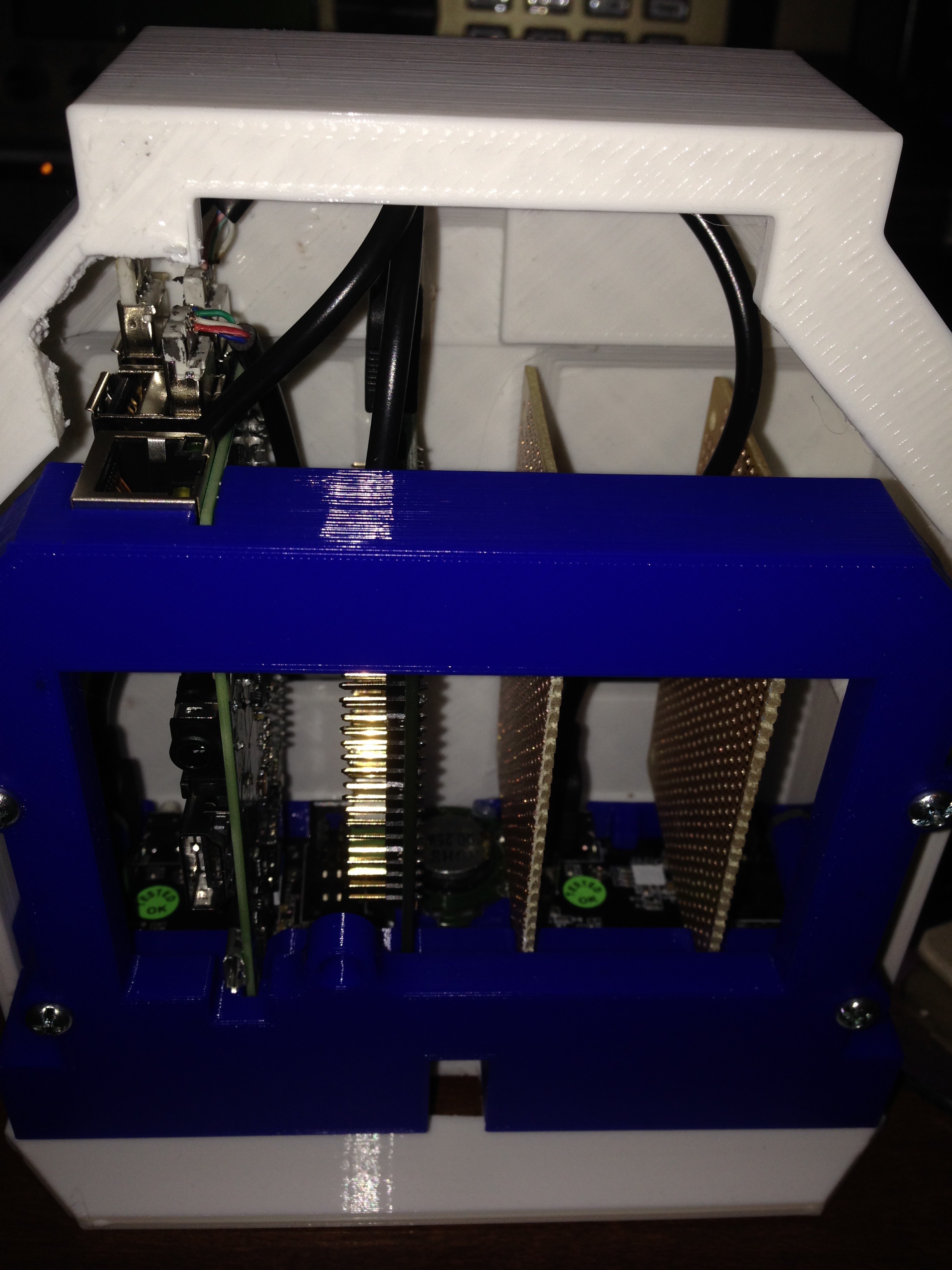
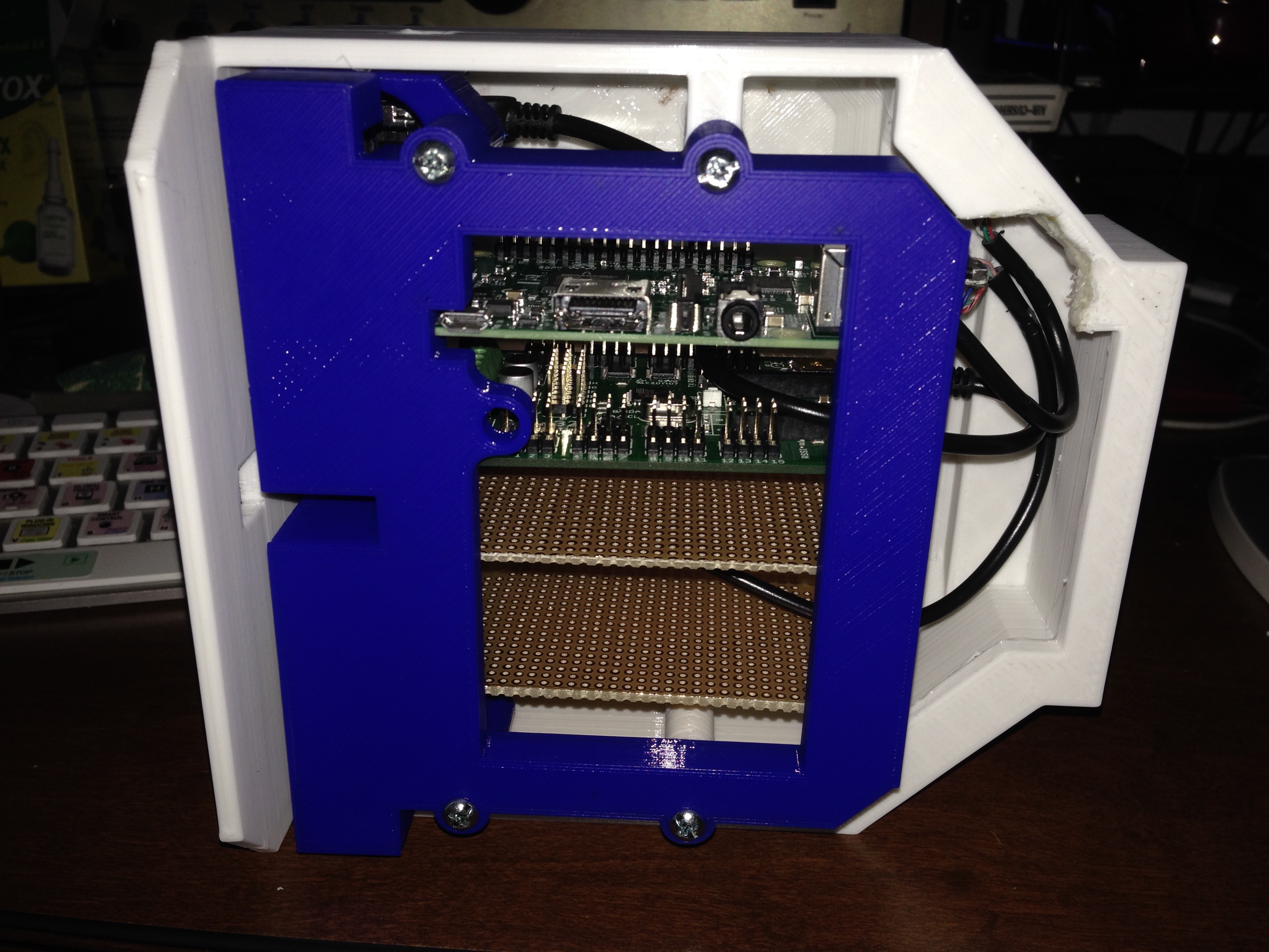
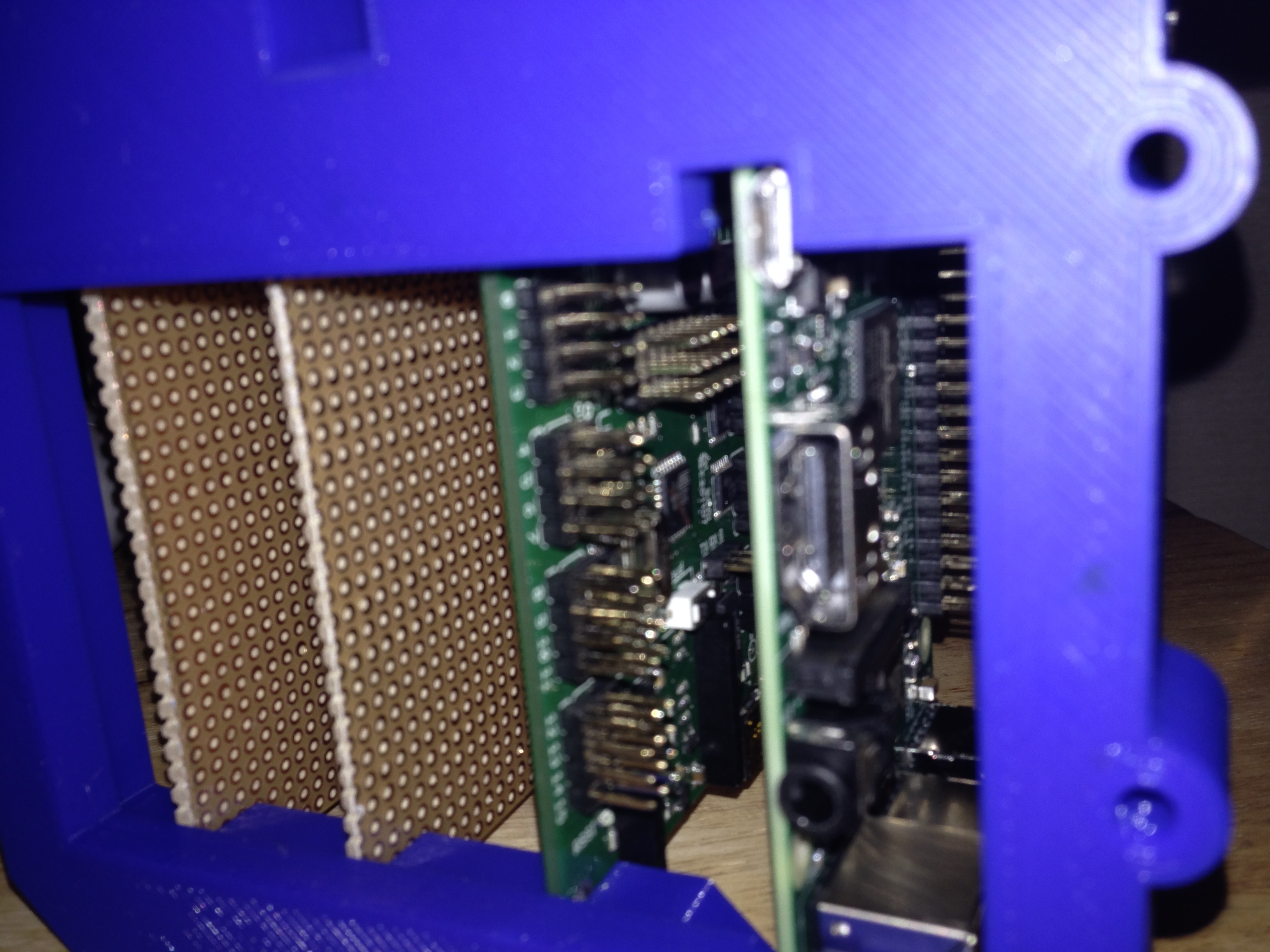
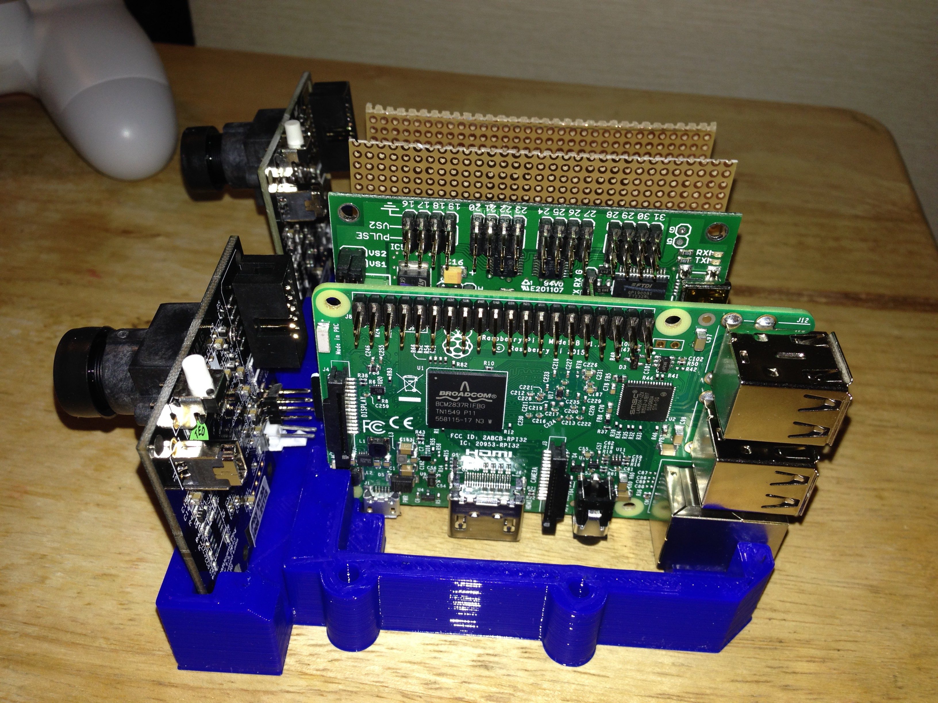
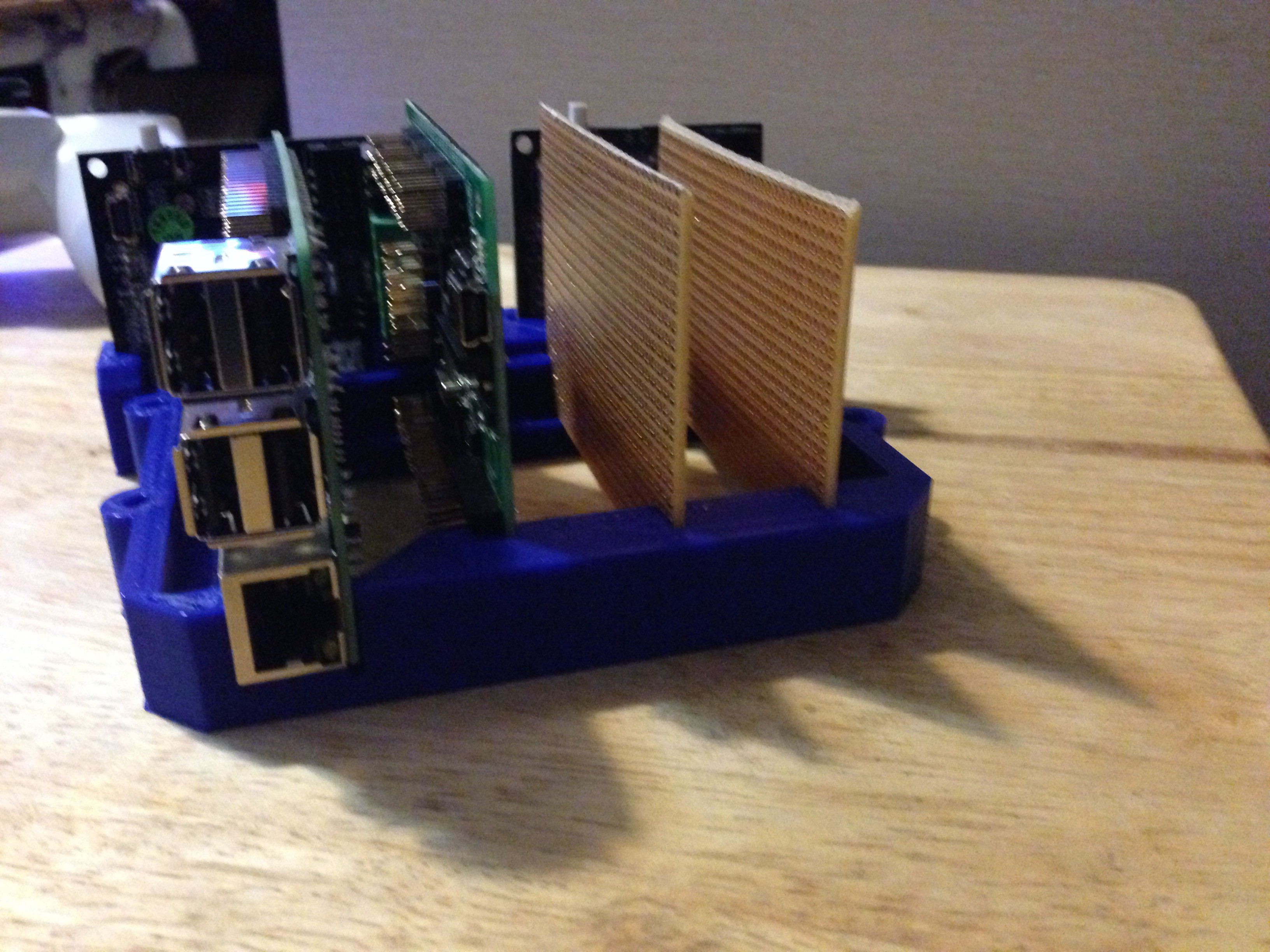
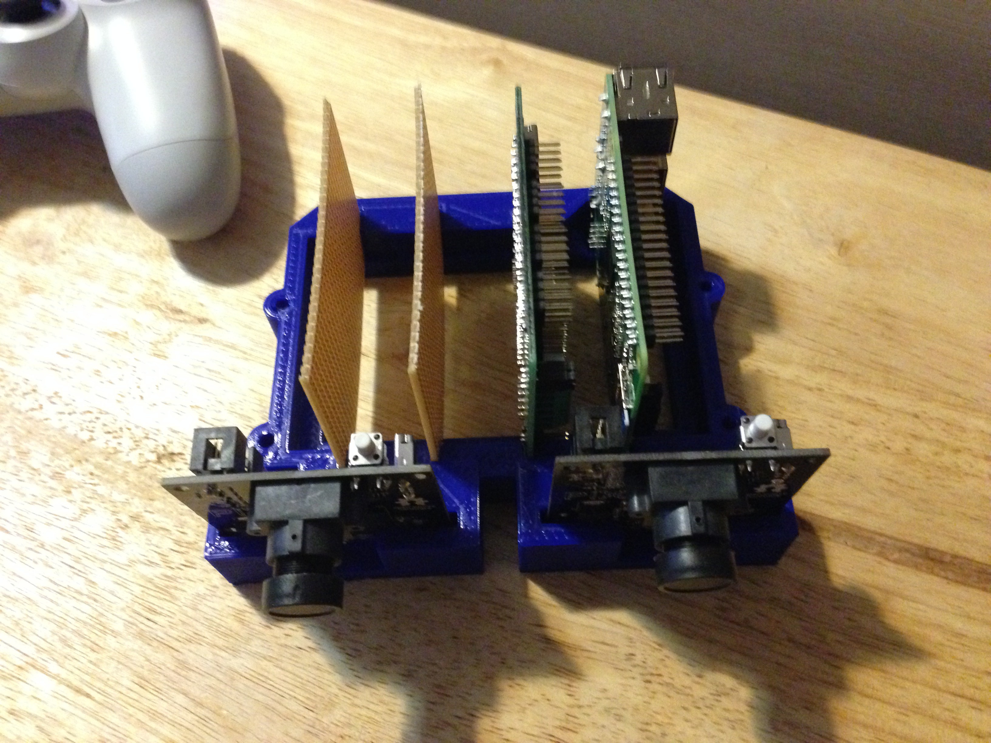
- Design and construct the brain layout as this will dictate the proportions of the rest of the robot.
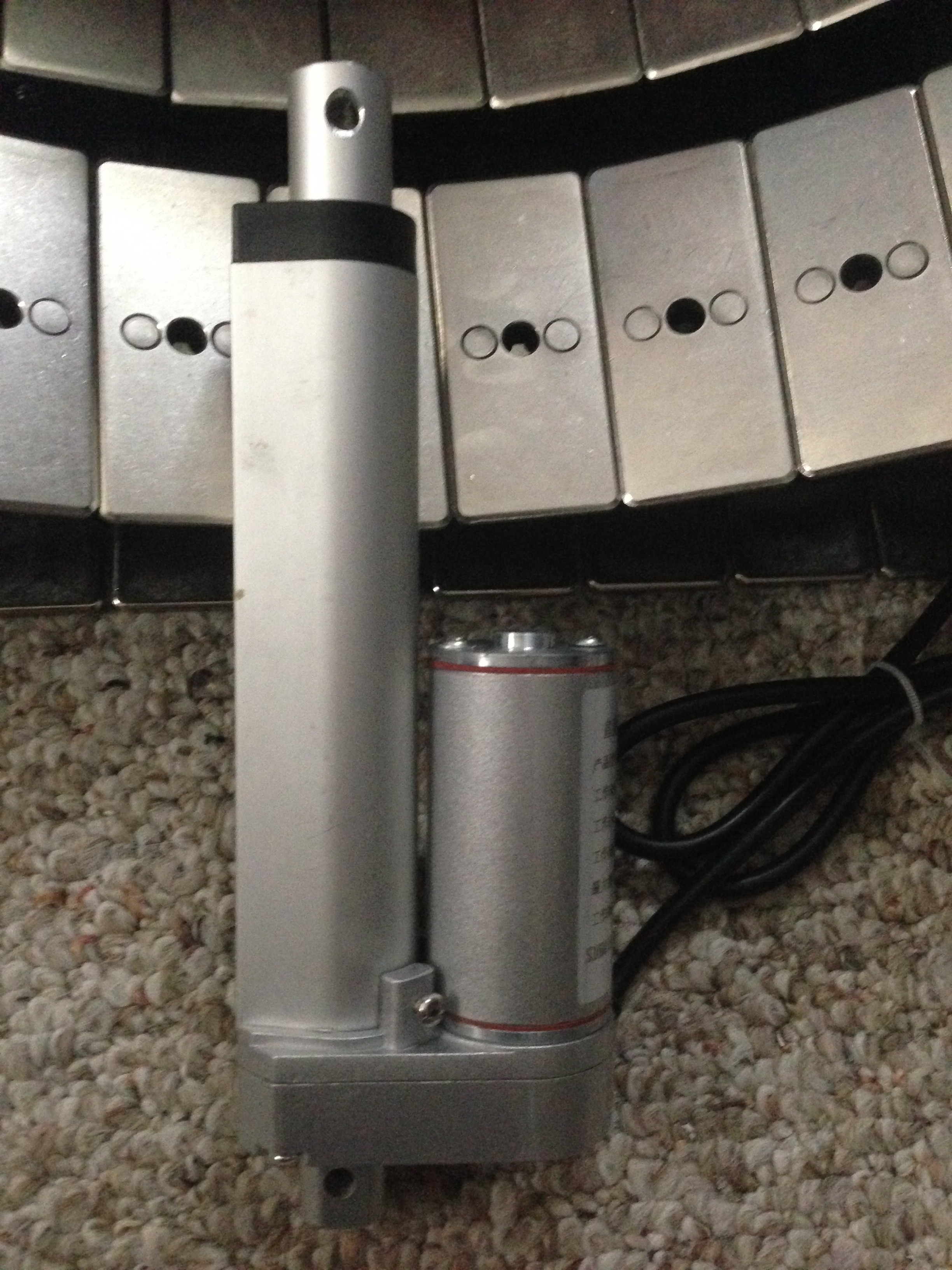
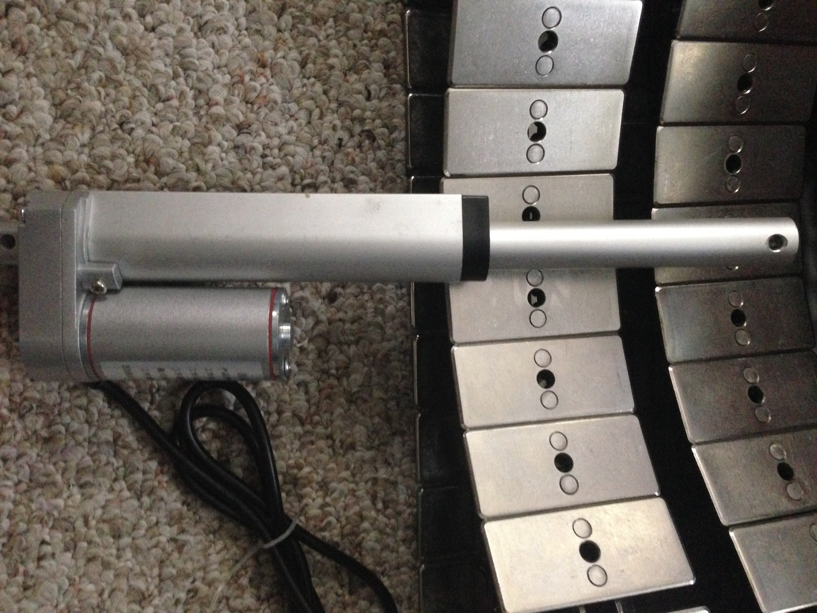
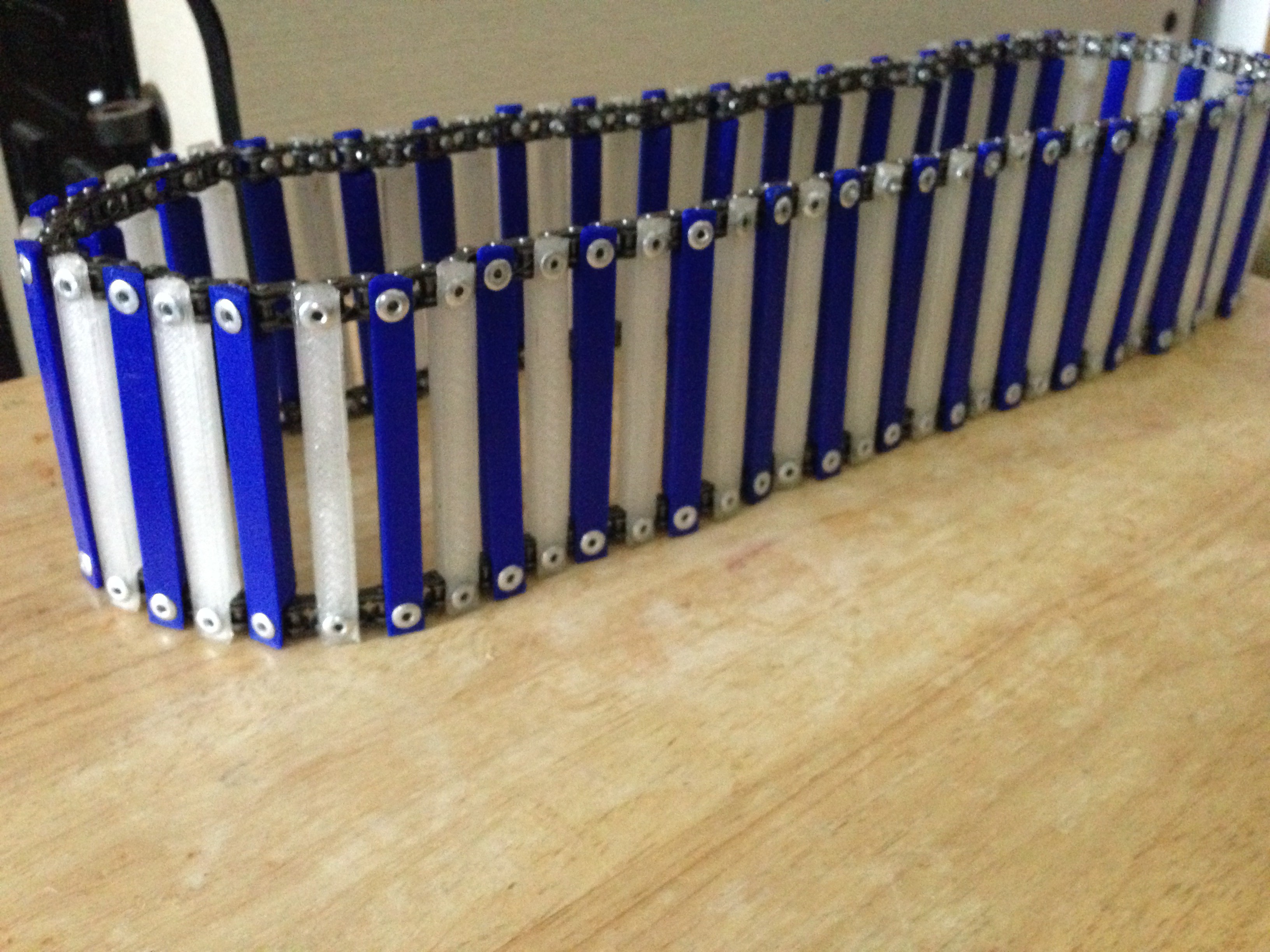
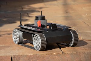
- The second task will be to design and construct the lower track system and implement the mechanics required to allow for locomotion. This is also where the battery is located in order to keep the center of gravity low.
- Design and construct the body portion that will allow for a vertical movement of the head and arms. In the "chest" there will be a compartment that contains the DC motor controllers as well as any electronics that did not fit into the head unit.
- Design and construct the arms. In this area I am planning on implementing a 5 degree of movement limb. Two in the shoulder join, 1 in the elbow, two in the wrist. Part of the challenge in this is to be sure that the robots arm is strong enough to lift small objects while also keeping their weight very low.
- Design and construct the "hand" section. In this area I am looking at several techniques that can be used. The first idea is to implement a modified 3 digit gripper design. This gripper will be controlled by control lines in order to keep the weight to a minimum. Other ideas considered include vacuum systems, and “coffee filled balloon” systems.
The mechanical construction will be made of easily obtainable aluminum stock when practical, other components will be 3D printed in PLA or modified from purchased components when convenient and economical . The idea is to make this project easy to duplicate by others.
The Voice/audio recognition system:
I am choosing to stay away from standard voice recognition systems so that I may explore and come up with something slightly different. Many of the already robust and available systems on the market require an online connection or are very complex in their design. One of the design choices already in PAL is to include a Raspberry PI 3b as the primary computer, this will allow many of these other systems to be implemented should anyone constructing their own PAL wish to adopt a more standard approach.
This part has two primary components, a speech output system and an audio recognition system. I say audio recognition as the way this is implemented is that a sound is broken up into key frequency blocks and the db levels of each of these blocks is then analyzed with the result being shipped off to the primary computer.
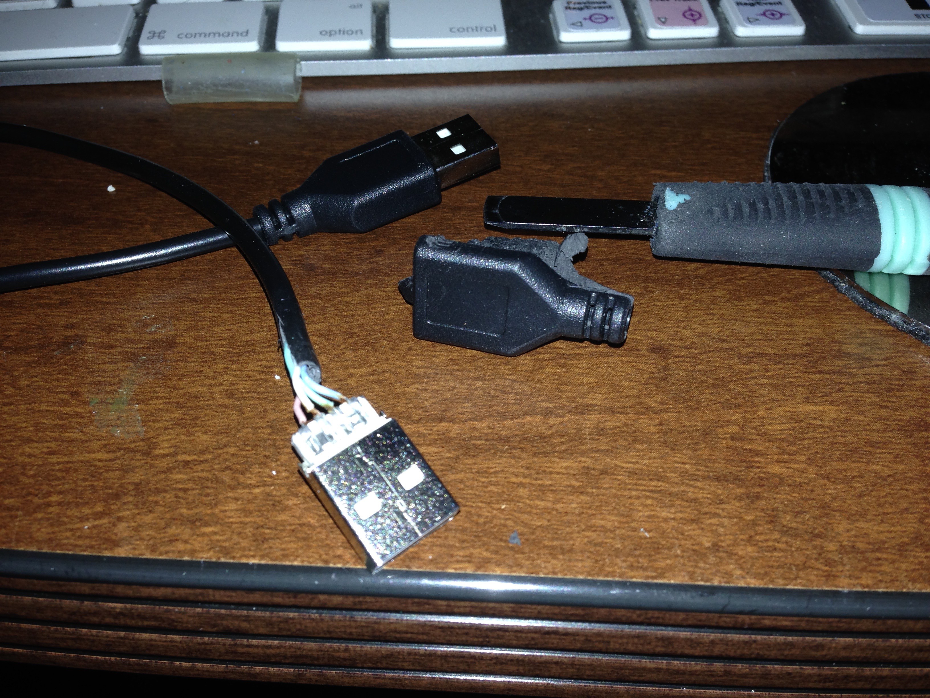
- The Voice will be relatively a simple system consisting of a TTS256, a speakjet, and a pic16f1459. The pic16f1459 is used as a USB to serial converter as well as other duties...
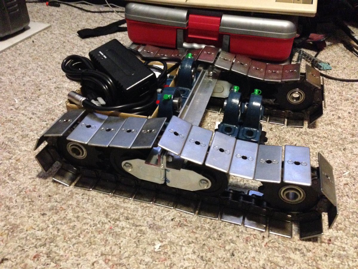
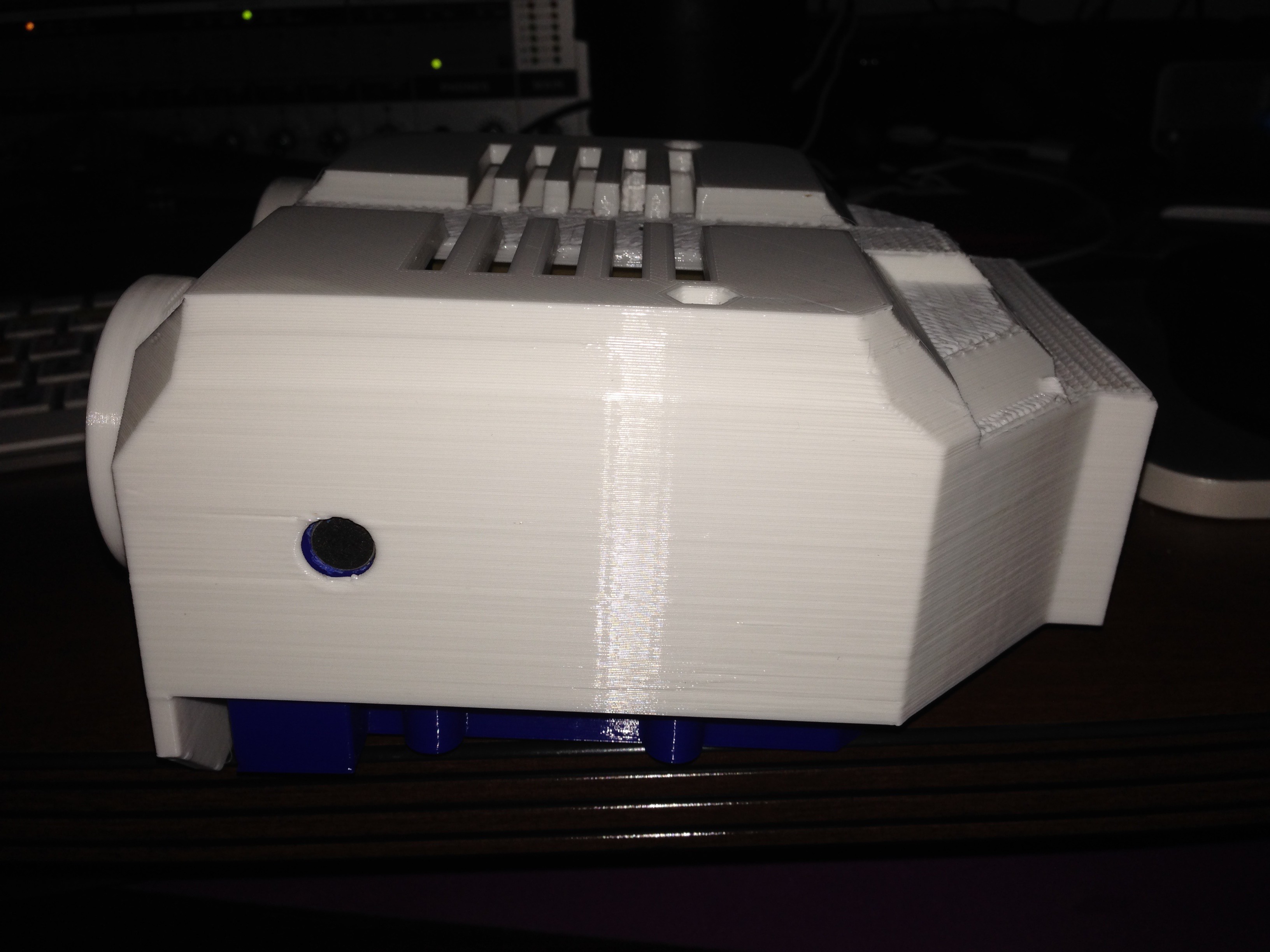
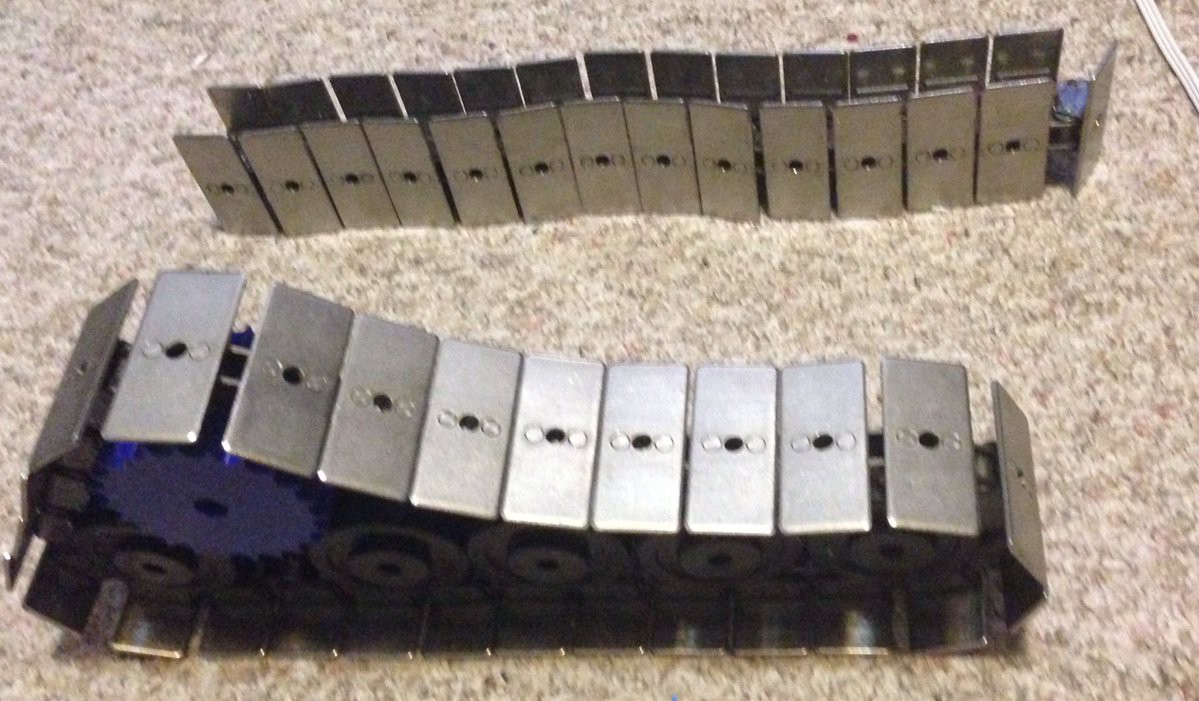
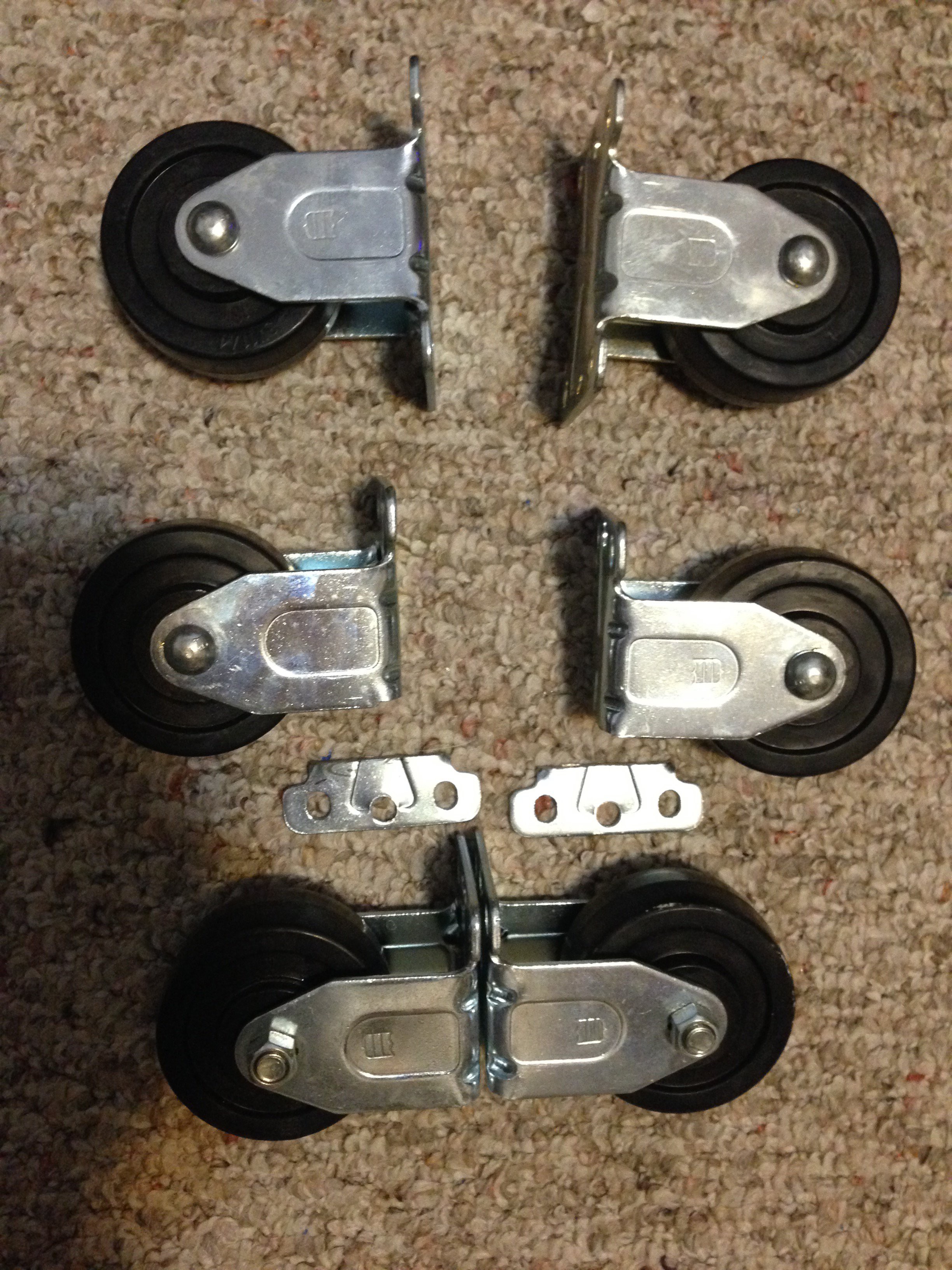 By cutting off the one side of each caster, they have enough clearance to allow the parts to roll comfortably. The thought is that in the final design it will end up looking something roughly like this. Please note, I am waiting on sprockets to arrive in the mail, so those parts are substituted just to give an idea of the basic shape.
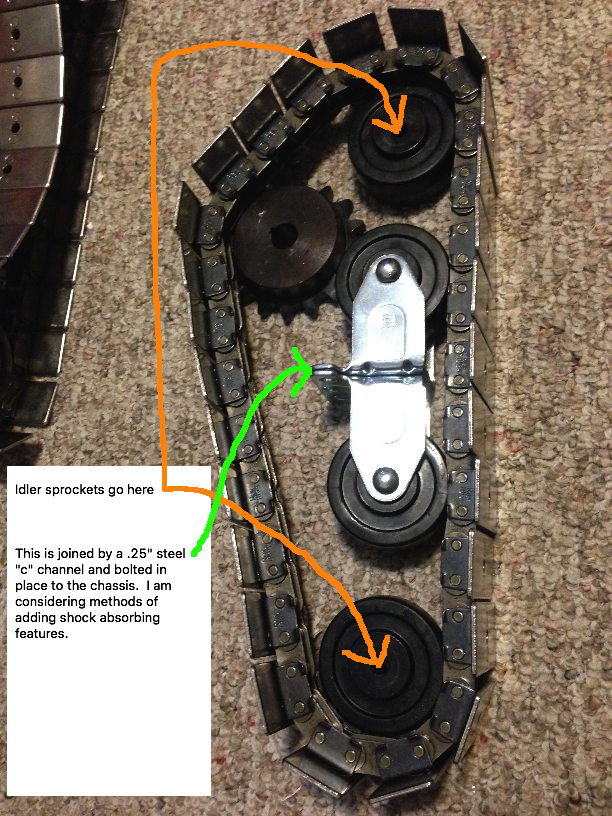
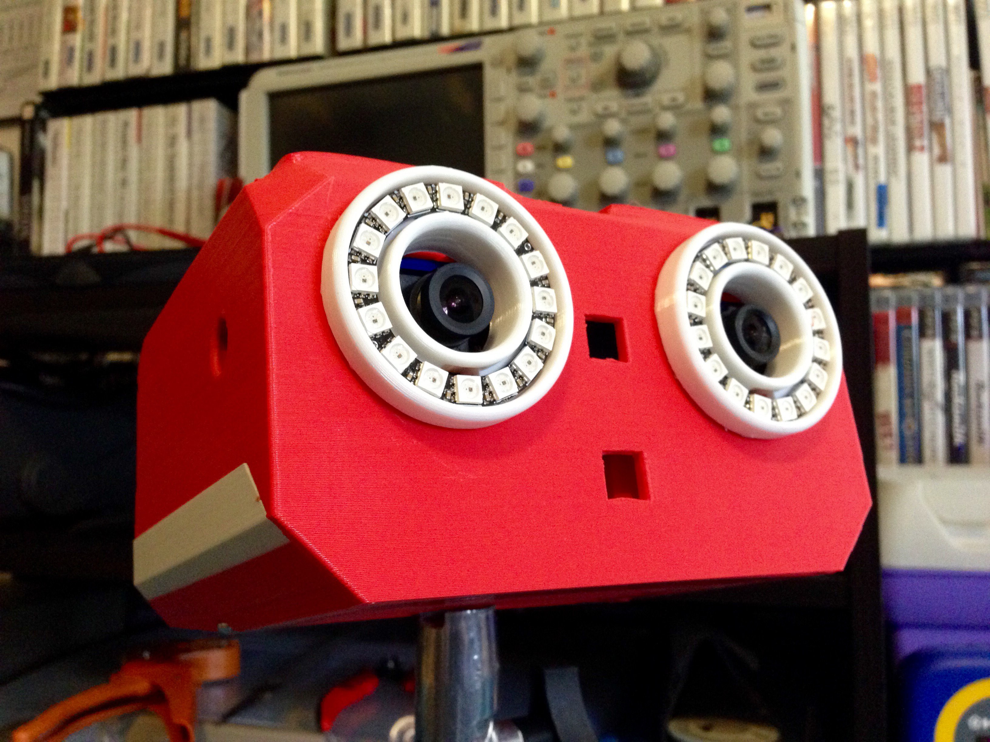
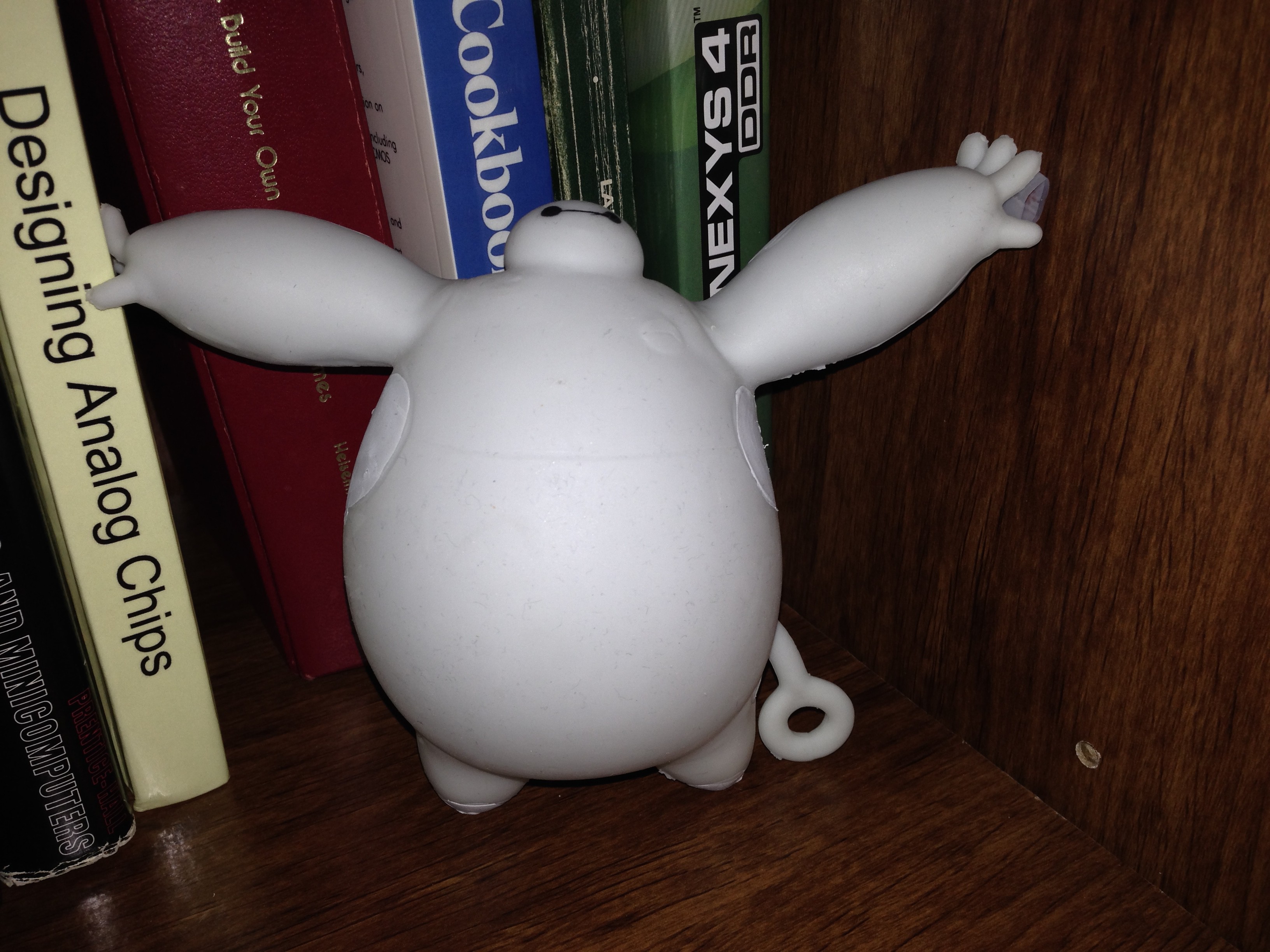
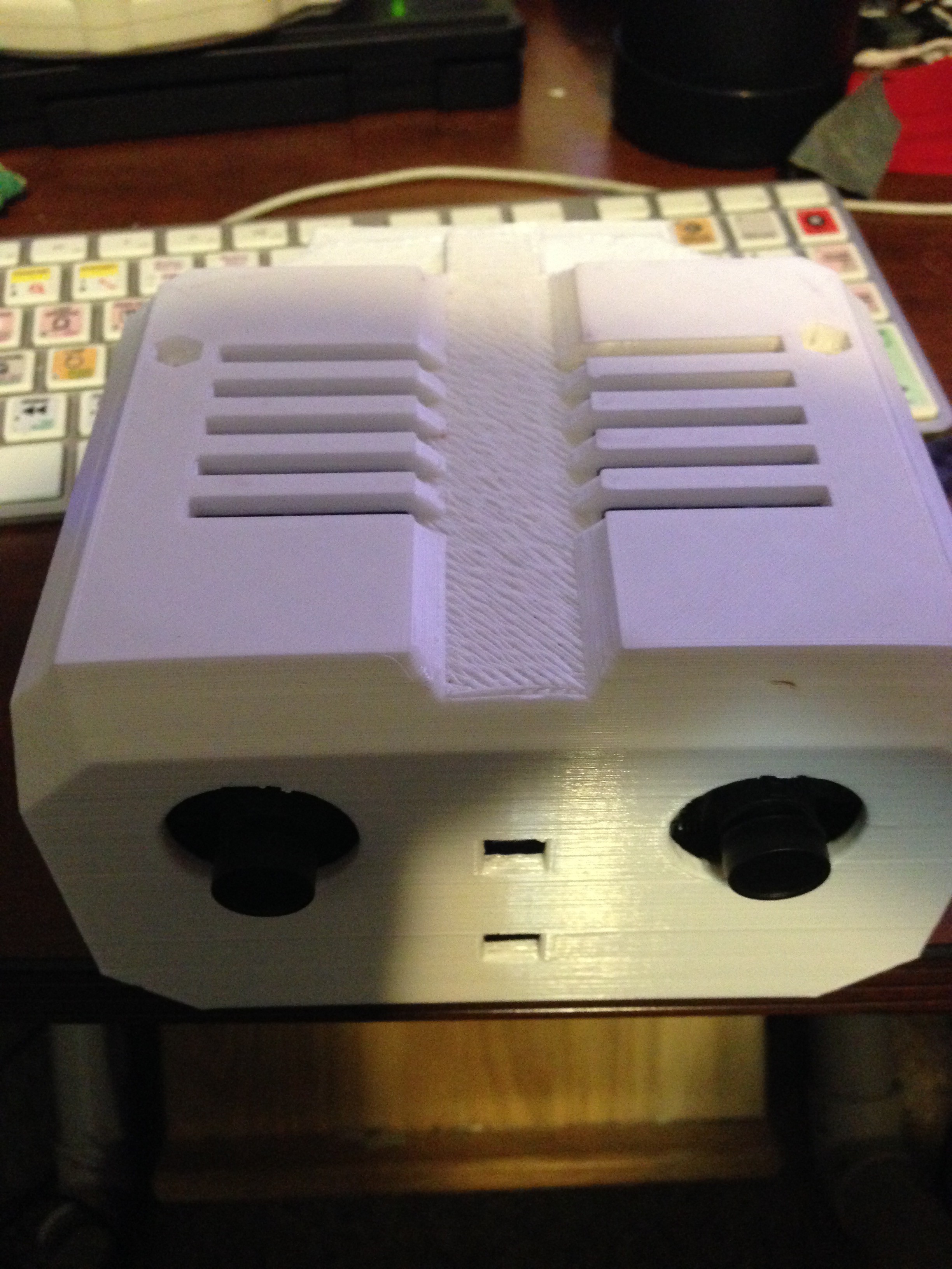 That is one blank stare XD
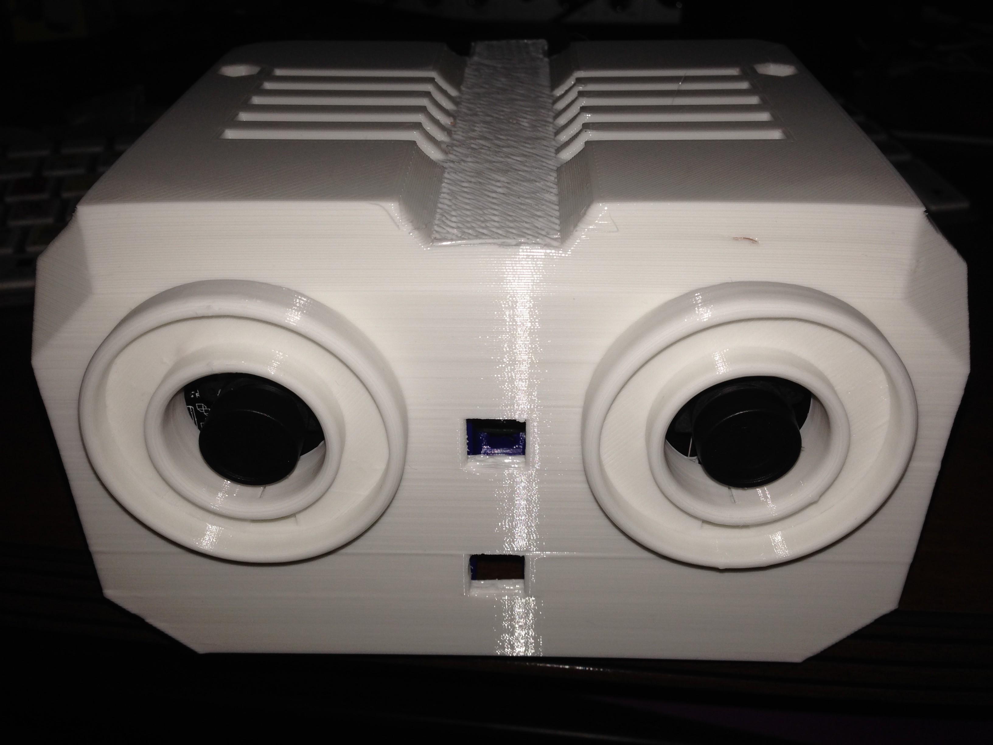
 That's it for this 5 minute update :)
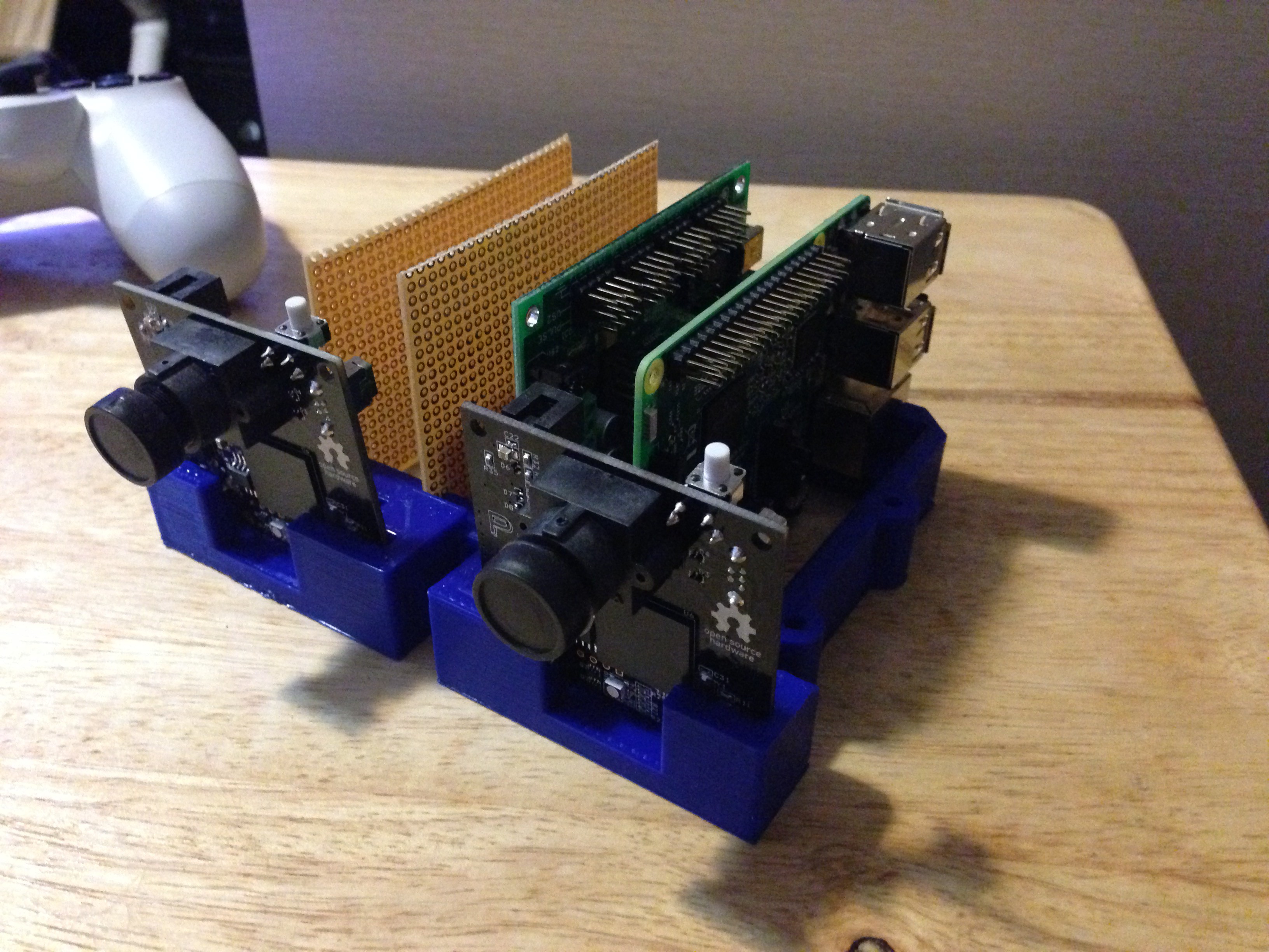


 Maximiliano Palay
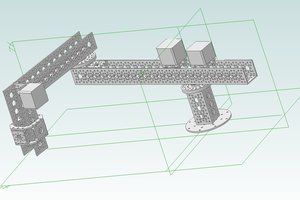
 Joshua Elsdon
 Paul Crouch
hello i am new to hackaday, how is this project coming along.