 Simone Tolomei
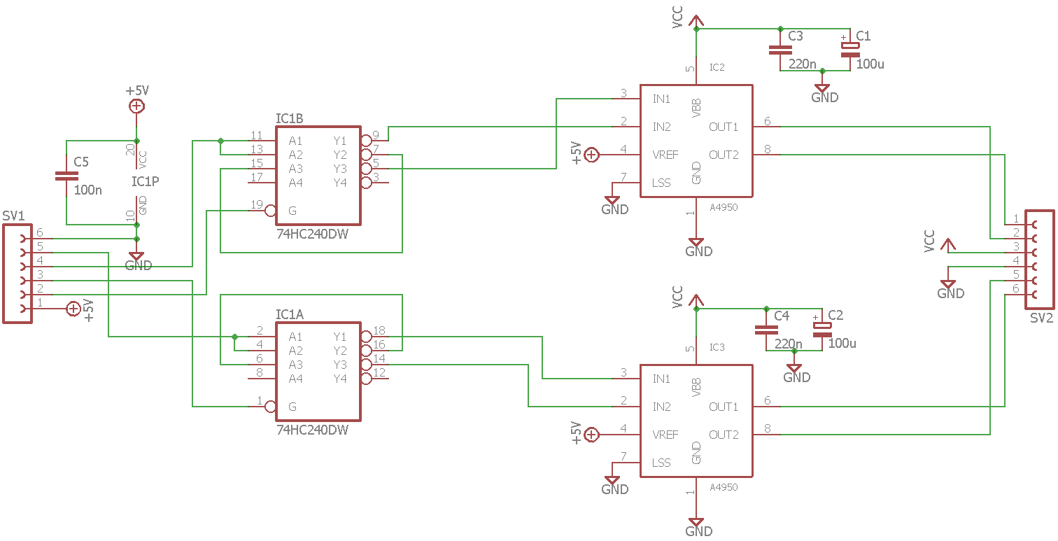
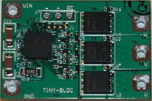
The circuit is very simple, basically it consists of two A4950, the 74HC240 and five bulk capacitors.
The ENABLE pin of the inverter is used to set LOW both the Input signals of the A4950, setting it to low power mode.
The A4950 can also provide a current feedback, but the sensing resistor also triggers the automatic current limiting system of the IC, that decrease the maximum output current. For example, a 0.25ohm resistor would limit the maximum current to 2A. This is the reason why i choose not to use the current sensing in this version of the board. If you want to use the current sensing feature you can use a external ammeter IC or consider the powerful uBridge by Officine Robotiche.
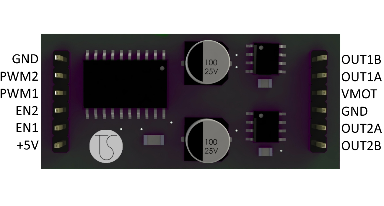
Basically this is a H Bridge, the only difference between this and the other typical commercial bridges is the integrated LAP control, this mean that you can control both speed and direction using the same signal. In particular:
| PWM duty cycle | Motor speed |
|---|---|
| 0% | Full Backwards |
| 50% | Brake |
| 100% | Full Forwards |
The ENABLE pin is used to disable the bridge. When LOW the bridge is operating at normal condition, when HIGH the bridge will enter in low power standby mode after 1ms. This is useful because the brake condition, with duty cycle 50%, means that the motor is braked, and it will draw current to remain still. This is the worst efficiency condition for the bridge, then, unless with small motor, it will heat up very fast. I recommend you not to remain in brake condition for more than a half a minute. Therefore, for simply stop the motor you can set duty cicle to 50% and then disable the bridge with EN pin.
 Juan-Antonio Søren E.P.
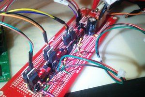
 ridonkulus
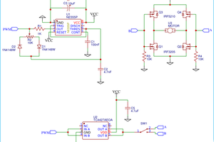
By reading the details about the A-Bridge, I am totally convinced now that I should make the decision of investing in it. Hopefully, this product would be able to provide the same benefits as what it is talking about. I have been thinking to visit the home of an authentic website where I could read the reviews of essay writter before hiring him for help in an essay that I am writing about this topic.