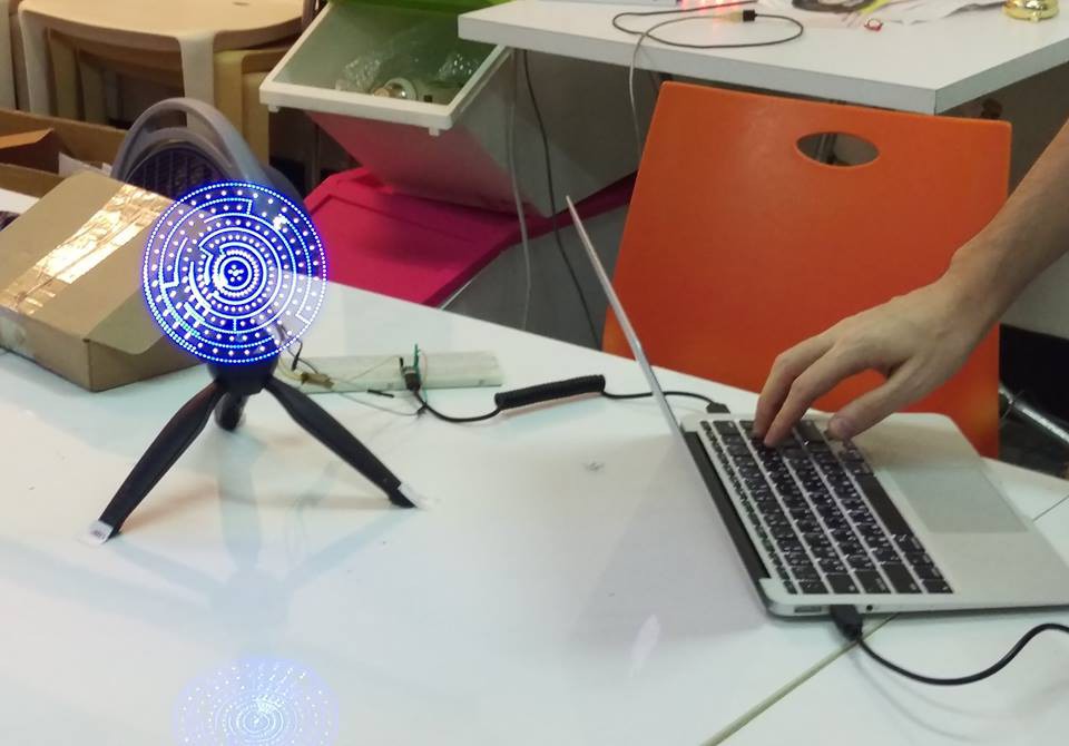
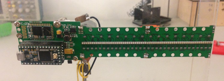
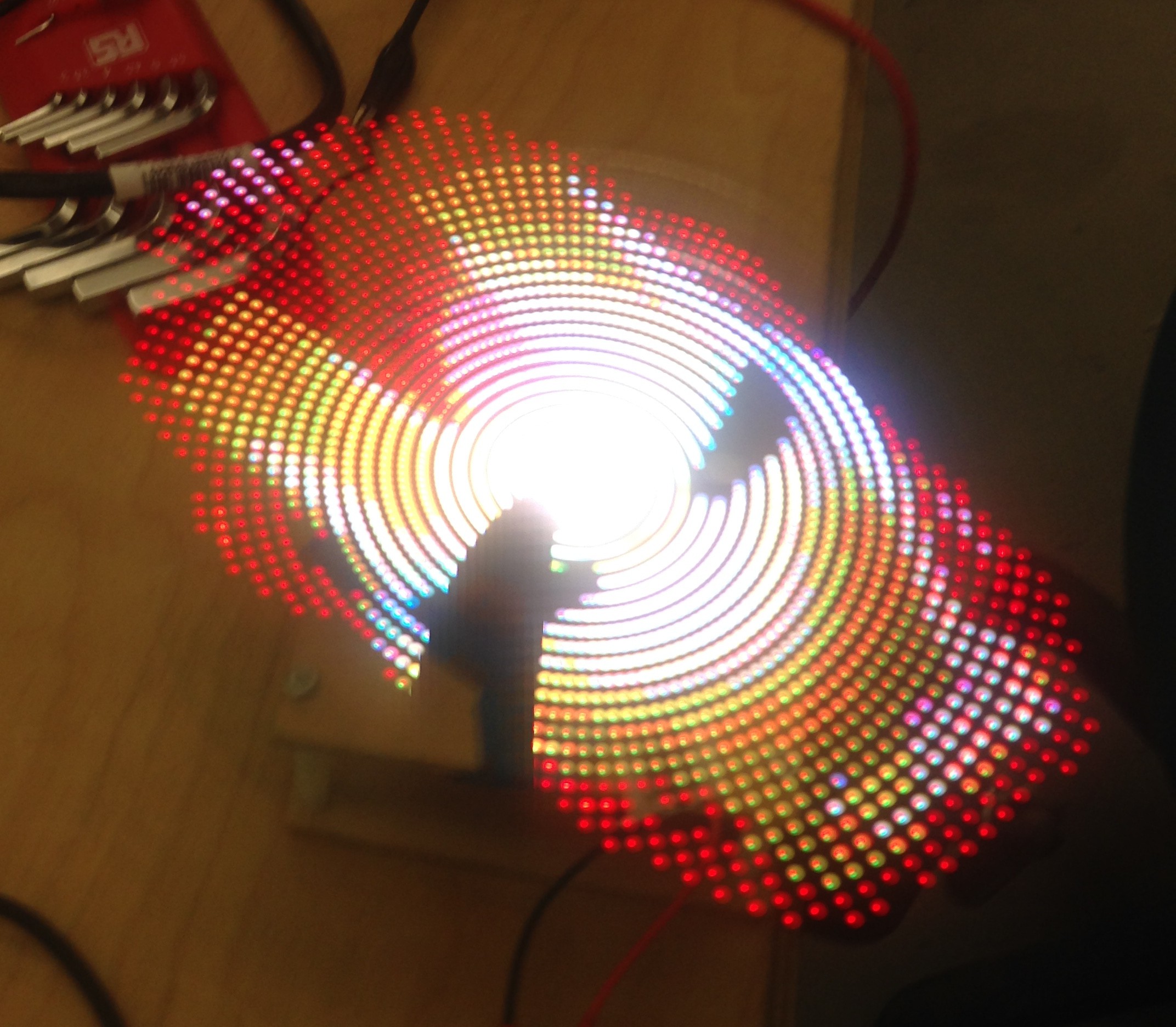
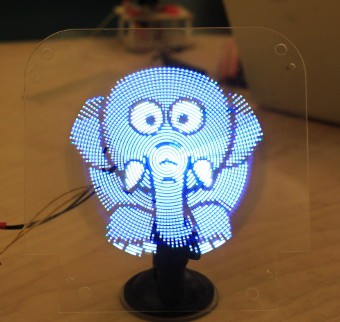
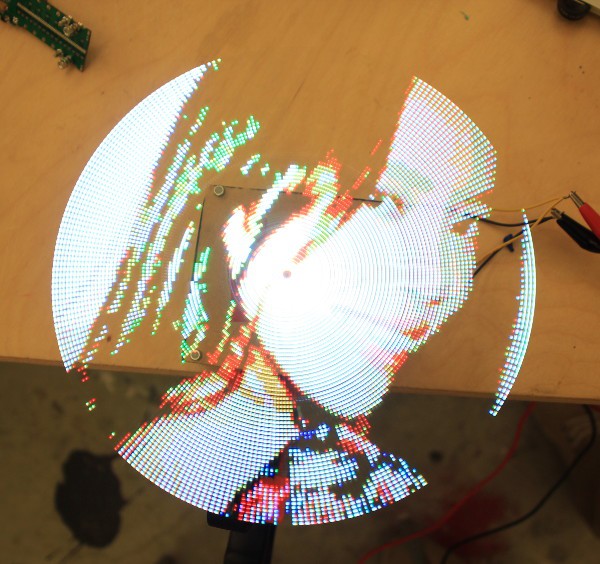
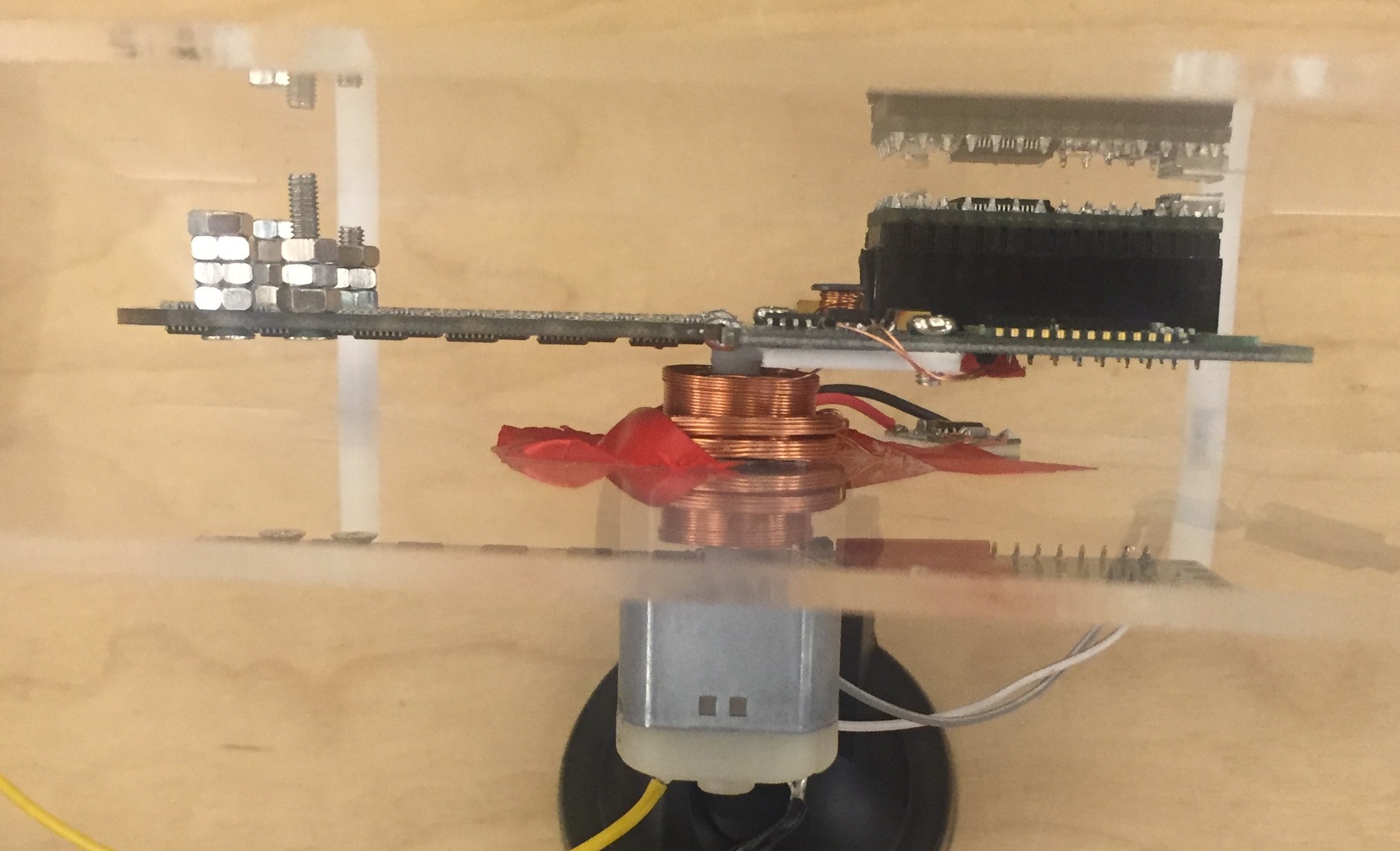
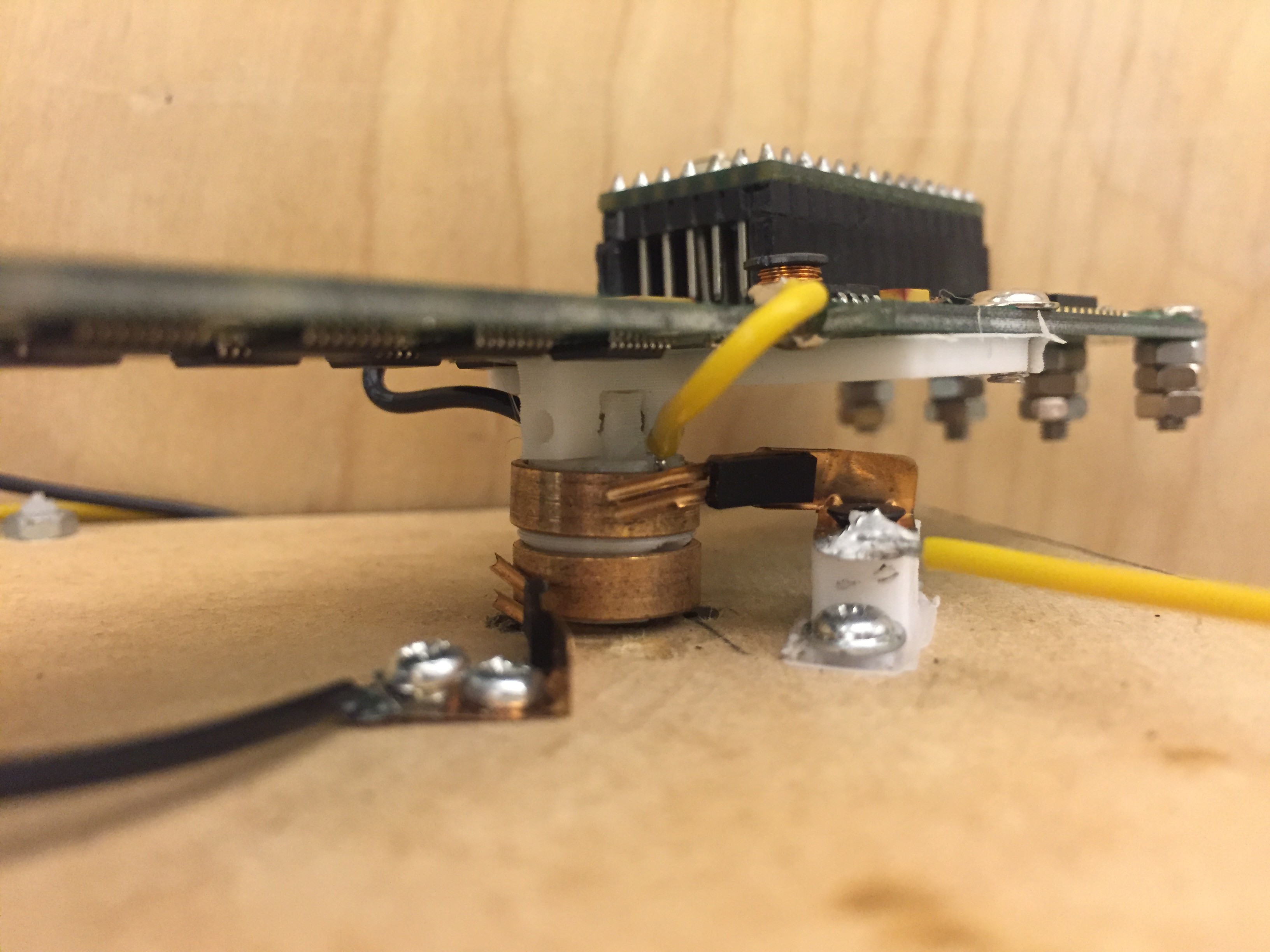
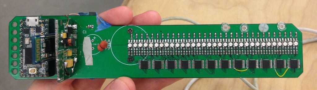
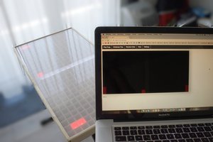
Check the logs and the picture to see what spino looks like.
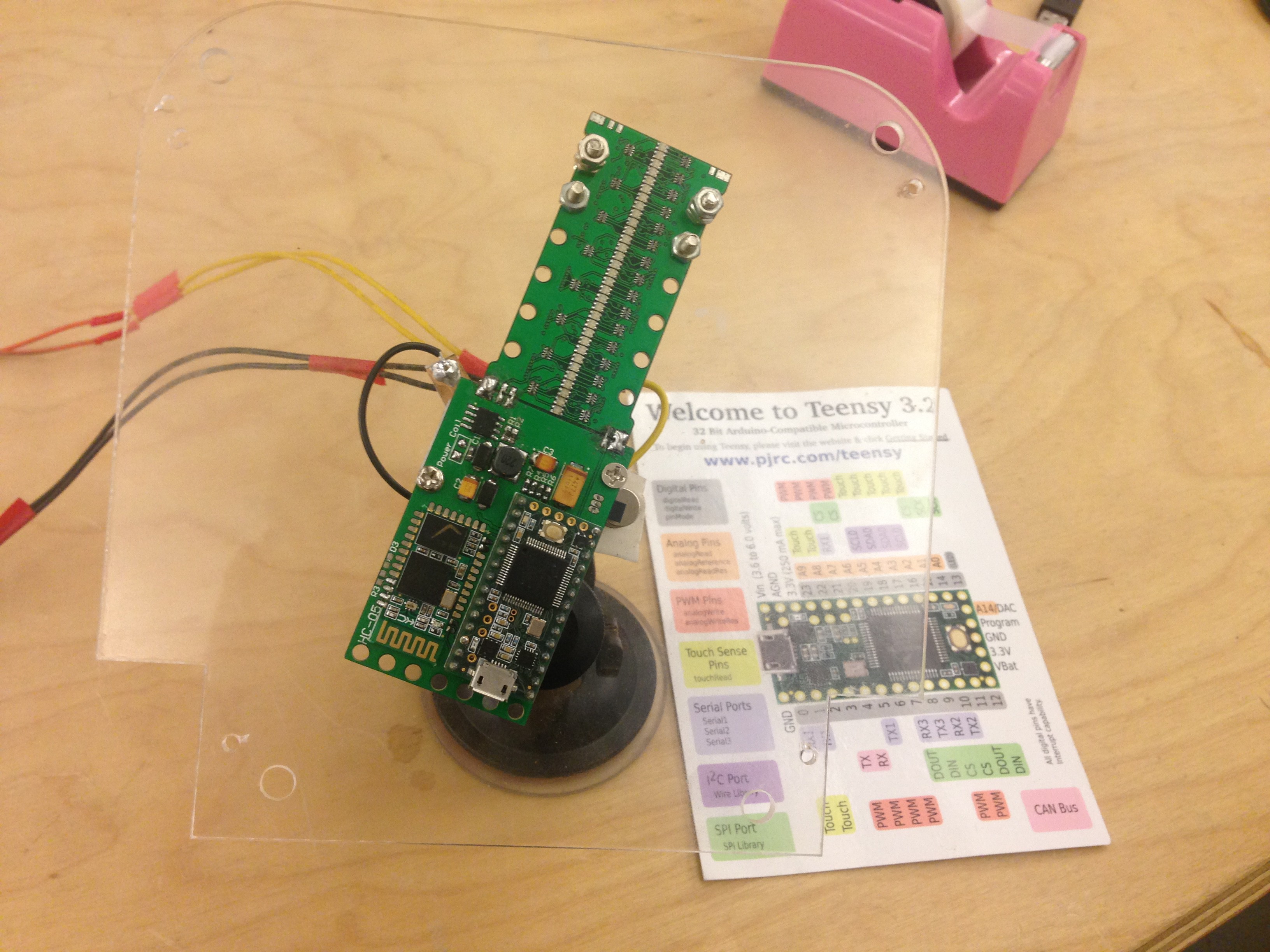
At this point it is still very experimental, we are trying to iterate on the design until we get something good. After that we also plan to build a nice casing for it.
We are based in Taiwan, so most of the components and PCB printing will be done either in Taiwan or China.
We'll try to keep a diary of our progress. Any feedback about our hardware design or cool new features / apps you could think of are welcome!


 caBattista
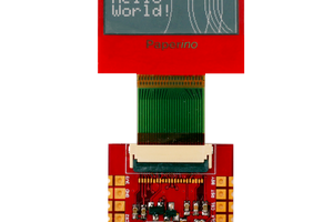
 Markus
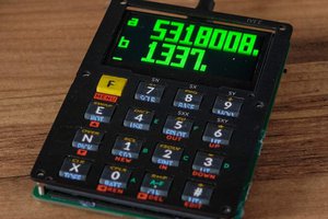
 svofski
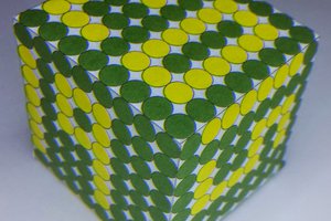
 daniel.bryand
Forgive the (s)pun but this is brilliant! Love it! I bet even my wife would love it! Don't forget to develop a V2.0 that'd be in 3D... Layered blades, as well as using the weird human eye perception of colors (green is "nearer", red is "further away"...)