Markus
The plan
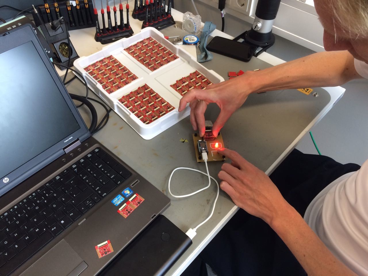
We got the first prototypes and the Arduino library going.
Now we want to make it available for all makers and electronics enthusiasts out there. Here we want to document our successes and failures in getting Paperino past the prototyping phase and in low volume production. If you want to pre-order a Paperino our just support us in our efforts check out our campaign on Crowd Supply.
But first let's take a deeper look into Paperino:
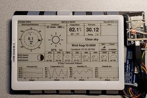
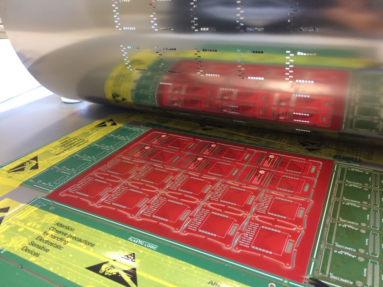
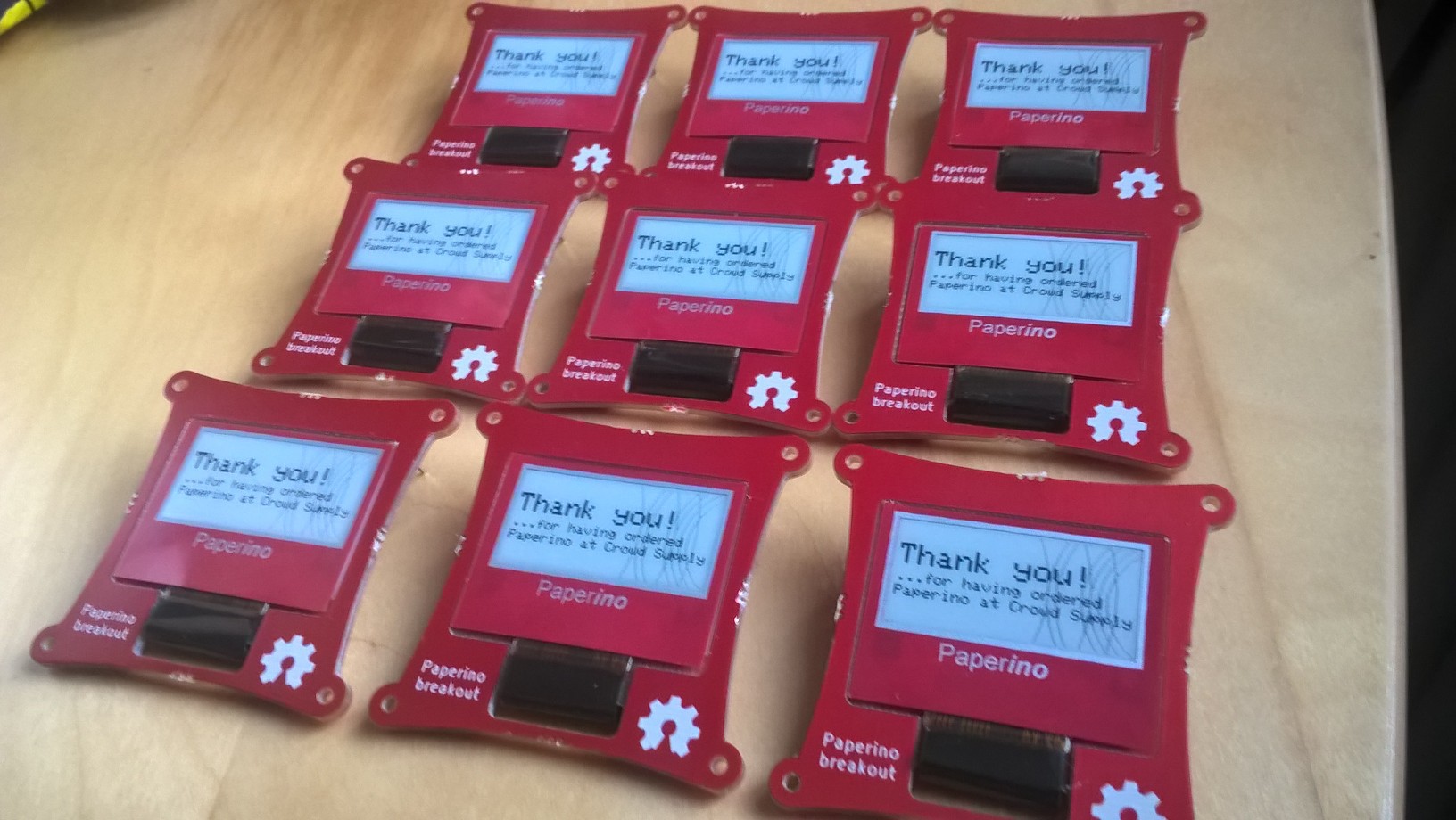
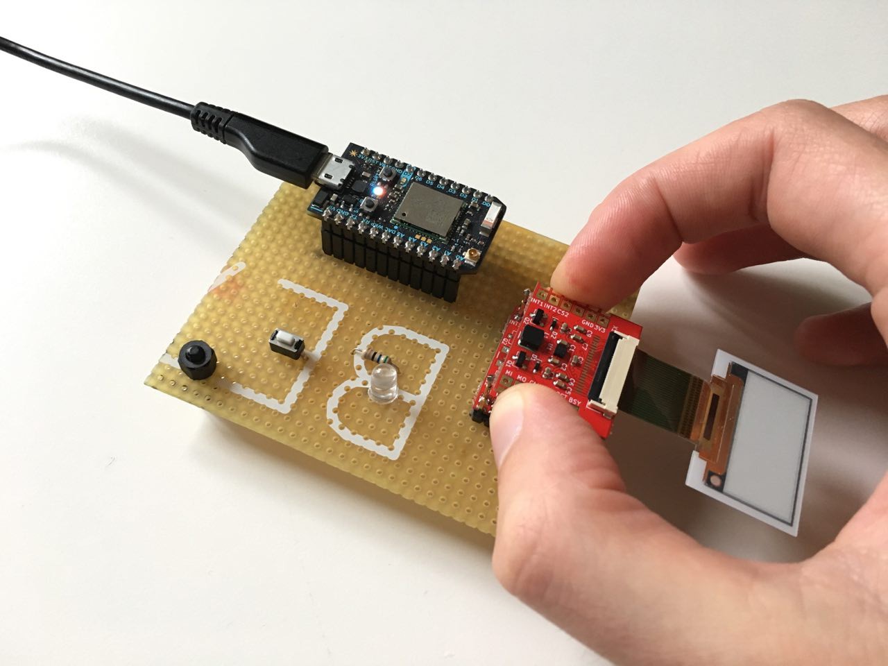
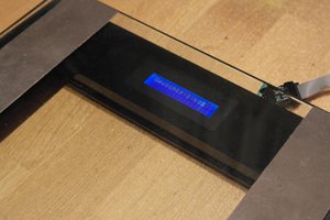
The display
We use a glass-free ePaper display from Plastic Logic. It weighs 1.2 grams and is only 0.5 mm thick (we're German so we use the metric system, sorry ;-)).
For those interested in the details here's some of the display's spec:
- Resolution: 148 x 70 px
- Pixel density: 150 ppi
- Grey levels: 4
- Weight: 1.2 g
- Thickness: 500 µm
- Power consumption: 4.5 mA (mean current for typical image update, update time ~0.8s)
- Operating conditions: 0°C .. 40°C
- Storage conditions: -25°C .. 50°C
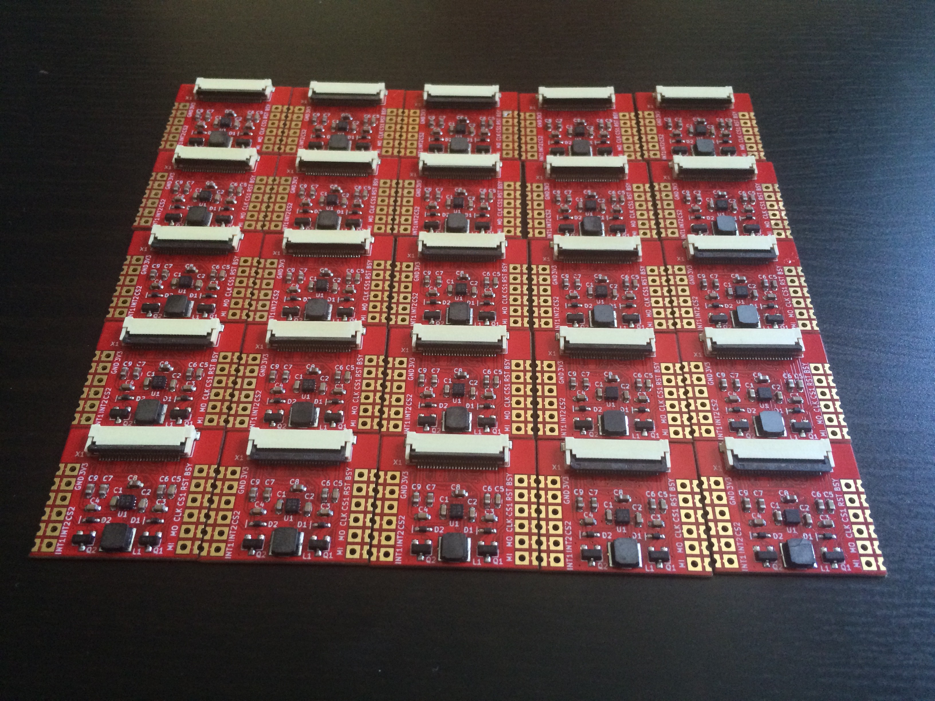
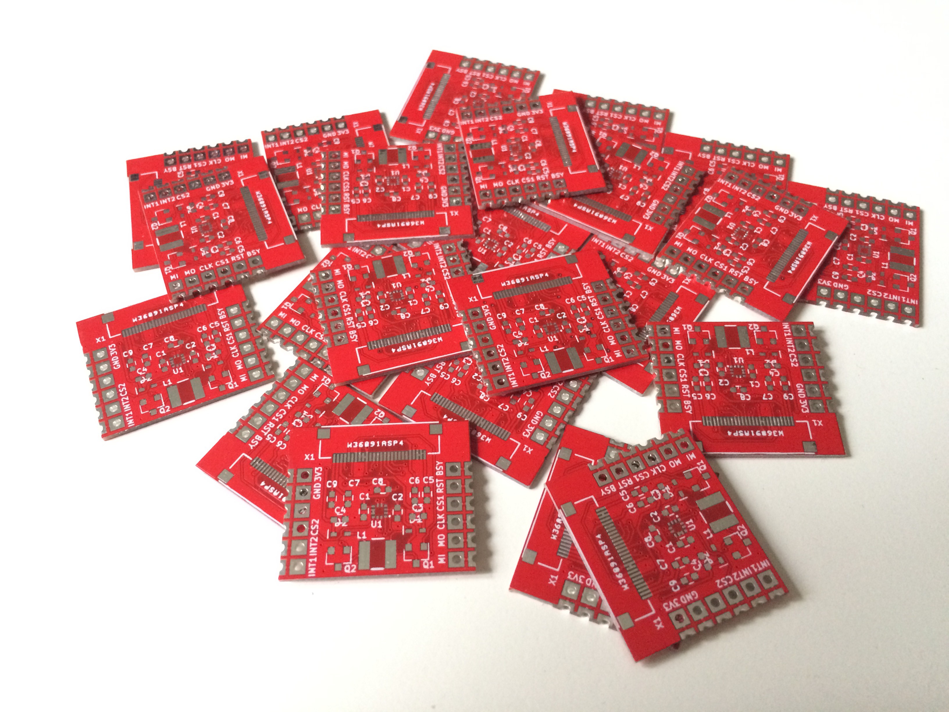
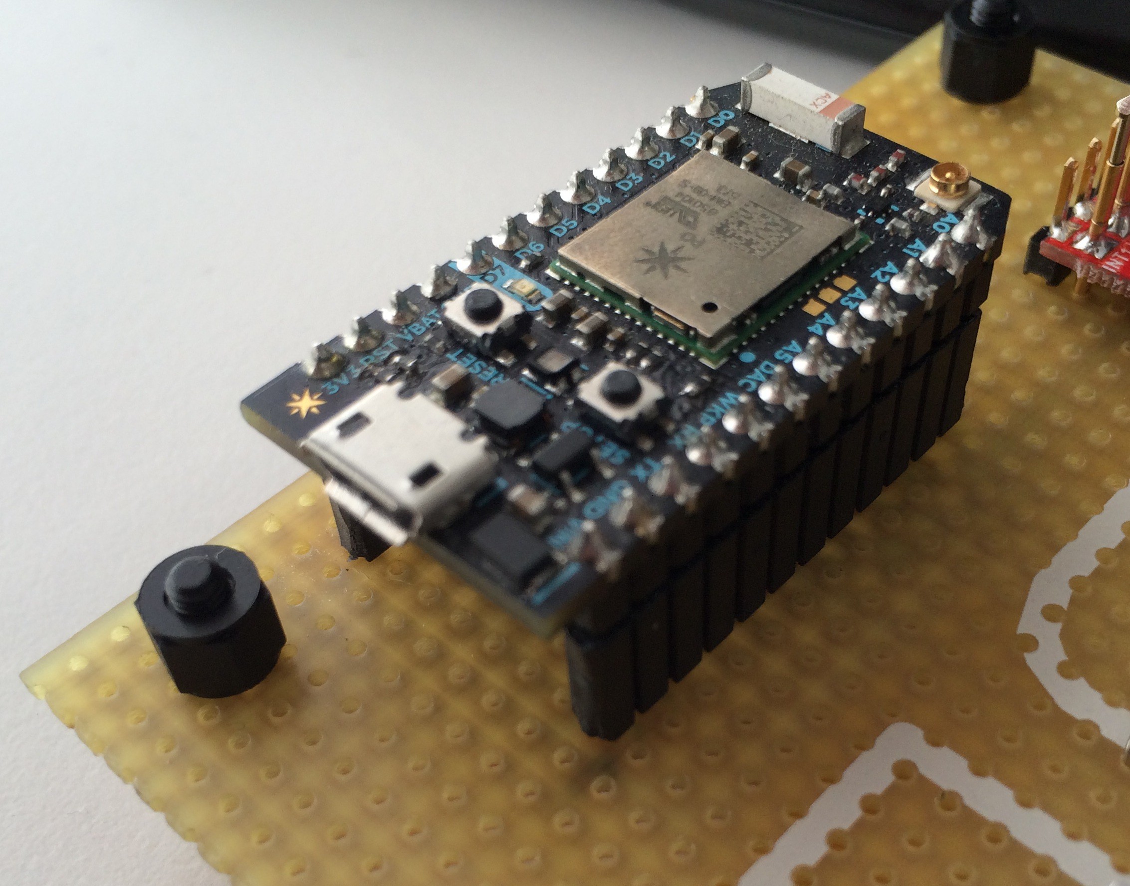
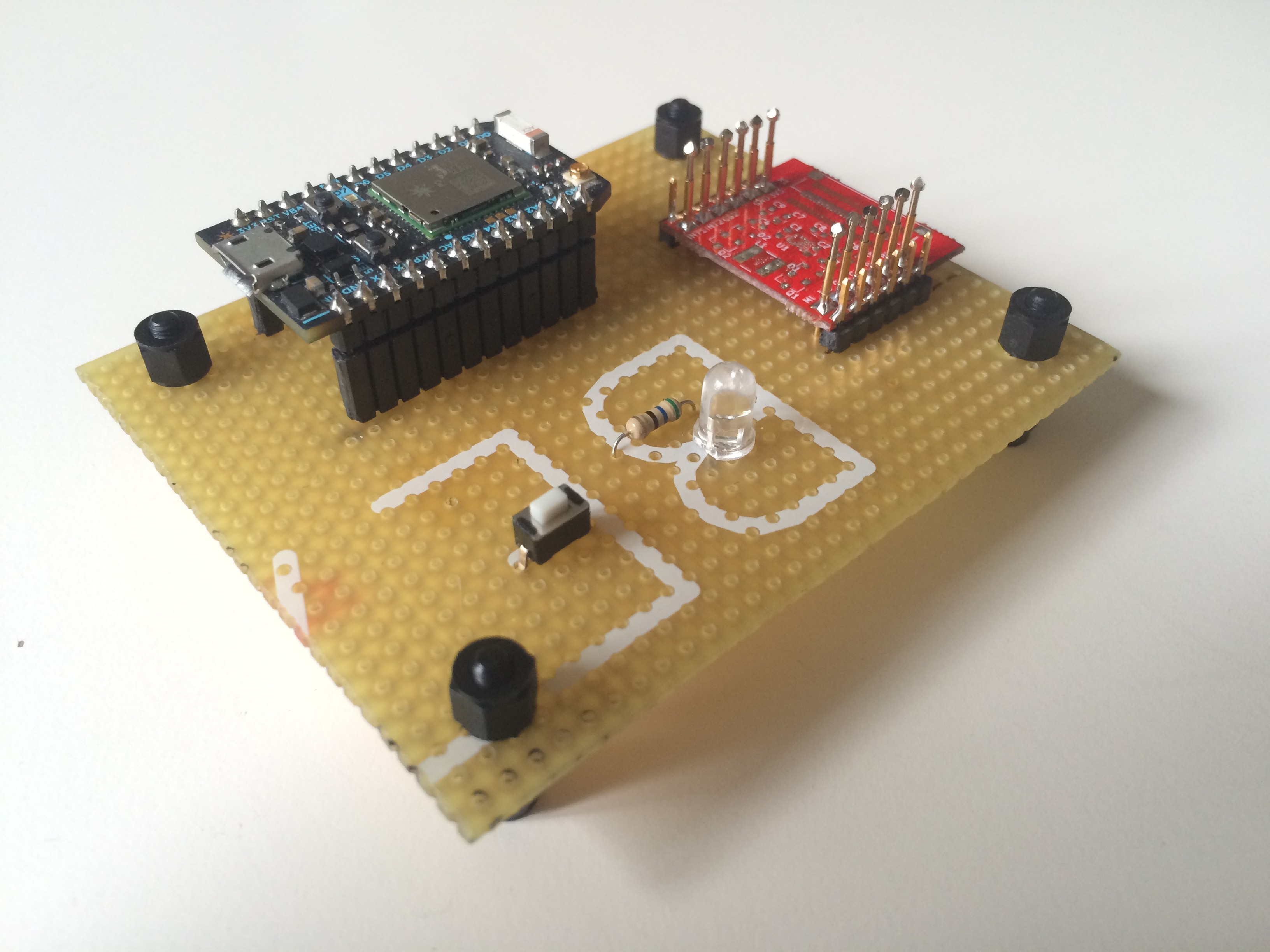
The drive module
The drive module is the heart and soul of Paperino (aside from the display, of course). It contains the booster circuit needed to generate the high voltages to drive the display (for those who want to know: we generate +17/-25 volts with the booster and the display's driver chip uses those to generate additional +/- 15 volts).
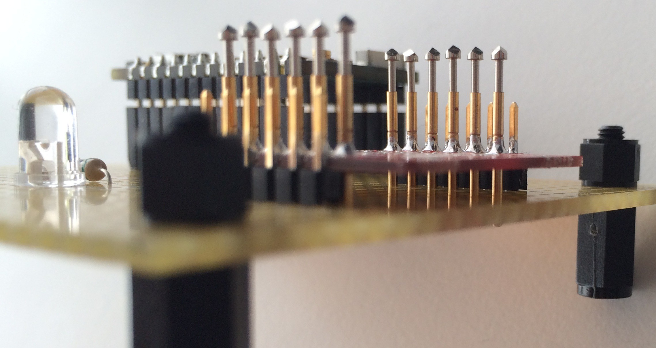
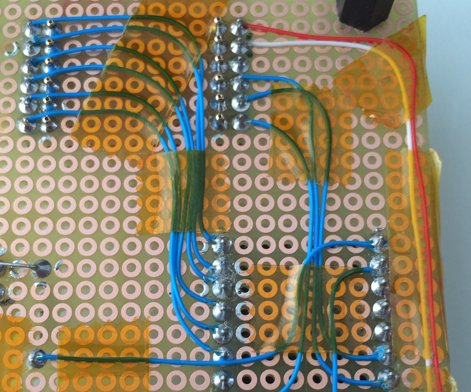
We use half-cut holes to mount the module to our shield and breakout board. You could use this module just like that for your next low power project. Just drop the module down, connect a display and you're good to go. The schematics and KiCad layout files are open source, so you could also check out our repository and do your own layout.
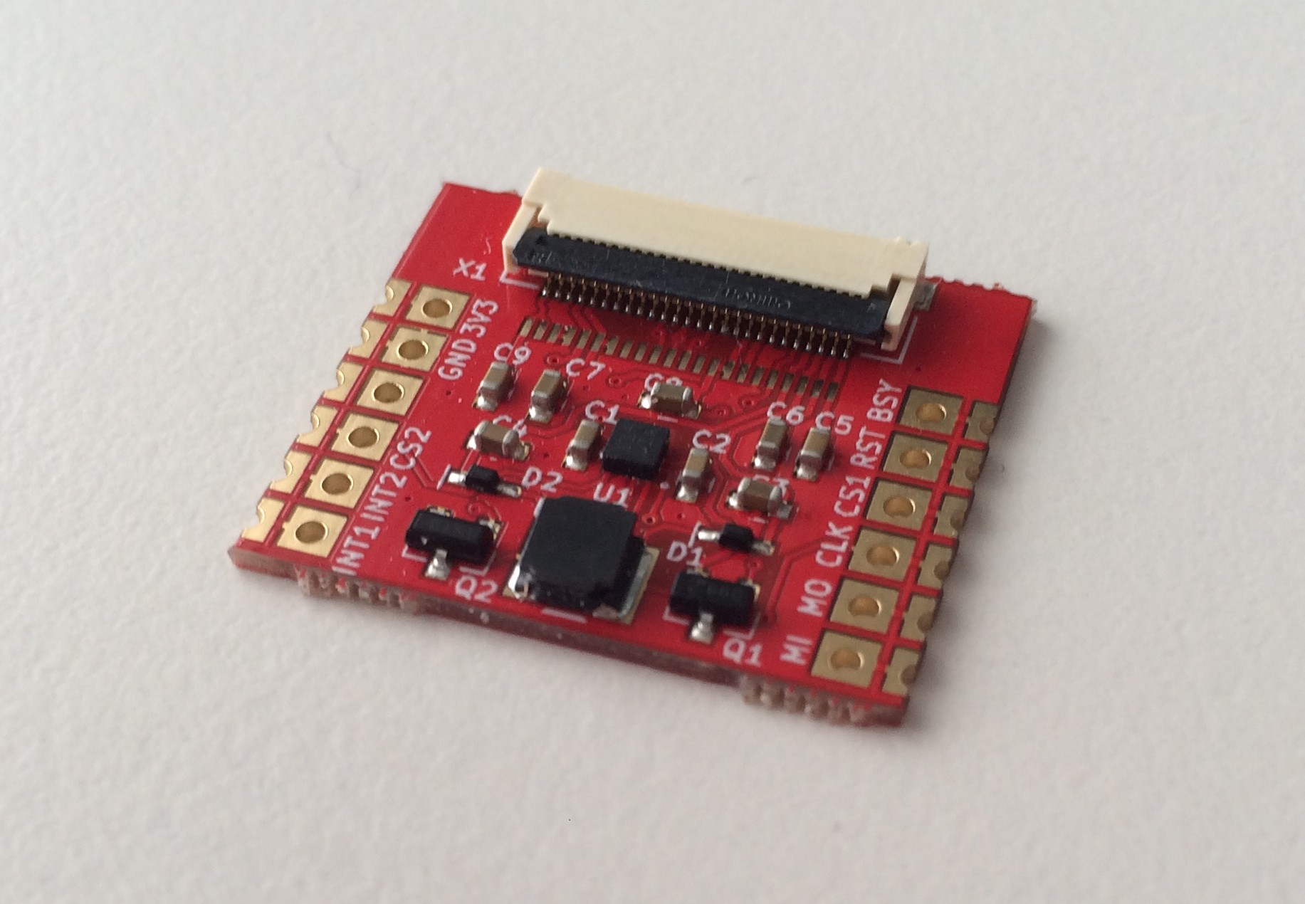
The module also sports an accelerometer for tap-sensing (a kind of touchscreen emulation, if you will).
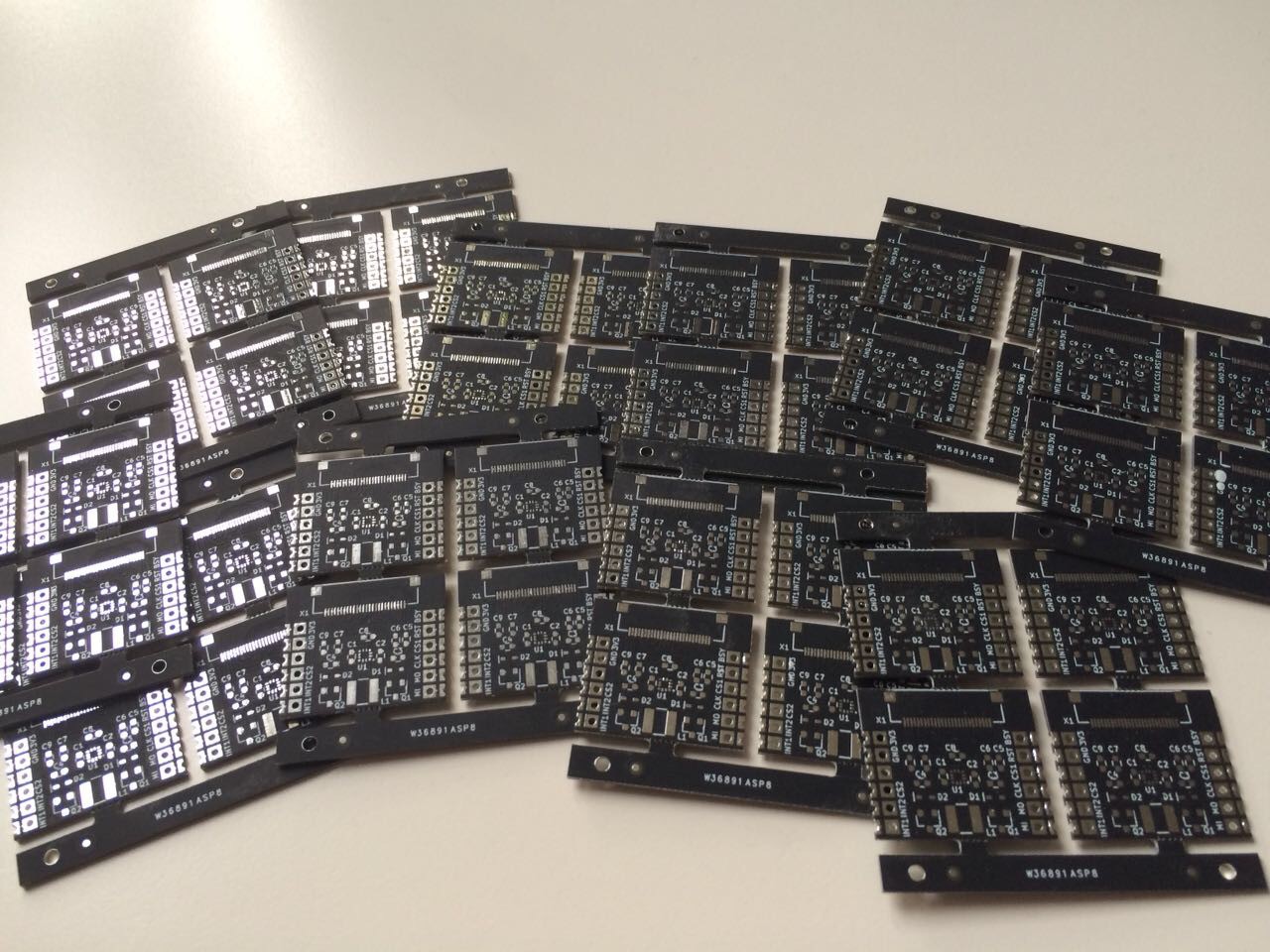
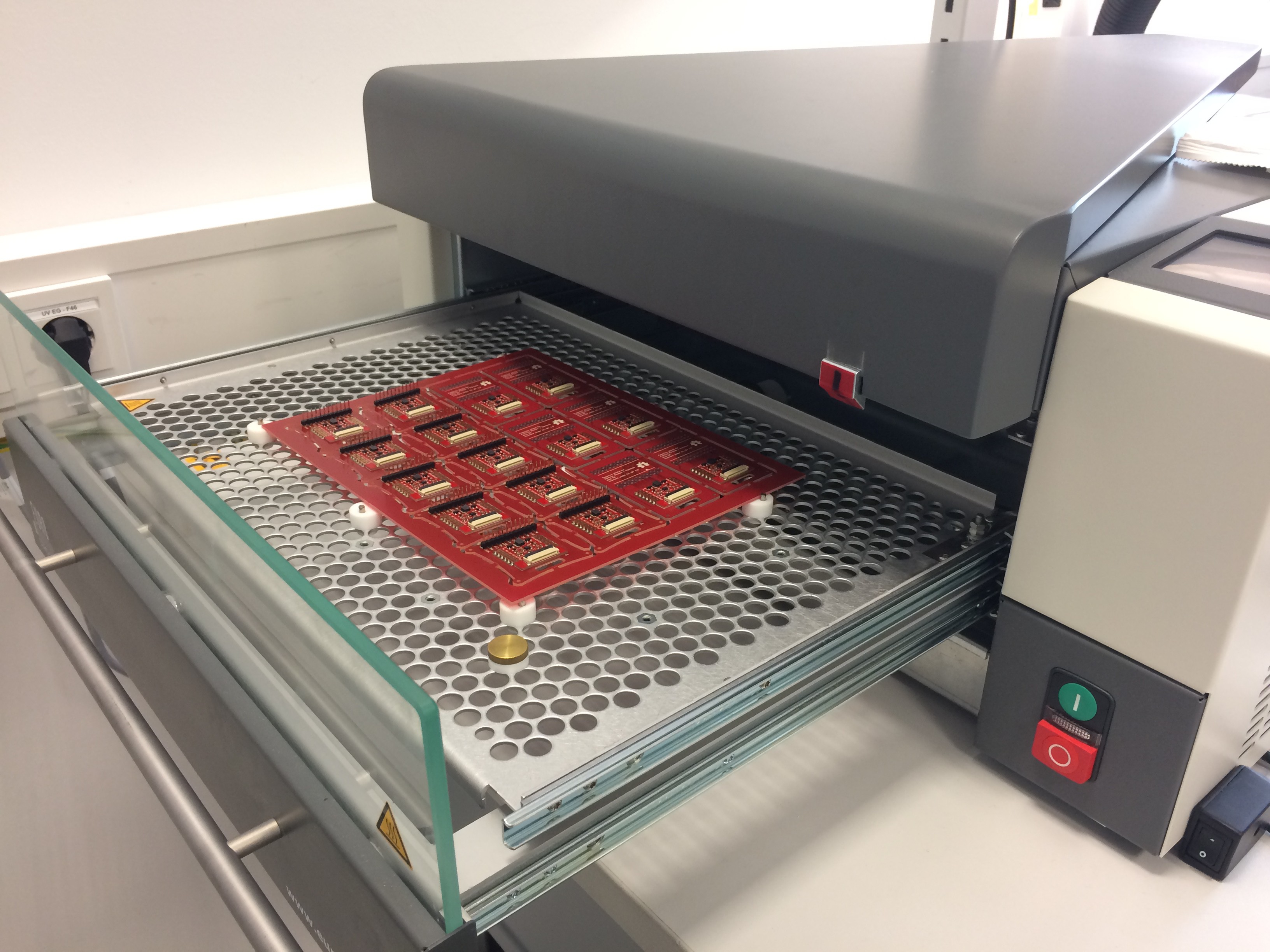
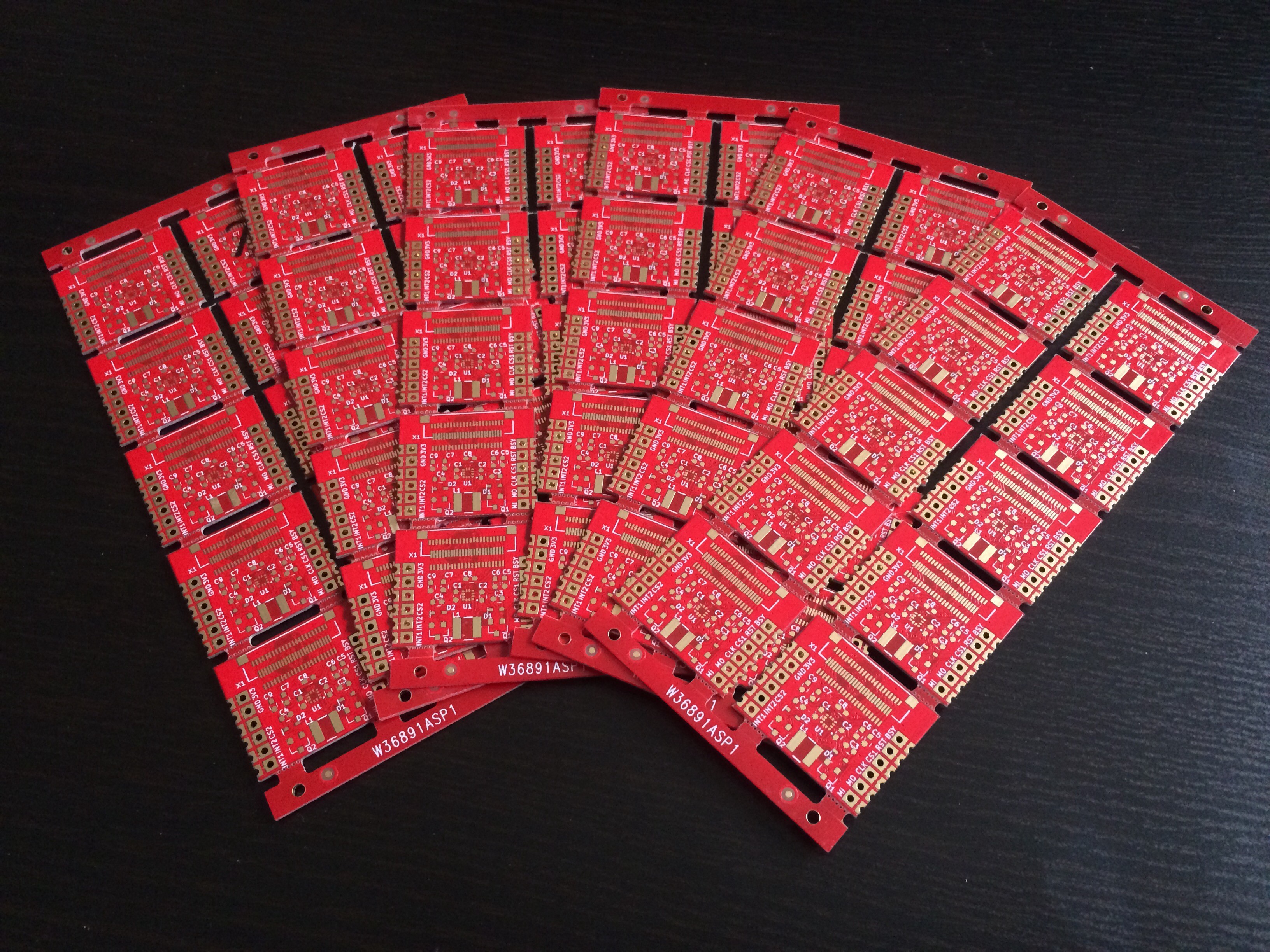
 Also the PCBs and connectors for the shield and breakout boards arrived. We decided to go with stacking headers for the shields, so you can plug several Particle shields together (we like to use the LiPo battery shield + our Paperino shield for example).


 Benjamin
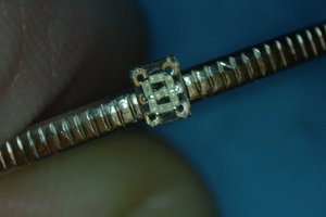
 Sam Ettinger
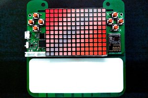
 deʃhipu