Close
0%
0%

Mid-air Laser Image Display

A screen-free mid-air image display using a ring of lasers and rotating mirrors

Similar projects worth following
The goal of this project is to create a mid-air 2D display. Previous 2D displays have been made using steam or fog as a projection screen for a traditional image projector, but this requires a difficult-to-generate fog projection plane. Using a ring of scanned modulated lasers, however, it's possible to approximate arbitrary light intensity distributions confined to a single plane in space. Any scattering material can then be used to make the display visible; there's no need to confine the scatterers to the image plane. With enough laser power, the scattering from air and suspended dust alone should make the display visible. With lower powered lasers, a uniform 3D scattering media (fog or smoke) should work.

This is a project I started back in 2013, but haven't found the time to devote to making it happen. To date, I've simulated the display and come up with a preliminary physical design, but have yet to build one. I was going to wait until I had some more progress to report before writing this up on hackaday.io, but I saw the string portraits on HaD, and figured this would be a good time to start documenting the project - it might just give me the kick I've been needing to start this effort back up.

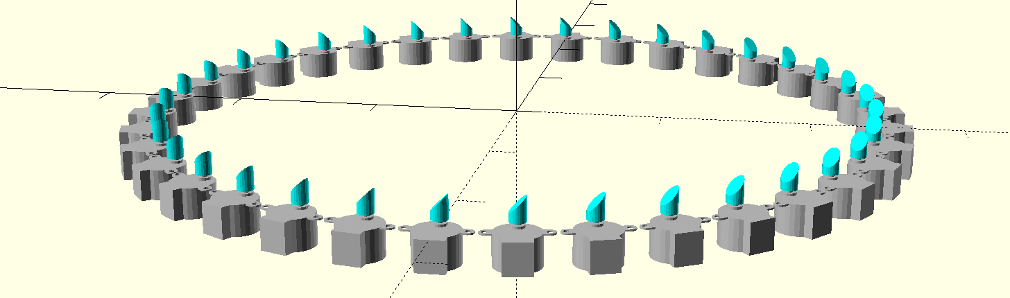
The idea is simple: a number of laser diode modules are fitted with simple motor-driven scanning mirrors. This would create a "sheet" of light from an unmodulated laser. When modulated, however, the laser can now produce a variable "fan" of rays. The rays from an entire ring of lasers overlap in a central circle, where the beams are scattered by the air, naturally occurring dust, or a volume of fog or smoke. When many beams overlap in an area, more light is scattered toward the viewer's eye creating brighter regions, thus forming an image. The contrast ratio of this device is limited by the number of lasers in the display; my simulations show that you could produce a usable display with a few dozen lasers.

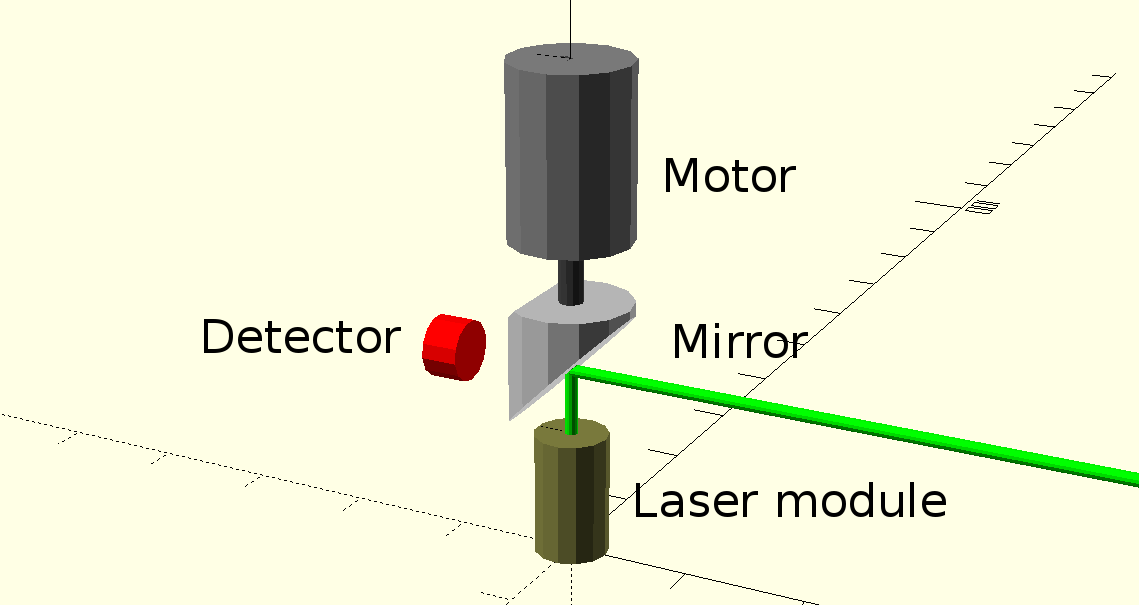
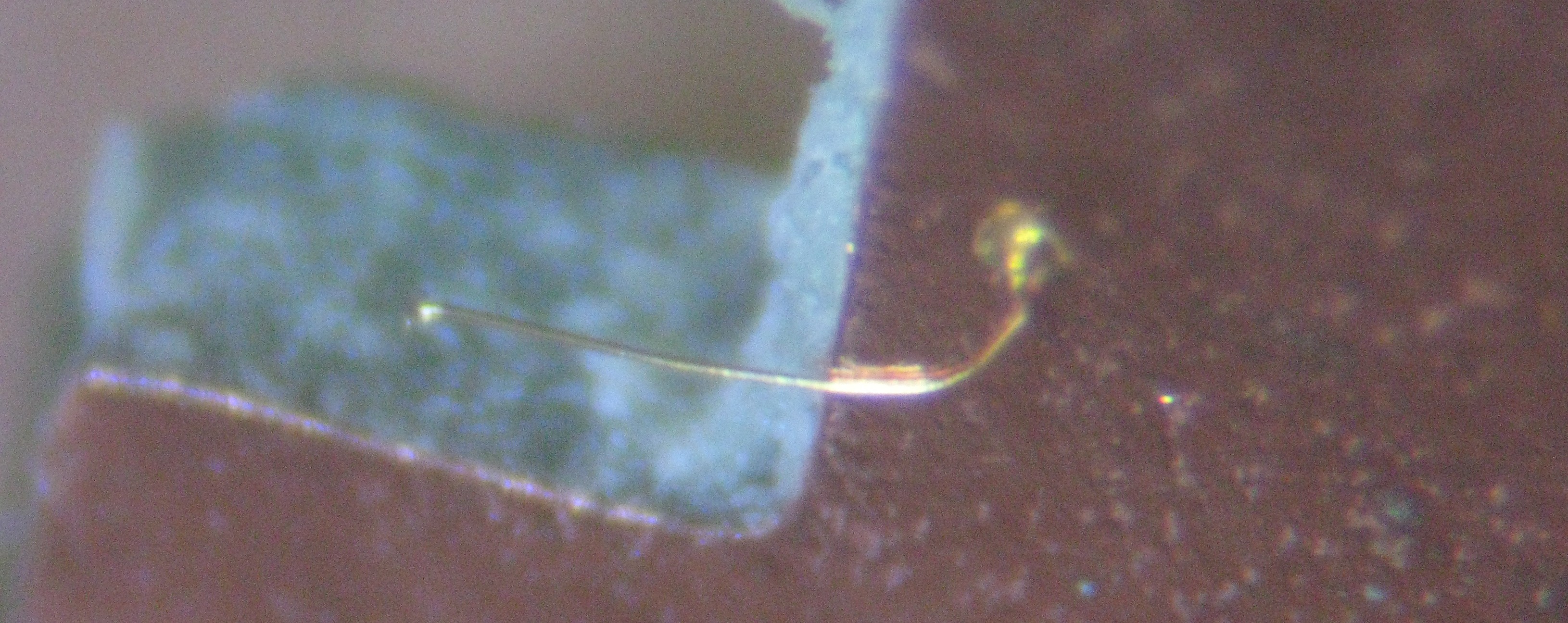
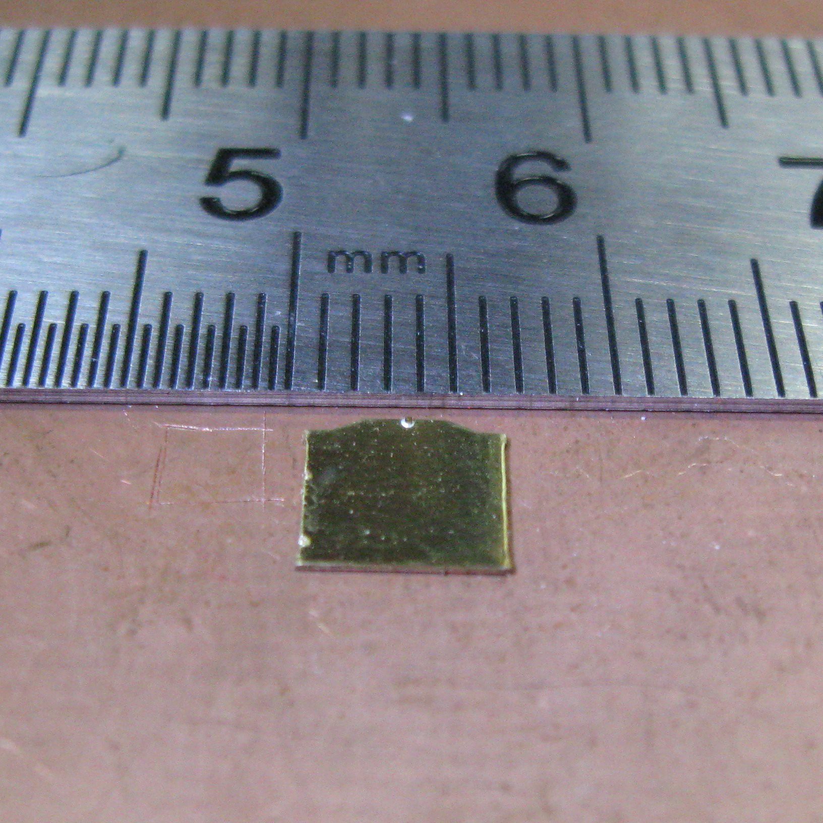
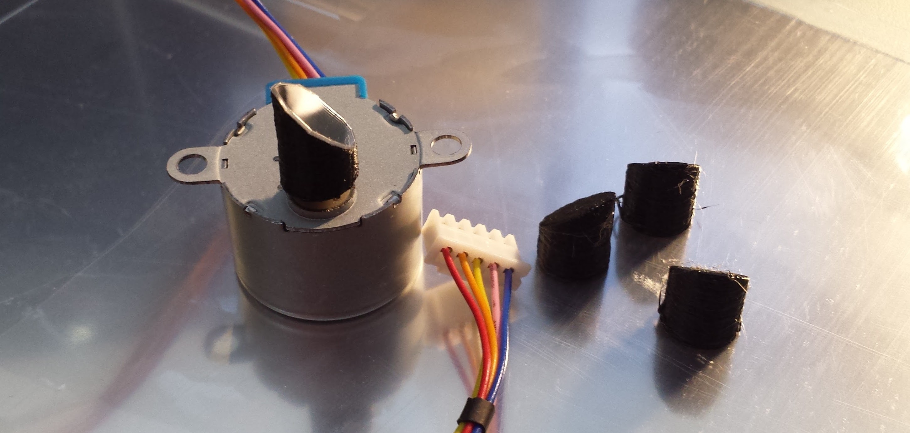
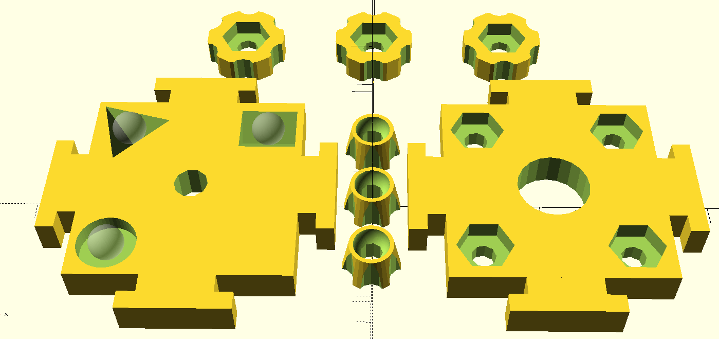
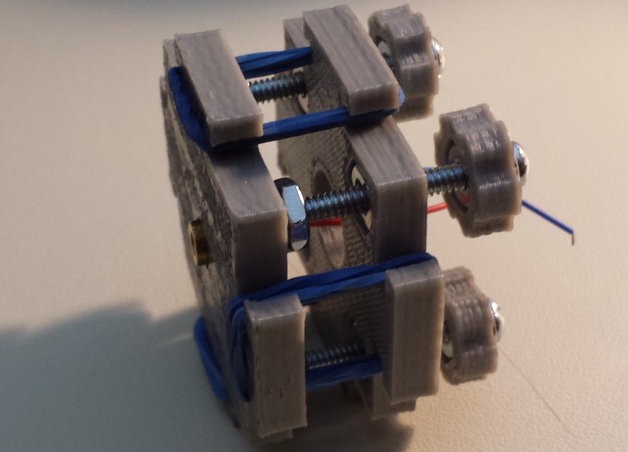
Here's a simple diagram of the proposed scanning assembly - one of these will be required for each laser. To scan the beam, a small motor (pager or micro quadcopter) is coupled to a 45-degree mirror. A photodiode senses when the beam crosses a reference position, so that software driving the laser diode modulator can synchronize the laser modulation with the motor. I envision letting the motors run freely, then using a software PLL to synchronize the data fed to the laser diode modulator (there's no need for the lasers to all be synchronized at the scan level).

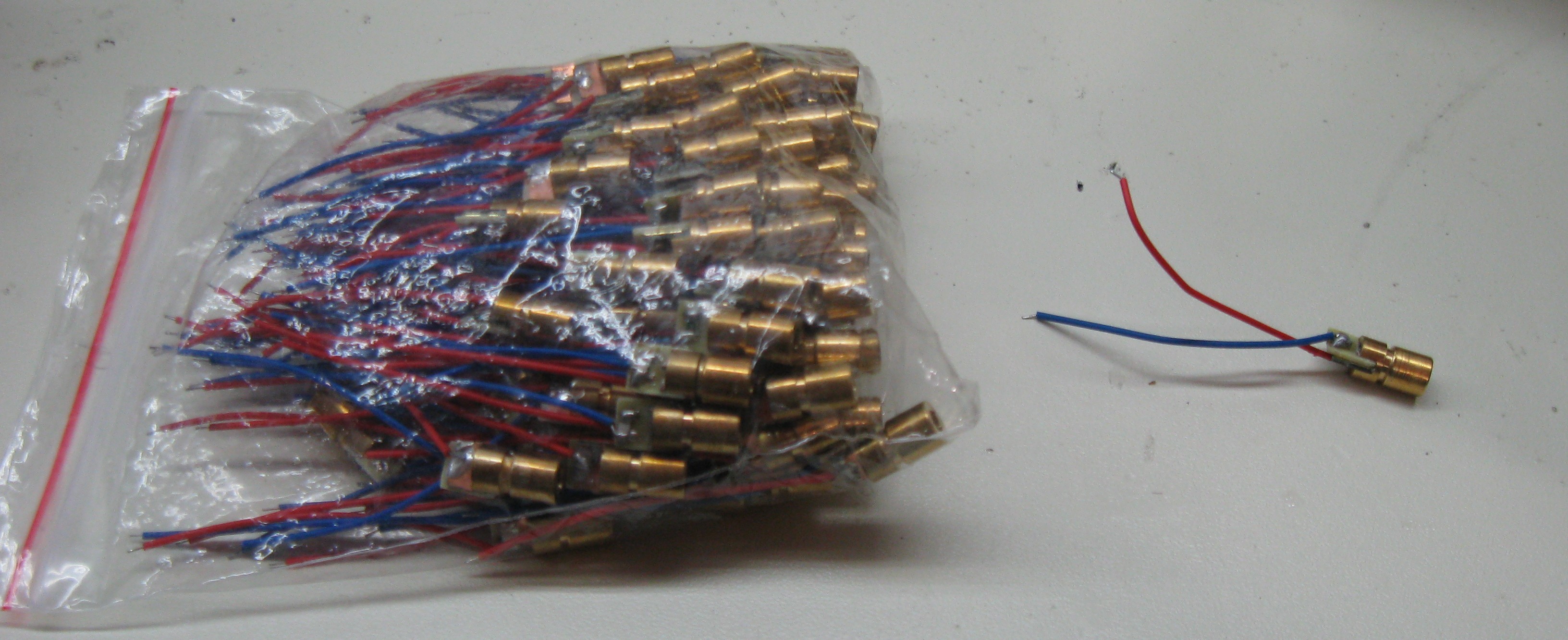
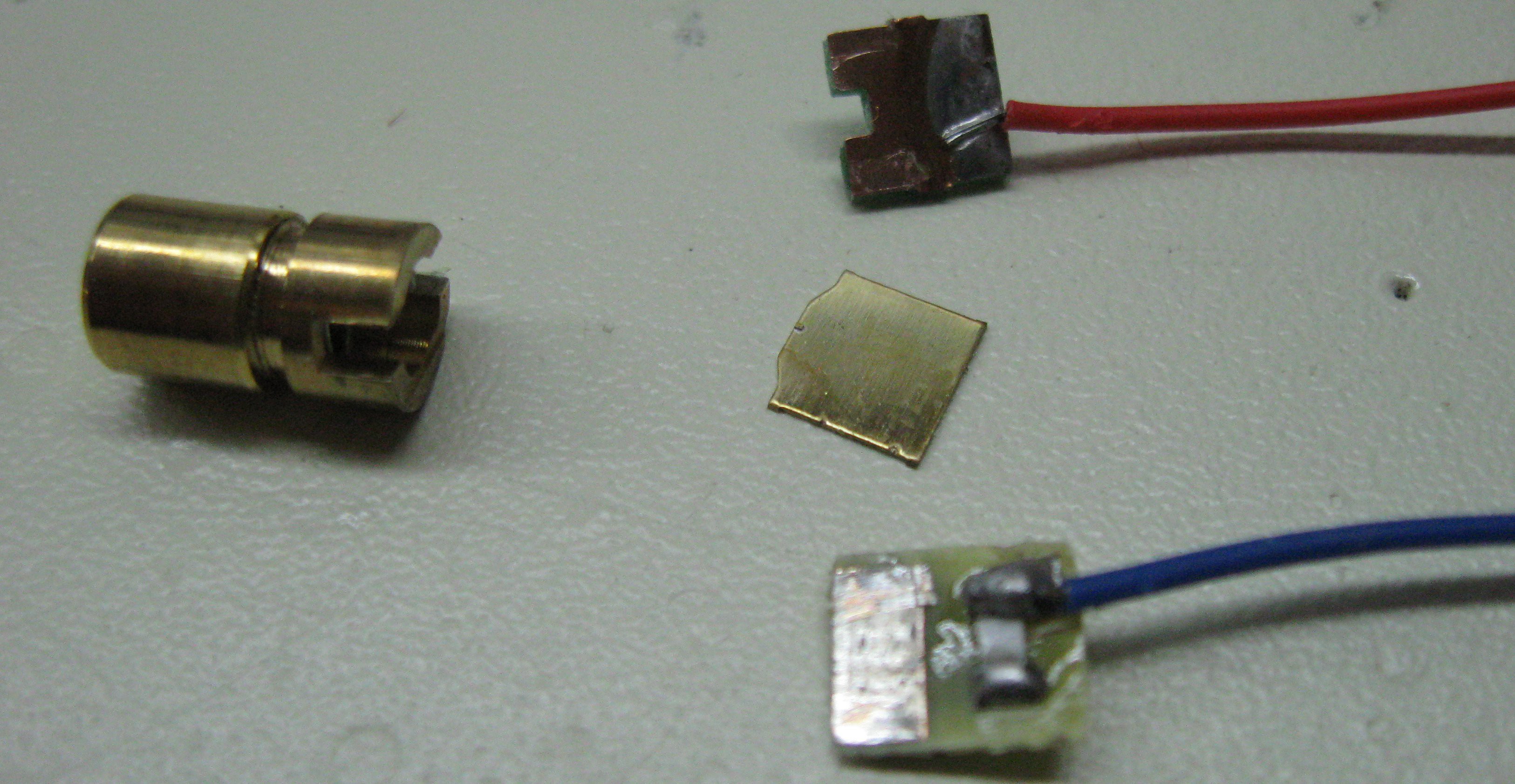
I picked up a hundred red laser diode modules cheap on ebay for a prototype. Although they're not very powerful, and the red color isn't great for viewing, I think I can make a workable prototype with them. Once I prove to myself that it's worth doing, I can invest in some doubled green modules, which are much brighter but more expensive.

Simulations

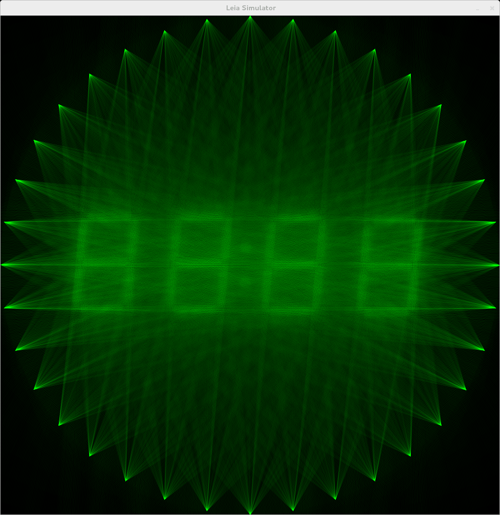
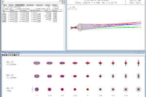
The simulator is interactive, and lets you load different test images and change the number of lasers and the number of angular positions scanned by each laser. Here's an example of an input image and the result with a 36-laser display (obviously, I was thinking of a clock mode):

Unfortunately, when I wrote the simulator in 2013, I used some code that I'm not free to open-source. Looking at it this morning, it uses an old (v1.2) SDL library, which isn't compatible with the new 2.0 version, so it needs a re-write anyway for further development. While I'm at it, I can re-implement the non-free portion so that the whole thing can be open-sourced.

The simulator uses a very simple algorithm to determine the intensity of each projected ray. Each ray path is traced through the target image, and the total sum image intensity along that path is recorded. This intensity is then used to set the projected ray intensity. You might recognize the back-projection algorithm from Computed Tomography (CT) scanning. The idea here is similar, although I haven't worked out a full treatment of the math yet. It's quite possible that the quality of the images could be improved by applying a proper filter to the target image, similar to the filtered back-projection algorithm used in CT.

  • Cheap Laser Diode Module Teardown

    Ted Yapo08/08/2016 at 17:35 0 comments

    I found some red laser diode modules on ebay for the prototype. They were $0.285 each (qty. 100), which sounded really cheap - let's find out why. EDIT - I bought these in 2013; you can currently find them for $0.19 each on ebay with free shipping.

    Here's the lot of them and an individual unit (6mm barrel diameter):

    After destructively testing one of them electrically (details to come in the next log), I pulled it open:

    The brass barrel contains a lens press-fit or secured with adhesive (I didn't take it out). Stuffed into a slot in the barrel is a sandwich of two fiberglass PCBs around a brass sheet with the diode die bonded to the top. When the diode was still intact, you could see the tiny gold bond wire attached to the top of the die. It remained with the positive PCB after disassembly:

    I was actually quite surprised to find there was no encapsulation whatsoever; you could reach in (with a toothpick) and touch the die and bond wire. The board connected to the negative lead contains a series resistor measuring 33.2 ohms; this is intended to let you run the laser from a 3V DC supply - another surprise: no photodiode feedback, and no constant current driver. When I first played with laser diodes (780nm IR) in the late 1980s, they were finicky things, requiring special optical-feedback driver circuits for protection from over-current. Either they've improved substantially since then, or these diodes are destined for an early grave.

    Here are some zooms of the die on the brass shim. It's probably bonded with conductive adhesive similar to that used to bond LEDs (see the Sparkfun Tutorial about how LEDs are made).

    I've measured the I/V curve and optical output for one of these modules, and am working on a simple, fast, driver design. I'll present both next time.

  • Slow-Scan Prototype

    Ted Yapo08/04/2016 at 02:37 0 comments

    I think one of the reasons this project originally stalled was the daunting prospect of the mechanical design. Synchronizing code with precisely aligned mirrors spinning at high speeds doesn't sound easy. Of course, the way to attack such a problem is to break it into pieces, which is what I've been doing recently. I've decided for the first prototype to slow everything way down - below the flicker fusion rate - into the seconds-per-refresh region. Of course, the eye will no longer perceive the rendered image, but it can be captured in a long camera exposure. I've routinely done exposures of tens of minutes with a DLSR for astrophotography (too much stray light around here for much more), so a few seconds will be easy. The system won't be usable for a display, but I'll learn a lot about what it will take to make a real one, and prove (beyond simulation) that image formation is possible in this way.

    While high-speed motors would be required for a "live" system, a slow-scan approach allows the use of cheap stepper motors to drive the mirrors. I made a low-ball offer on (40) 28BYJ-48 geared stepper motors on ebay, and it got accepted, so I'm going to go with those. I have a few of them from other projects, and I know they have their issues, especially backlash in the gear train. Of course, I'm only going to drive them in one direction at a constant speed, so I don't expect too much trouble.

    I designed a simple mirror mount in OpenSCAD and printed a few that fit tightly on the motor shaft (pictured above). I was lucky enough to find some thin polycarbonate mirrored sheets on Amazon. They're self-adhesive, but it doesn't stick particularly well, and probably won't work for the real system, but it seems good enough for a slow-scan prototype. The quality of the reflection is surprisingly good - once attached, the mirror isn't exactly flat, so it distorts a laser pointer beam a little, but it's probably good enough. I cut the first rough elliptical mirror with scissors, but I may end up just making round ones with a chassis punch.

    I decided to go with 36 lasers in the first prototype. Here's an early sketch of the possible layout - it's 500mm in diameter. The large size of the motors makes the ring larger than I really want, but I'm going to accept it. So far, I'm thinking of cutting a frame from medium-density fiberboard.

    The last piece of the scanning mechanics is the laser mount. I'm still not sure if a simple 3D-printed interference-fit mount for the LD module will work, or if I will need to provide adjustments for aligning the laser. I have a design for a 3D-printed kinematic mount I made a while back that might be useful. It uses acorn (cap) nuts on 3D printed bearing surfaces.

    In its current form, it's a bit large to incorporate into the display design, but I've printed a few of them, and they make decent precision alignment stages for laser diode modules:

    I looked into using steel or glass inserts for the bearing surfaces, but I couldn't find anything suitable (and cheap). Acorn nuts on ABS or PLA seems to work OK, at least for light-duty use.

View all 2 project logs

Enjoy this project?

Share

Discussions

Rolf wrote 01/03/2024 at 23:26 point

Doesn't seem to be moving forward. I hope you're well and you are busy somewhere else.

Is this your Display?

https://youtu.be/Hg2Jjq02db0


  Are you sure? yes | no

Esteban wrote 09/13/2019 at 02:05 point

Quite the interesting project! Did you make any progress since 2018? 

  Are you sure? yes | no

helge wrote 04/13/2018 at 14:27 point

That's the kind of project I'm here for :)

  Are you sure? yes | no

Ted Yapo wrote 04/13/2018 at 18:21 point

Yeah, if I can just motivate myself to build the first prototype, the rest should be easy:-)

  Are you sure? yes | no

helge wrote 04/14/2018 at 18:12 point

if only they made MEMS spatial light modulators... :)

  Are you sure? yes | no

Ted Yapo wrote 04/14/2018 at 19:33 point

@helge I drool over DLPs from time to time, but the price never seems to drop.

  Are you sure? yes | no

helge wrote 04/14/2018 at 20:02 point

on the cheaper side, there are piezo bimorph and trimorph actuators.

https://www.steminc.com/PZT/en/piezo-bimorph

They also make them with resonant flaps for fan applications :) I imagine one could as well find a way to attach a very small mirror and spring to the basic actuators to get 100-200 Hz resonant motion.

https://www.steminc.com/PZT/en/piezoelectric-fan-blade-60-hz

If you're really cheap you might want to consider sticking a small triangular acrylic prism onto a small motor shaft :D

  Are you sure? yes | no

Lee Cook wrote 12/02/2016 at 14:07 point

Have you considered just having, rather than multiple motor drives, all the mirrors on a shafts through bearings with the same size timing pulley at the bottom?  That way, you could drive them all with a timing belt from a single motor, and they'll stay in sync.  Position sensing could be centralised to a single pully on the loop.

  Are you sure? yes | no

Ted Yapo wrote 12/02/2016 at 14:23 point

It would be convenient to have everything mechanically synchronized - but the practicalities of what I can cobble together are the problem.  I think I can design 3D-printable mounts for the motors and lasers and mirrors that might take a little tweaking (adjustment screws) to get aligned.  If I can get that to work, I just need to print a bunch of them to get the prototype going.

Having made a first proof-of-principle would be some good motivation to think about improved mechanical arrangements :-)

  Are you sure? yes | no

Lee Cook wrote 12/02/2016 at 14:31 point

I've not put a huge amount of thought in to it, but I would have thought the overall 3d printed mounting arrangement would have been the same, just replacing the motor with a pulley gear.  You could still do the alignment teaking then tighten the grub screw in the pully when it's pointing at the right angle.

  Are you sure? yes | no

Mike wrote 11/28/2016 at 16:28 point

for the laser sweep .. rather than individual rotating mirrors, you could have a "carousel" of cylindrical lenses that sweep in front of the lasers .. then you have one motor.  If the lenses are at the same angular pitch as the lasers, then the lasers will be automatically synchronized .. and if you have, say, 100 lasers (and 100 lenses) the carousel can turn pretty slowly.

An alternative might be faceted mirrors on a gear assembly. 

  Are you sure? yes | no

Ted Yapo wrote 12/02/2016 at 14:18 point

I originally envisioned a line-array of lasers rotating around the display like an MRI machine - then I remembered that my mechanical fabrication skills and resources are primitive compared to experience with software and circuits.  So, a software PLL seems more within reach than complicated mechanical designs.

I like the notion of multiple cylindrical lenses, though - and the fact that the rotation can be slow.  For a scaled-up design, it might make a lot of sense.

  Are you sure? yes | no

Ted Yapo wrote 12/02/2016 at 14:25 point

Actually, maybe a line of lasers rotated around on a lazy-susan bearing would be OK for a long-camera-exposure pre-prototype experiment.

Wow.  I need to think about that for a little bit.  Maybe a single stepper could do it - it seems like the quickest solution to a first actual test.

  Are you sure? yes | no

Similar Projects

Does this project spark your interest?

Become a member to follow this project and never miss any updates