0%
0%
RetroRiter
A Pi Zero based desktop computer with attached thermal printer.
 James
JamesBecome a Hackaday.io member
Already have an account? Log in.
Just one more thing
To make the experience fit your profile, pick a username and tell us what interests you.
Pick an awesome username
hackaday.io/
Your profile's URL: hackaday.io/username. Max 25 alphanumeric characters.
Pick a few interests
Projects that share your interests
People that share your interests
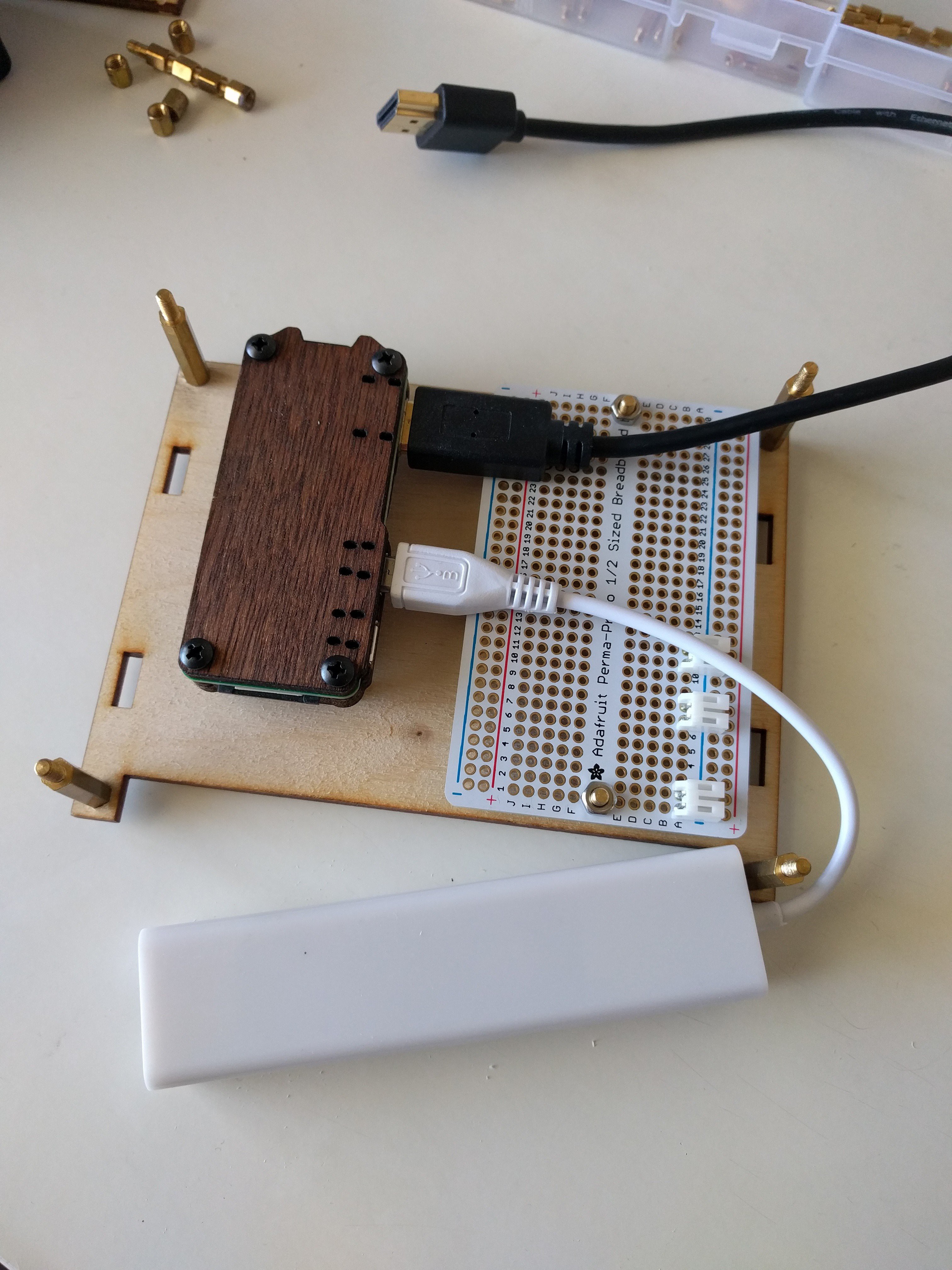
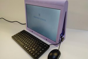
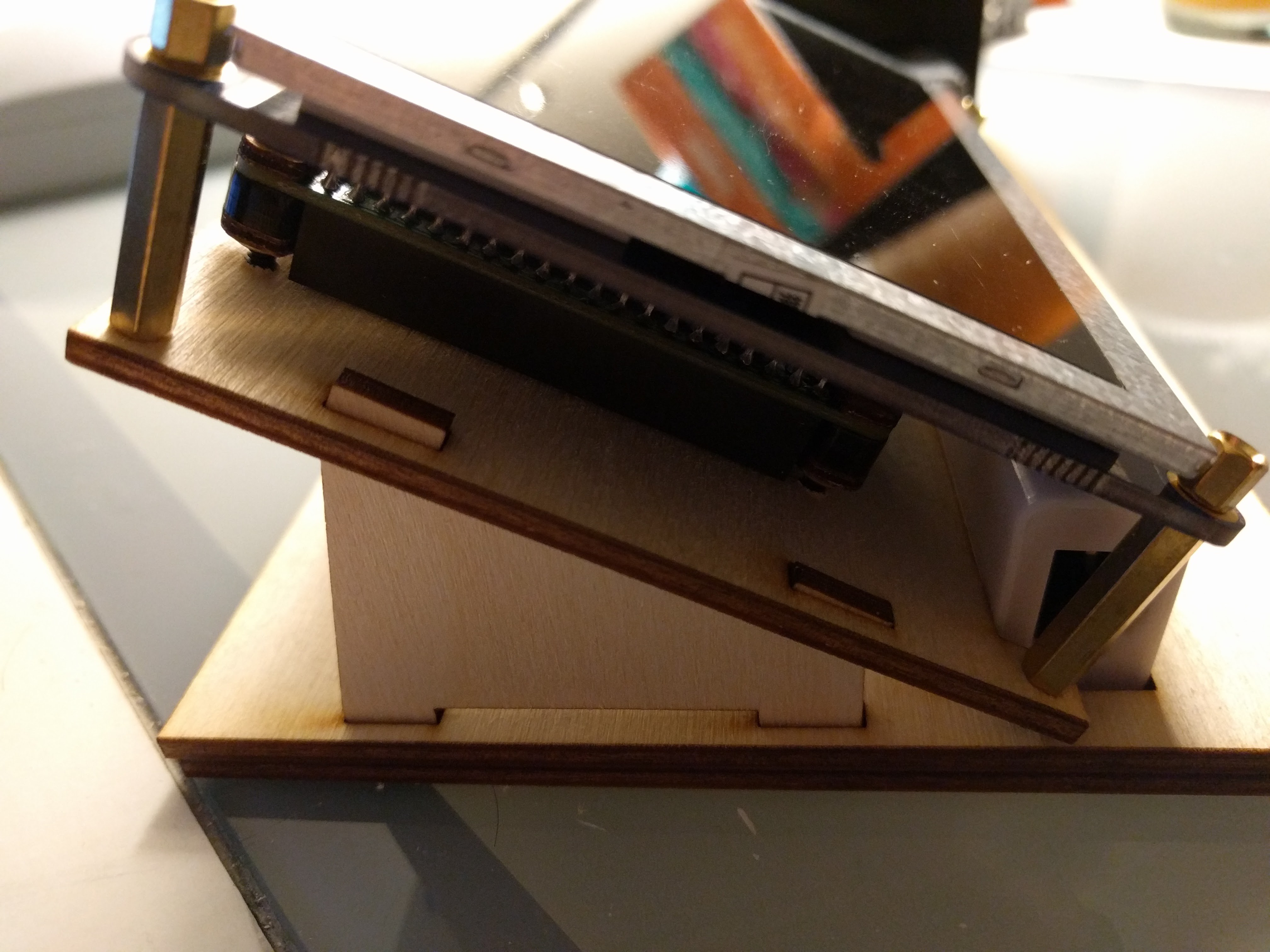 You can also see the Pi Zero in its place.
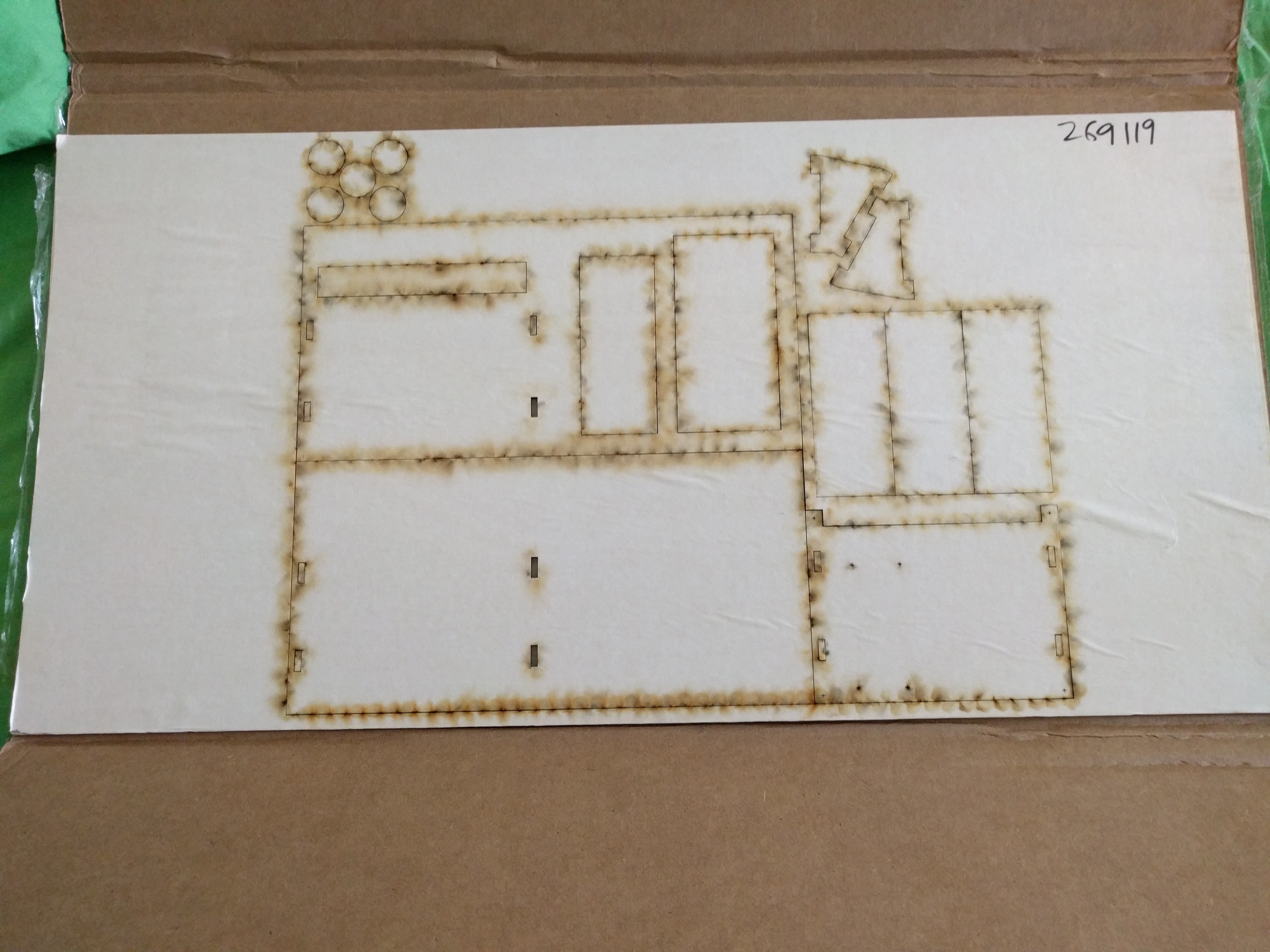 Burn marks everywhere!
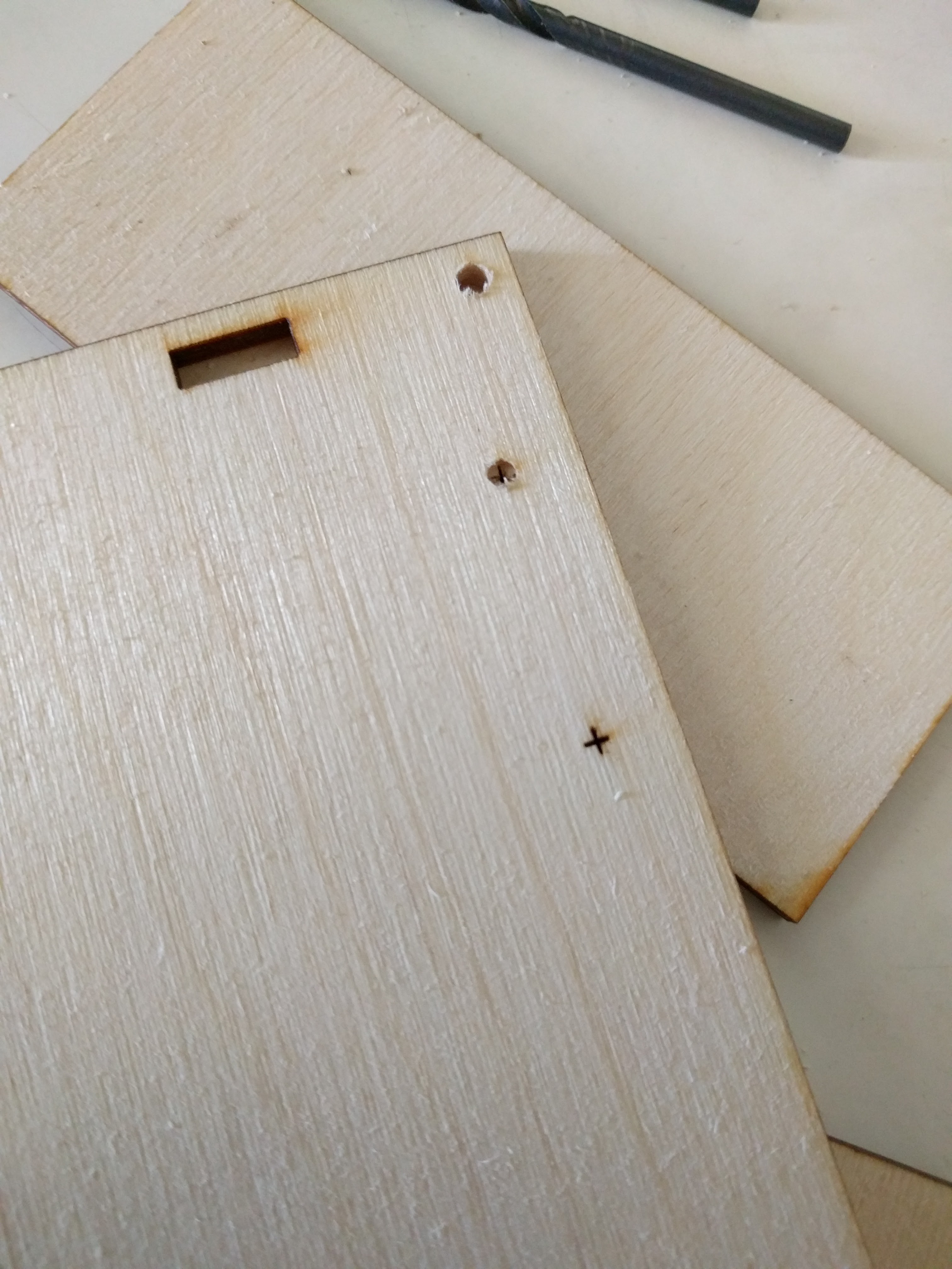 I had also been worried about the thickness of the material (which is 3.2 +/- .3 mm) and how that would work with the LCD support brackets, one slot which you can see above. I made them slightly bigger than 3.2mm, and everything fit just fine. I'll have to shim / glue it for it to really be secure, but that's not a big deal.
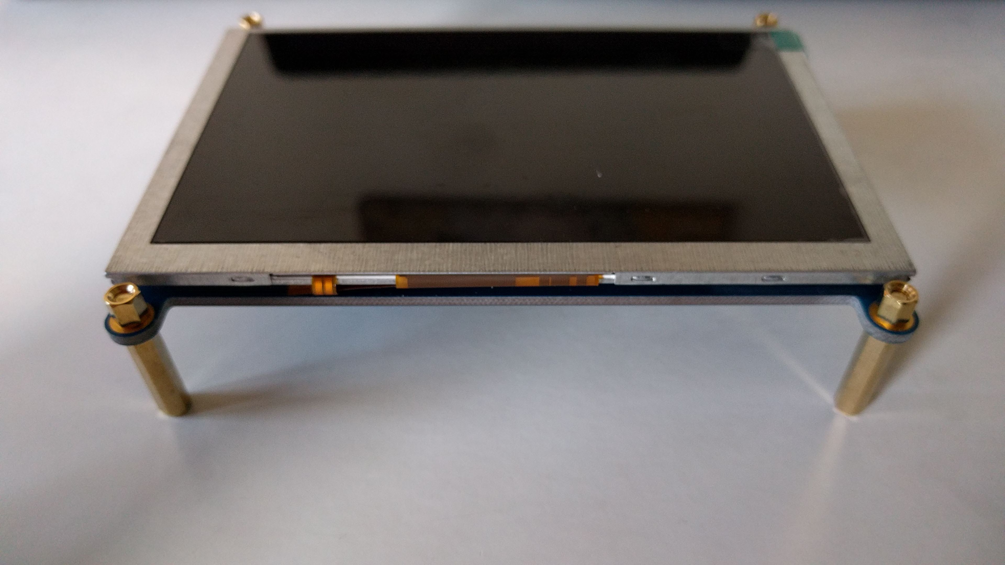
 Neil Lambeth
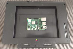
 Dan Jilek
 Tom Nardi
 moosepr