 Skyler Brandt
I finished up that last 20% on a few of my projects the last few days. The solder paste dispenser and reflow oven are finished. Neither is particularly polished, but both work good enough.
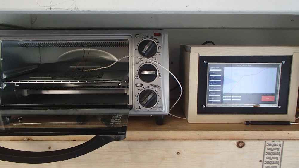
The reflow oven is really rough around the edges, and all around a poor excuse for programming and hardware design. I did uploaded the code to GitHub though. The design is really simple though. Like a said in an early post, I used the chipKit Max32 and a touchscreen I purchased previously for the AquaPic. I also had a protoboard shield for the Max32 that I soldered the thermocouple amplifier board and MOSFET that fires the relay to. I didn't do any modification to the actual oven. I simply set everything to max and plugged it into an outlet that is controlled by a relay and the controller. Below is a picture of the overall setup. I still need to snap some picture of the inside of the controller enclosure.
I had one hell of a time tuning the PID loop. I originally had the update for the PID loop set to 1 second but that ended up being too fast. I slow it down to 5 seconds and that seems to work a lot better. Temperature is a slow process. If I hadn't spent a bunch time researching and learning PID process control, I would have just simply used a "fast", 100-500 ms, proportional control scheme.
There are lots of little bugs and quirks with this oven. First, even though I spend a lot of time tuning the PID loop, its not the best at regulating temperature. My biggest issue is the overshoot at peak temp. Below is a picture of one of the reflow cycles. Its kind of hard to see, but the green line is the setpoint and the pink line is the actual temperature. The oven takes a little bit to build up heat so that why the preheat stage doesn't follow. It's obviously better if the preheat slope is set to 1.0 C/sec.

Secondly, the thermocouple amplifier doesn't isolate the thermocouple or something, and if the thermocouple tip is touching anything grounded, it pulls the entire +3.3V control rail to ground. At least to the best of my knowledge. Another issue is that occasionally when the computer is connected to the chipKit and the oven is running, the LCD screen goes all weird. Not sure why that happens but its not a concern since I never run this with a PC hooked up. Lastly, the oven goes to "Off" after the peak is reached instead of cooldown. Its not a big deal except the graph is only updated while the oven is running. I did make a few changes to the GUI that are not reflected in the above picture. The PID gain text box has been removed, and the graph's Y-axis is a little bit bigger so to show the overshoot at peak.
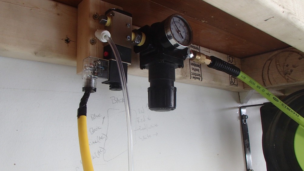
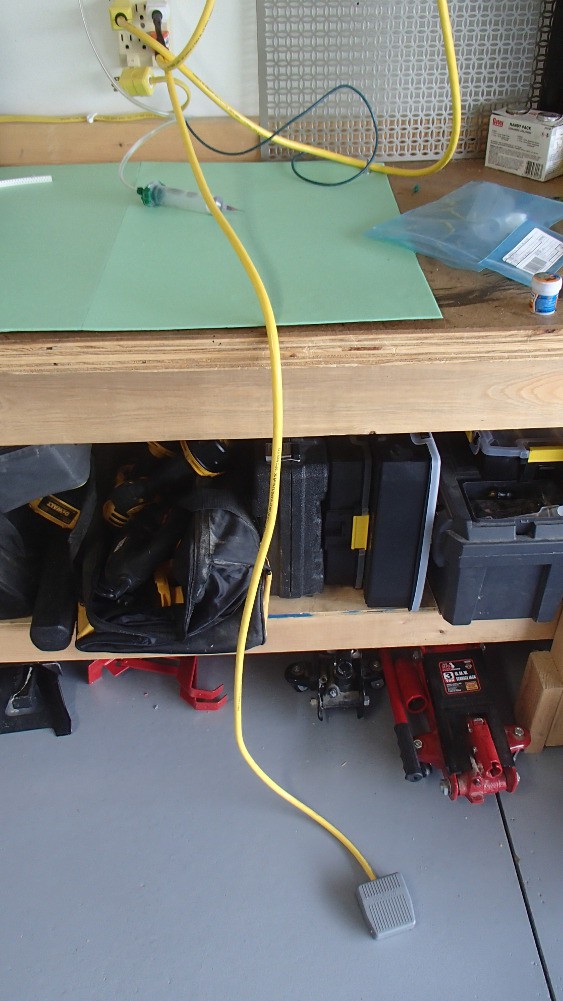
The solder paste dispenser actually turned out decent. Really the only issue I had was related to needle sizing. It takes a lot of pressure to push solder paste though some of the smaller needles. I still have some playing around to do before I figure out the perfect pressure/needle size combo to achieve the desired bead of solder. The dedicated pressure regulator I added made adjusting air pressure a breeze. Wiring everything up was straightforward. Its all 110Vac so I just run the hot through the foot pedal and back to the coil on the valve. The actual switch inside the foot pedal is a little wimpy and I'm guessing that is going to be the first point of failure. The cheap valve is working out though. I wasn't sure if it would shift fast enough for this application but it seems to be fine.
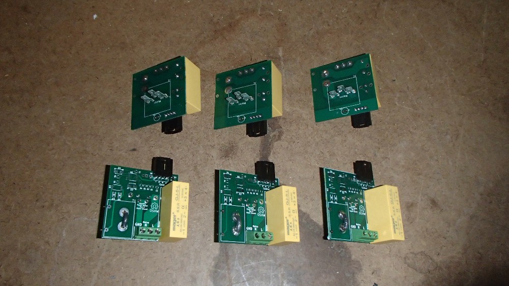
With a working solder paste dispenser and reflow oven, I was able to start assembling some boards. Well actually, just 6 copies of one board, the power outlet. For this first prototype I'm not including current sensing so there was only two smd components, a MOSFET and a resister. There actually should have been three smd parts but I forgot to order the flyback protection diodes. This isn't required for the outlets that will be controlled by a solid state relay, i.e. the 6 boards I already assembled. However, it will be required for the 2 outlets with mechanical relays. The rest of the parts on the outlet board were all through-hole and hand soldered. Below is how the outlet board and socket will go together. The outlet socket will be attached to the enclosure then the board's stabs will be inserted into the socket and left sort of free hanging.
Finished product so far:
During assembly of the outlet board I noticed an issue with it. I forgot to include a pull-down resister to the gate of the MOSFET. This won't be an issue when the outlet board is connected to a driven microcontroller pin. However, if the outlet board isn't connected to the control board or the control board isn't power up, the state of the MOSFET and therefore the relay will be unknown.
Discussions
Become a Hackaday.io Member
Create an account to leave a comment. Already have an account? Log In.