Paul Gould
-
New Arduino Zero (32bit) Compatible Controller Prototype
07/05/2020 at 17:08 • 0 comments -
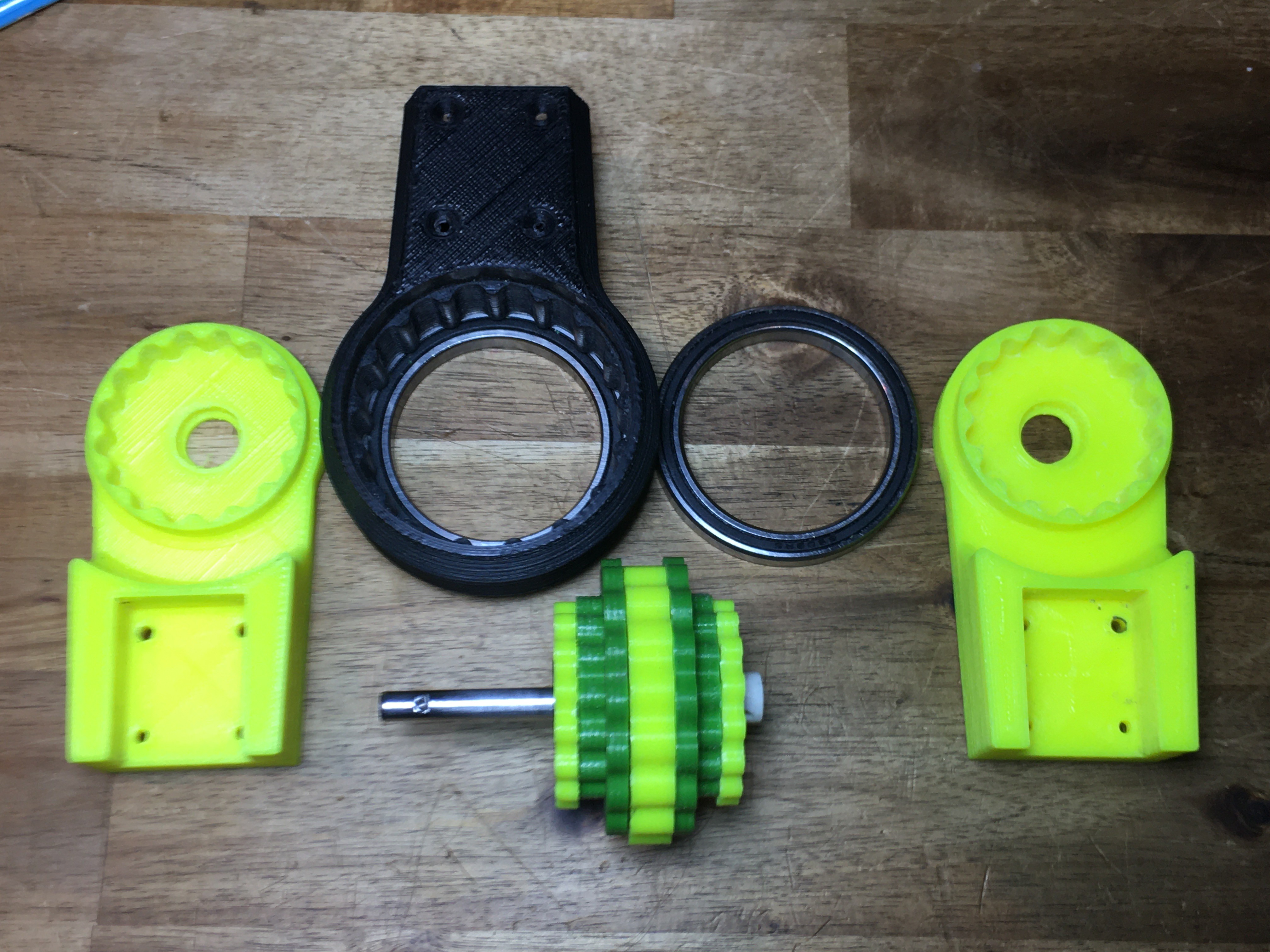
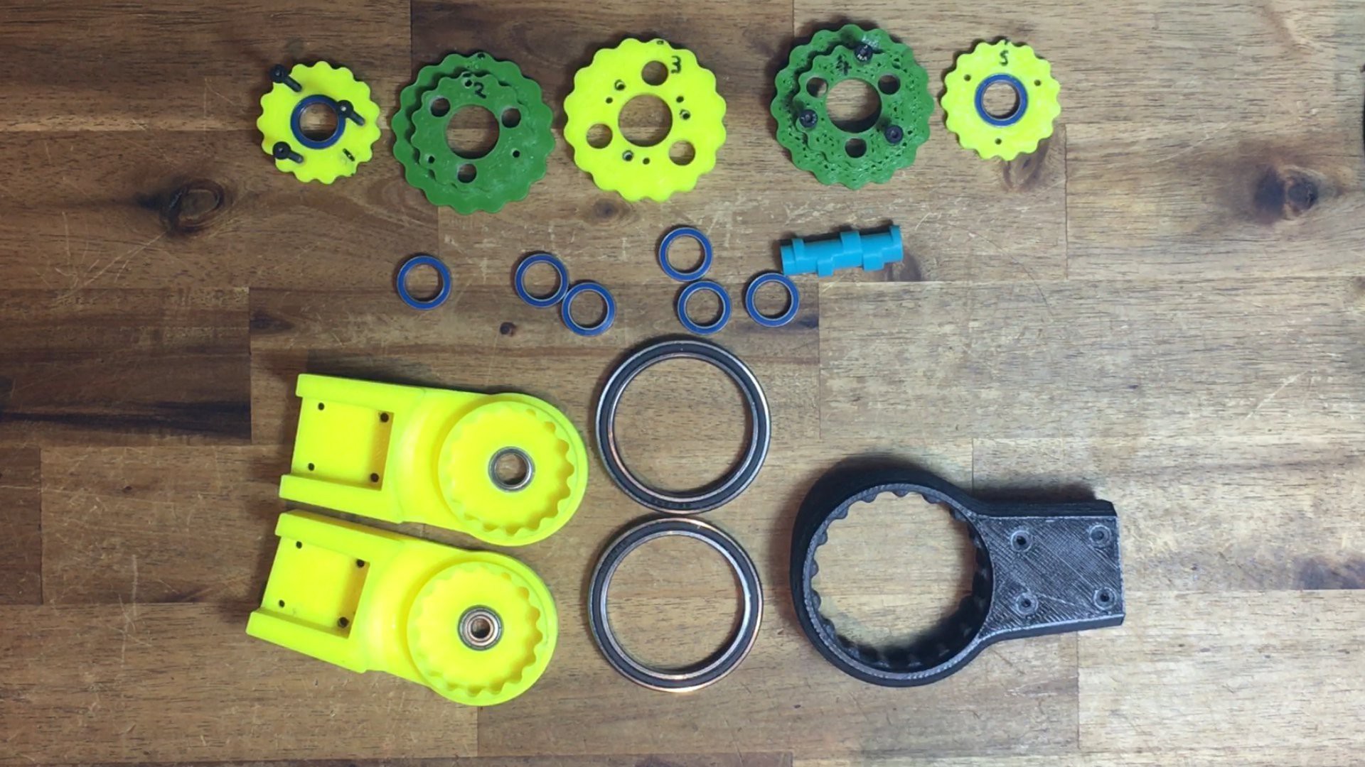
Triple Dual Stage Cycloidal Gearbox
05/31/2020 at 09:36 • 0 commentsMore development on Cycloidal Gearboxes
240:1 reduction ratio
![]()
![]()
-
Double Dual Stage Cycloidal Gearbox
04/05/2020 at 14:45 • 0 comments -
Initial Development - Magnetic Gearboxes
02/03/2020 at 15:09 • 0 commentsBefore I settled on Cycloidal gearboxs I did some other experiments
-
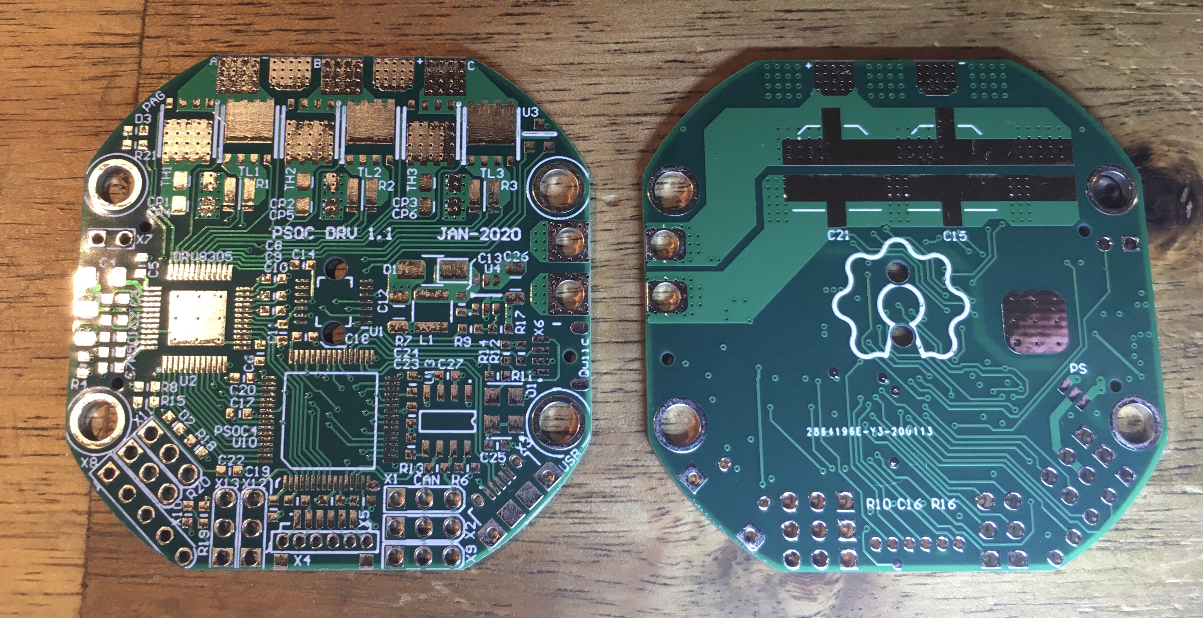
Making the Smaller PSOC4 Brushless Actuator Controller
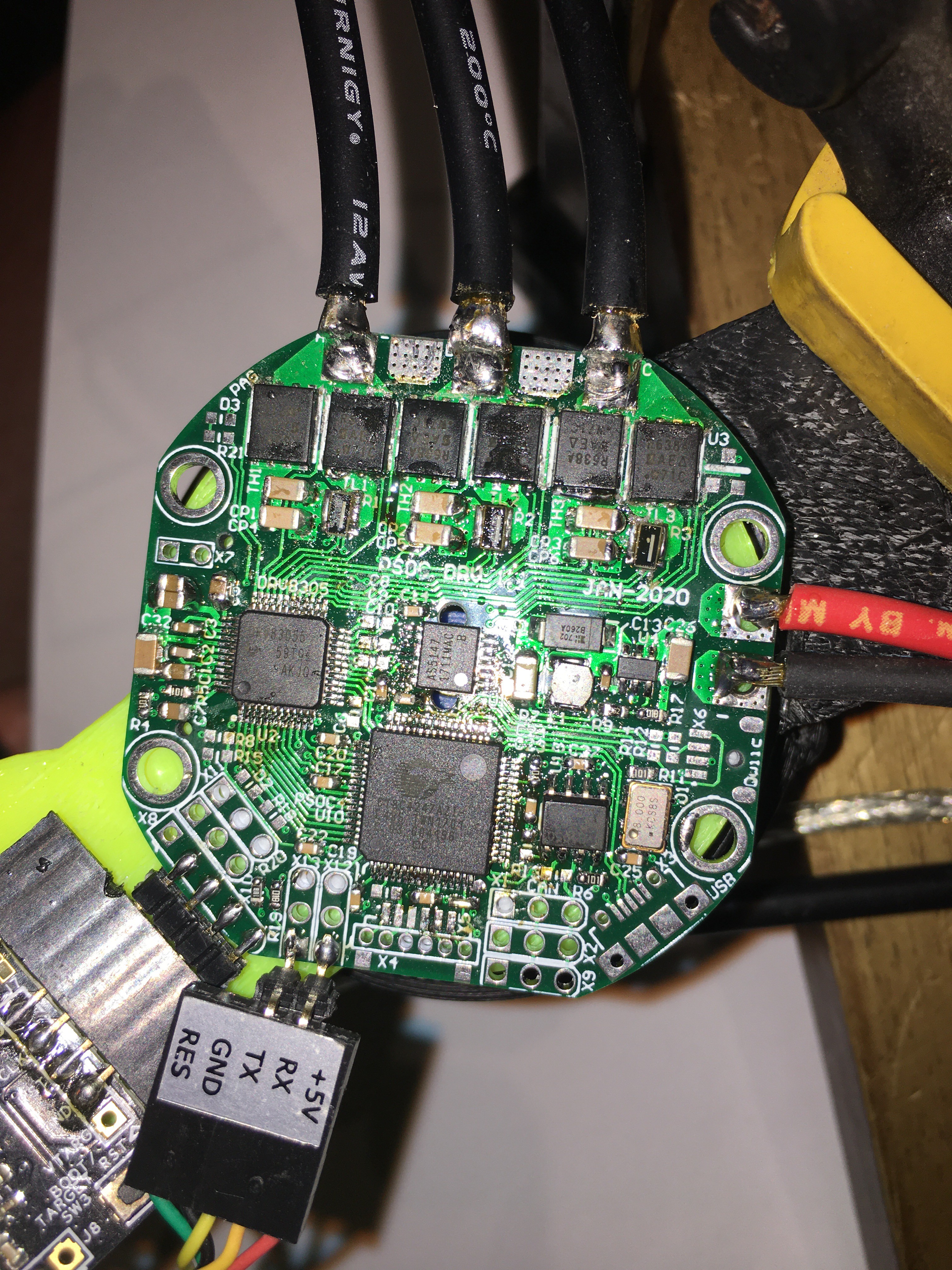
01/22/2020 at 16:50 • 0 commentsBoards got delivered from JLC PCB. Ordered on Monday night, arrived in Australia on Monday morning.
10x 4 layer boards + Shipping = AU$35.75
![]()
Internal Power planes were checked and all seamed fine. Next time I will order gold boards.
Via hole centering is slightly better than the last boards I had made at PCBWay.
Surface finish is not as good, but I think I ordered a better finish last time.
Silkscreen is clear and much better aligned.
I am happy with the boards.
I populated the board by hand using a soldering iron, solder and solder wick.
I will order a stencil next time or just get JLC to populate the PCB. I may still order a stencil for the remaining boards.
I took two nights to populate and 90% test the boards.
![]()
Motor is running from this board, so the follwoing are working
- PSOC4
- DRV8305 (SPI configuration, Internal Regs, PWM inputs FET Gate Control, Current Amps)
- Absolute Magnetic Encoder via SPI
- Crystal
- 5V SM Regulator
- UART
Next to test
- CAN, USB, Second UART
- I2C on Qwiic connector, for an OLED display
- SPI for External Absolute Encoder
- Analog Inputs, Temperature Sensors (Internal and External)
- LEDs, Voltage Monitor
- 2x Servo Outputs
-
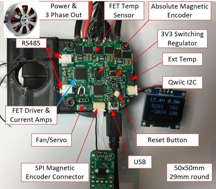
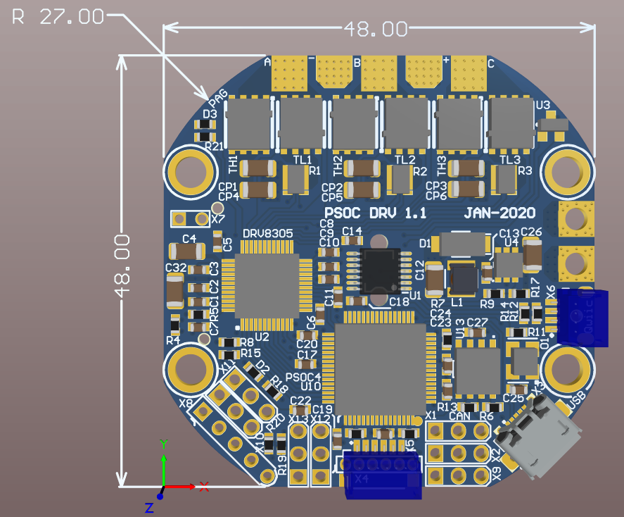
Smaller PSOC4 Brushless Actuator Controller
01/15/2020 at 14:31 • 4 commentsSmaller form factor with on-board magnetic encoder
1KW Peak 8S (34V @ 30A)
JLC just completed PCB manufacture (DHL shipping 4-5days)
PSOC4 SOC (CY8C4247AZI-L485)
Smart MOSFET Driver DRV8305 with three Current sensors
6x SIR638ADP-T1-RE3 40V 0.88 mOhms PowerPAK SO-8
3x 1mOhms with Kelvin Terminals
Centre Mounted AS5147 (or AS5047/48) Absolute Magnetic Encoder 14-Bit
5V @ 600mA Regulator
MOSFET Temperature Monitor
External Temperature Sensor Connector
Voltage Monitor
CAN 2.0B
USB FS
2x UART
I2C Qwiic (For OLED Display)
External SPI (single/Dual) Absolute Encoder Connector
Programmer Connector
2x Servo Outputs or 2x Analog Inputs
4 spare IO
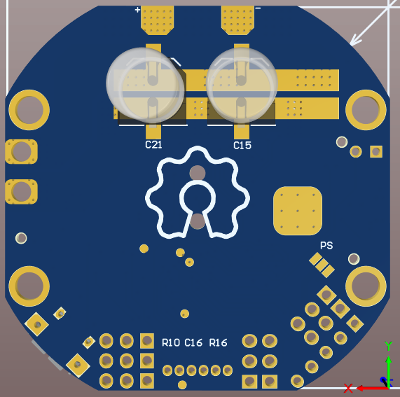
Back of Board
Strip of Ceramics or two Electros
New Logo
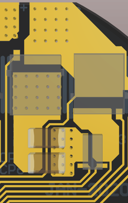
Tightly couple Half Bridge
-
Arduino Brushless FOC Controller - Development
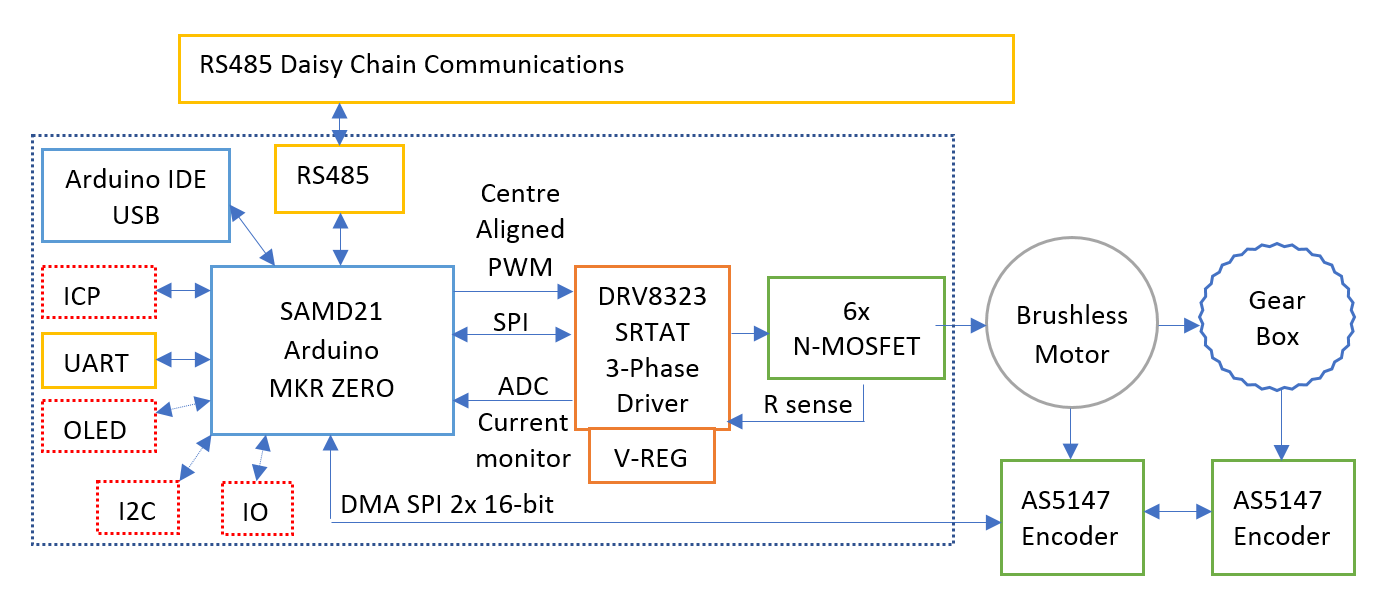
10/20/2018 at 08:08 • 4 commentsThe Cypress PSOC4 Controllers are not very common in the maker community. As I would like more makers to be able to use/modify/improve this Actuator, I am designing an Arduino version. It will be based around the MKR Zero with the SAM D21.
Earlier I got the Centered Aligned PWM working for controlling the MOSFETs for driving the Brushless motor. Next was the SPI for reading the Magnetic Absolute encoders for the motor and joint positions. The SPI on the SAMD21 only has a single buffer which is not time efficient for this application. It does have a DMA on the SPI which is much more complex but the most efficient for operation. The problem is that it is not a standard feature for the Arduino system.
I started with the following information.
https://forum.arduino.cc/index.php?topic=344029.0
Now the Adafruit Zero DMA library makes it too easy
https://github.com/adafruit/Adafruit_ZeroDMA
and can now be installed by the standard Arduino IDE --> Sketch --> Include Library --> Manage Libraries
It also support Interrupts "dma_callback" to tell when the transfer has completed.
-
Robot Control software (for initial testing)
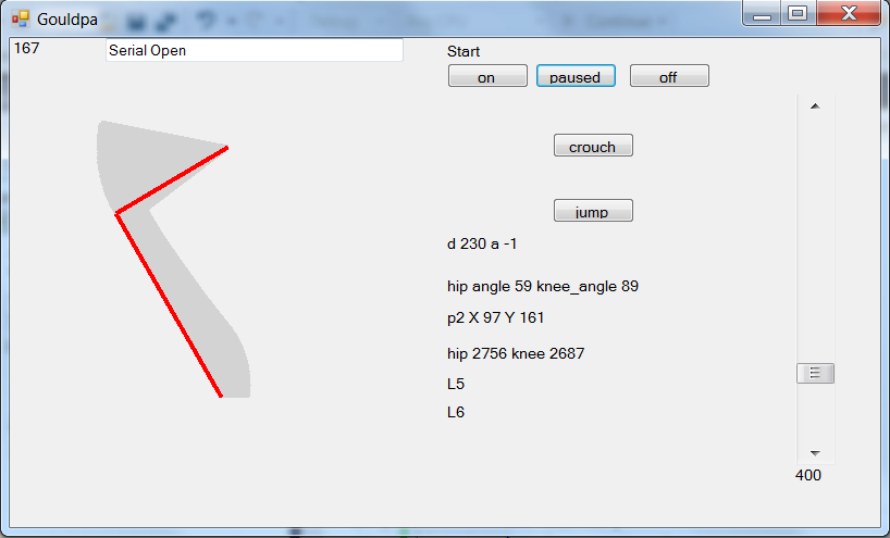
10/13/2018 at 16:09 • 4 commentsVisual Studio and C# in .Net was used to write a simple test program. An X,Y foot position is generated, converted to hip and knee angles using Inverse Kinematics and sent to the serial to CAN converter (spare PSOC actuator controller). These packets are addressed to the two robot actuators to move to the required position. A second mode just returns Joint positions.
-
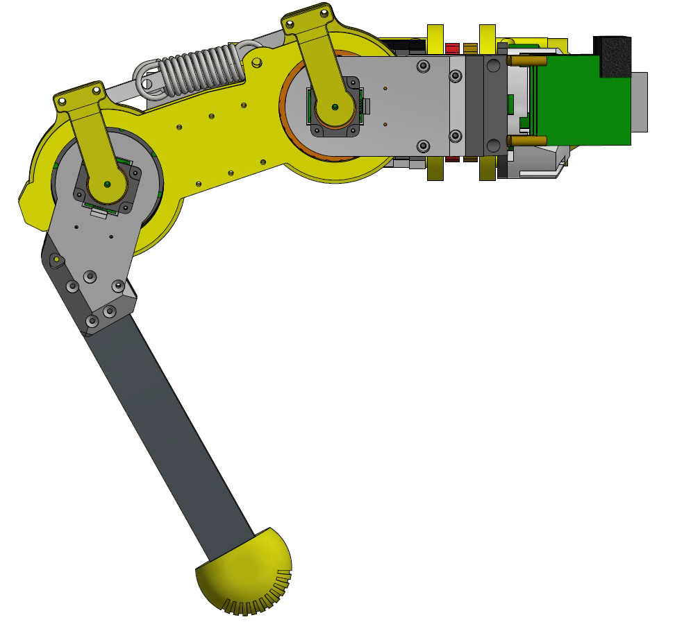
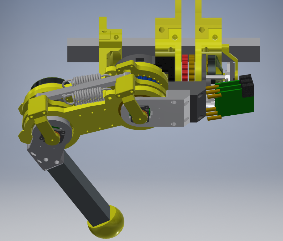
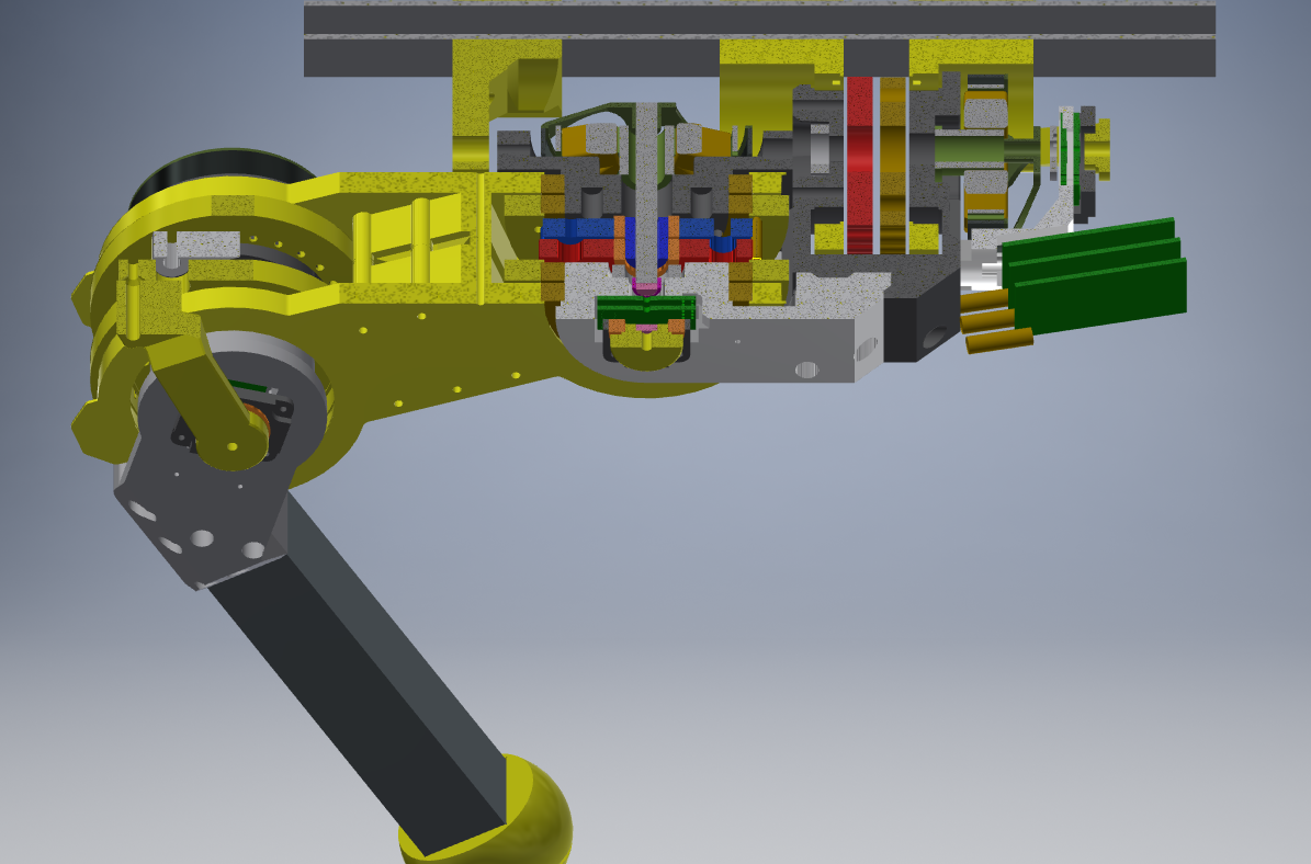
Series Elastic Actuator - CAD
10/13/2018 at 16:02 • 4 commentsI have modified the base robot actuator to make it into a full robot leg for a quadruped. It has a parallel linkage with springs and 2 robot Actuators. This means that the spring direction changes from rotation to almost vertically linear when the leg is in the standard walking positions. Different strength springs can be swapped for testing, with the aim to store energy at the end of a jump cycle and use it for the next jump. It will also be used for efficient walking/running.
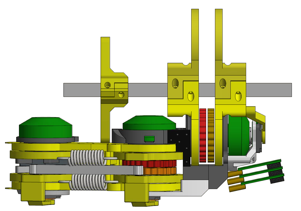
Everything rotates around the same joint, for the centre joint, described from top to bottom of the drawing.
- 6mm shaft running most of the way though
- Motor bell and flux ring
- Stator housing with 2 motor bearings
- Top outer housing
- Top Thigh plate with 6809 bearing
- Top Series elastic output plate (also actuator output shaft) with 6809 bearing
- Eccentric Cam with 2 lobes with 2 bearings each and 2 cycloidal gear
- Bottom Series elastic output plate (also actuator output shaft) with 6809 bearing
- Bottom Thigh plate with 6809 bearing
- Bottom shaft mount with bearing
- Motor angle Magnet holder
- Motor magnet (diametric)
- Bottom outer housing
- Motor position PCB
- Silicon steel flux cancellation plate (0.5mm thick)
- Joint position PCB
- Joint bearing holder (old protects the PCB)
- Joint magnet (diametric)
- Joint angle plate with bearing
3D Printed Robot Actuator
A high speed and high torque robotic actuator using low-cost brushless motors, custom controller, 3D printed parts and bearings.