Close
0%
0%

High Efficiency MPPT Solar Charger

A 75 watt MPPT Solar Charger with tons of features. Efficiency > 97%, USB interface, data logging, 2 USB charging ports and much more...

Similar projects worth following
After 3 years of development, this open source project is nearing completion. From its modest beginnings it has evolved into a rather sophisticated device with a USB interface, powerful USB charging ports, a 20x4 character LCD, a rotary encoder with push button, precision measurement of everything from voltages and currents to temperatures. There are 4 PWM power outputs, 4MB of storage for a year's worth of data logging with real time clock and calendar. It connects to a desktop app via USB where users can monitor and adjust every aspect.
But what makes this charger truely special is its extremely high efficiency of around 97% over a very wide power range from 1 to 75 watts. And there's more: When there is no sun, this charger won' t drain your battery. It will enter a very low power state where most sub-circuits are powered off while still logging data.
It works with any type of battery with a nominal voltage of 6 to 13 volts.

Versatile stand-alone or as a Module

While this project started as a stand-alone solar charger, is is nowadays often used as a module in larger projects. The prime example of this is MeshPoint, a WiFi hotspot for disaster and outdoor areas. That project is all about WiFi and 4G mobile networks, not about power harvesting. Using this solar charger as a module, Valent and his team can focus on WiFi connectivity without getting overly distracted with power management.

Don't re-invent the Wheel

Whatever your project, if there's no wall outlet nearby you will sooner or later have to worry about power. Developing a quality solar charger is a major project in its own right as I have found out over the course of the last few years. Chances are high that your project's specific requirements can be met by this charger. It works with many types of batteries over a wide power range. Very often, it is only a matter of configuration to make it fit your needs. So don't re-inventing the wheel. Use this solar charger as a module in your project and focus on what you really want to archieve.

For more involved projects like MeshPoint mentioned above, you may decide to customize the hardware by laying out your own PCB so that it pysically fits and maybe even strips some features that you don't need. Even so, the work involved is only a small fraction compared to starting from scratch.

If your can live with the hardware as it is, your life is even simpler. Just decide if you need the user interface or not and start configuring your charger. The various interfaces from SPI over I2C to USB make it easy for your application to communicate with this charger. 

Standalone Use

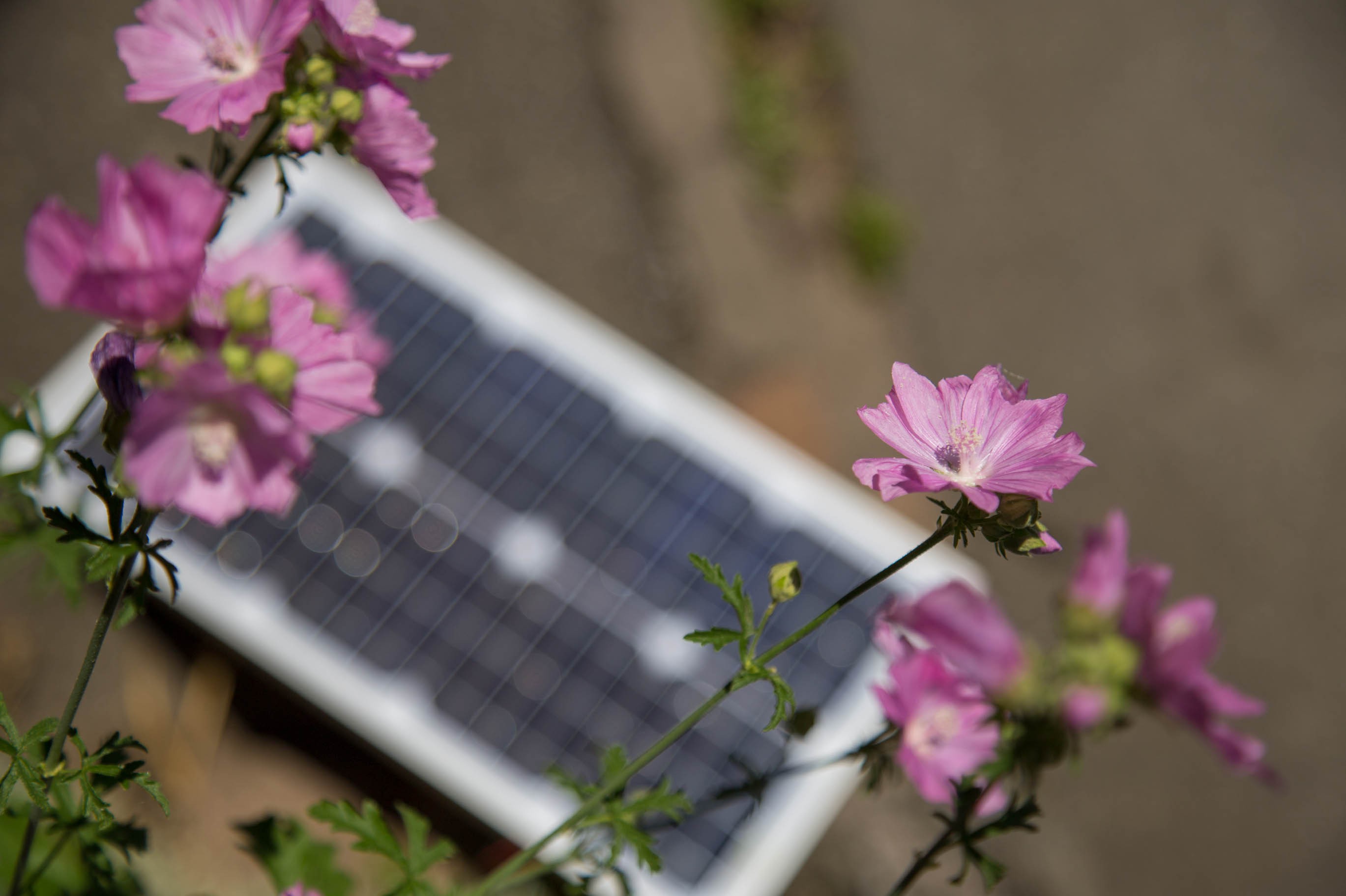
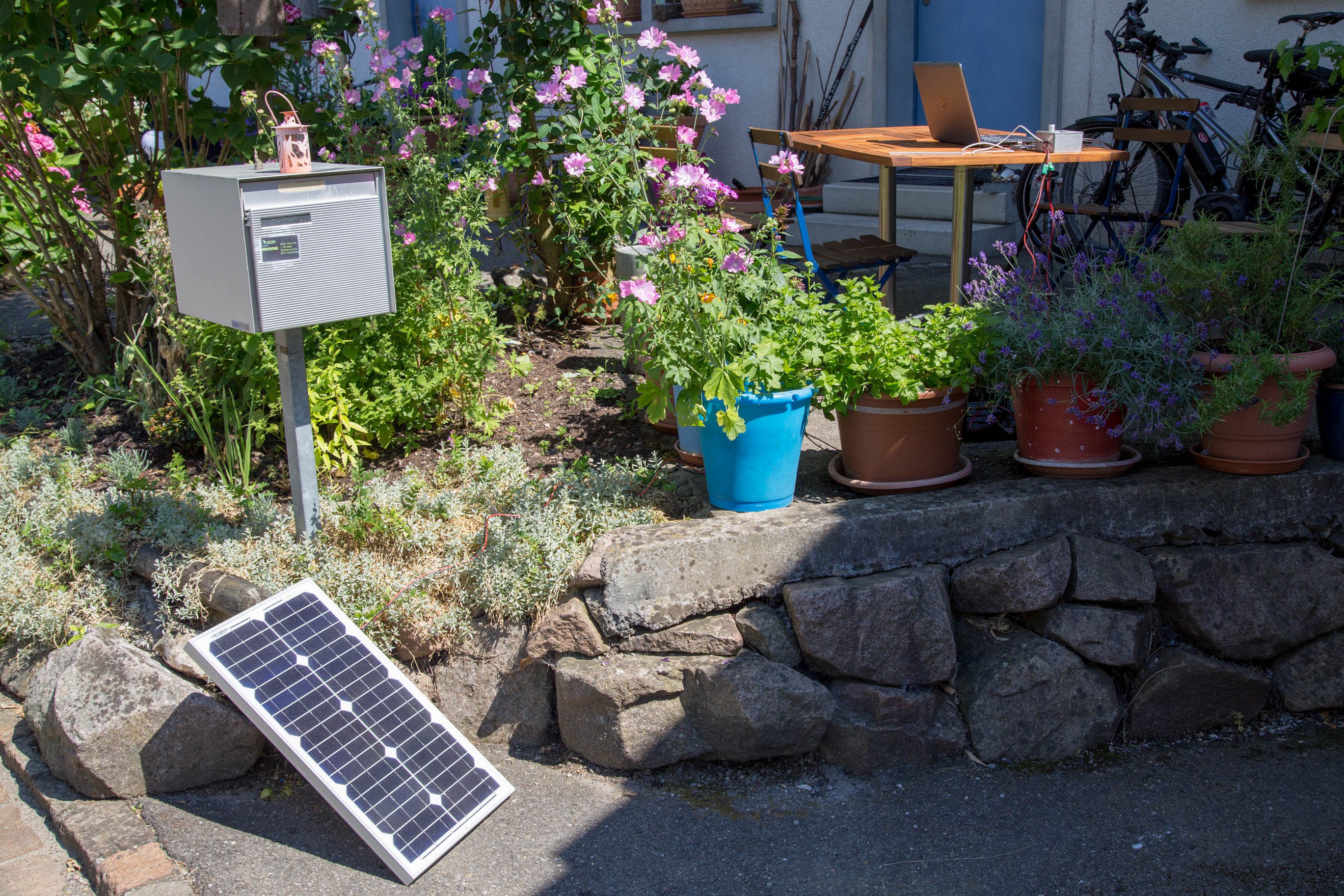
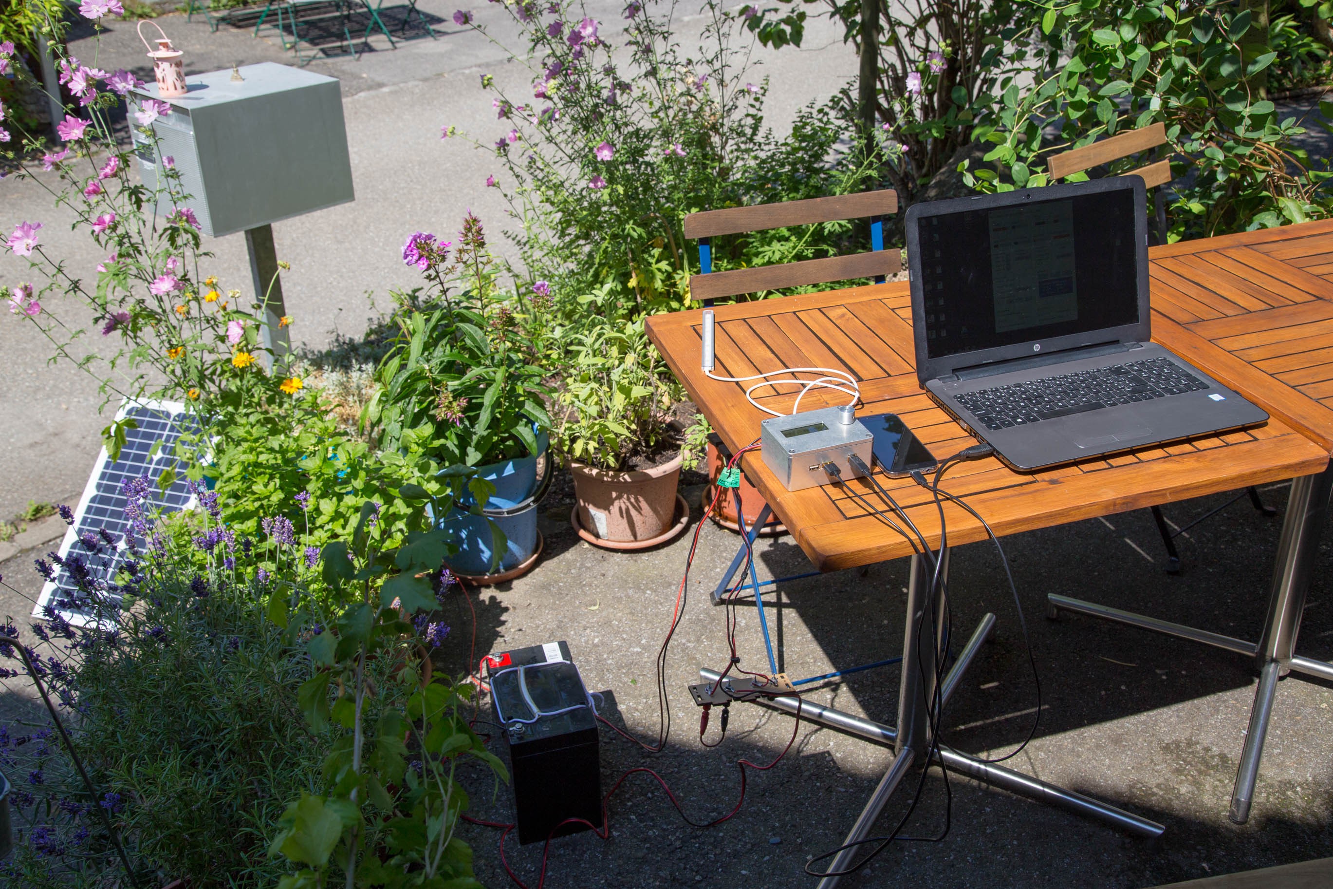
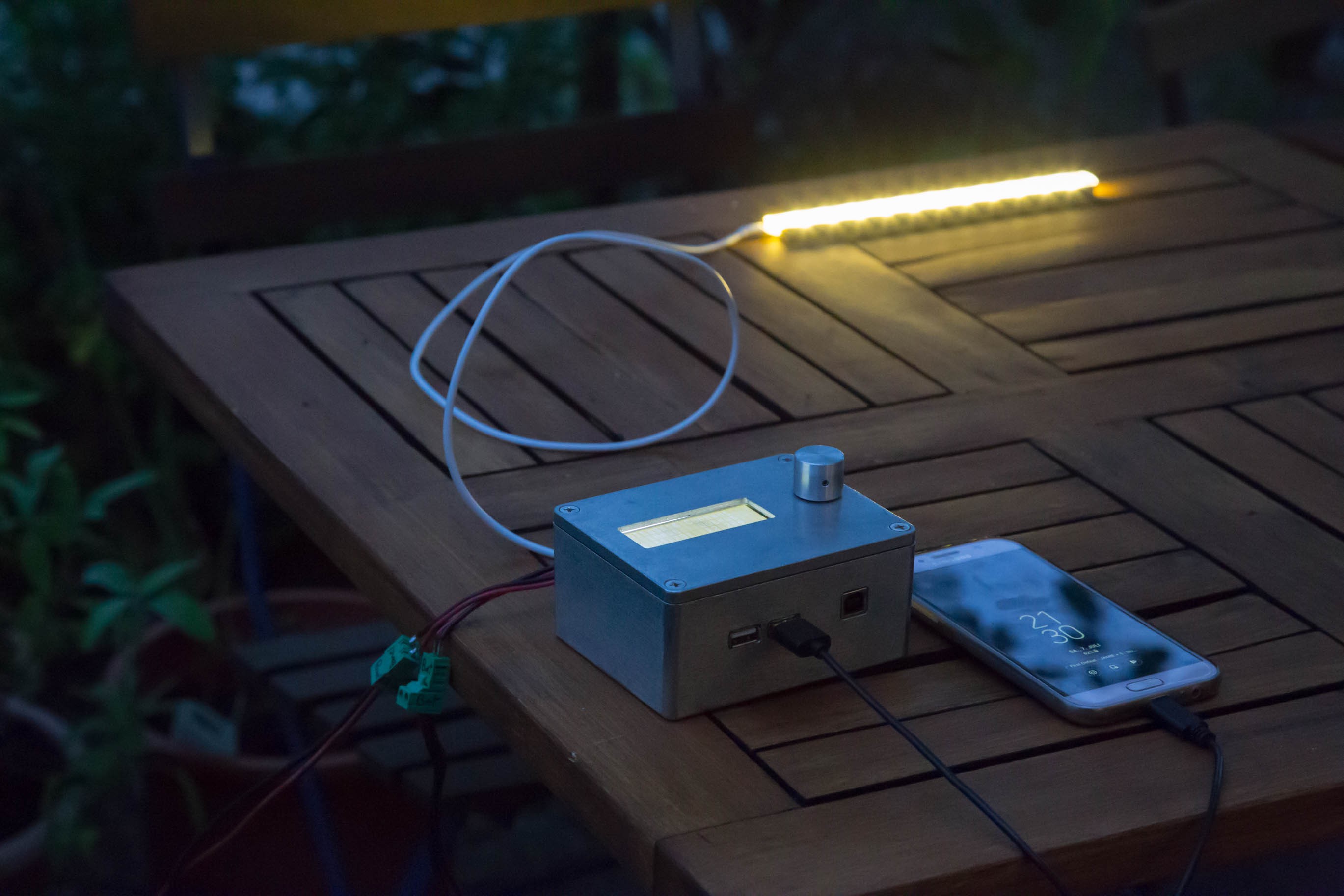
There are many situations where one needs (or would simply like to have) power but there is no wall outlet anywhere near. Be it a camper van, a boat, or an off-grid hut. Its nice to have some power for electric lighting, charging cell phones and more. And the availability of affordable solar panels makes solar often the energy source of choice in such situations. 

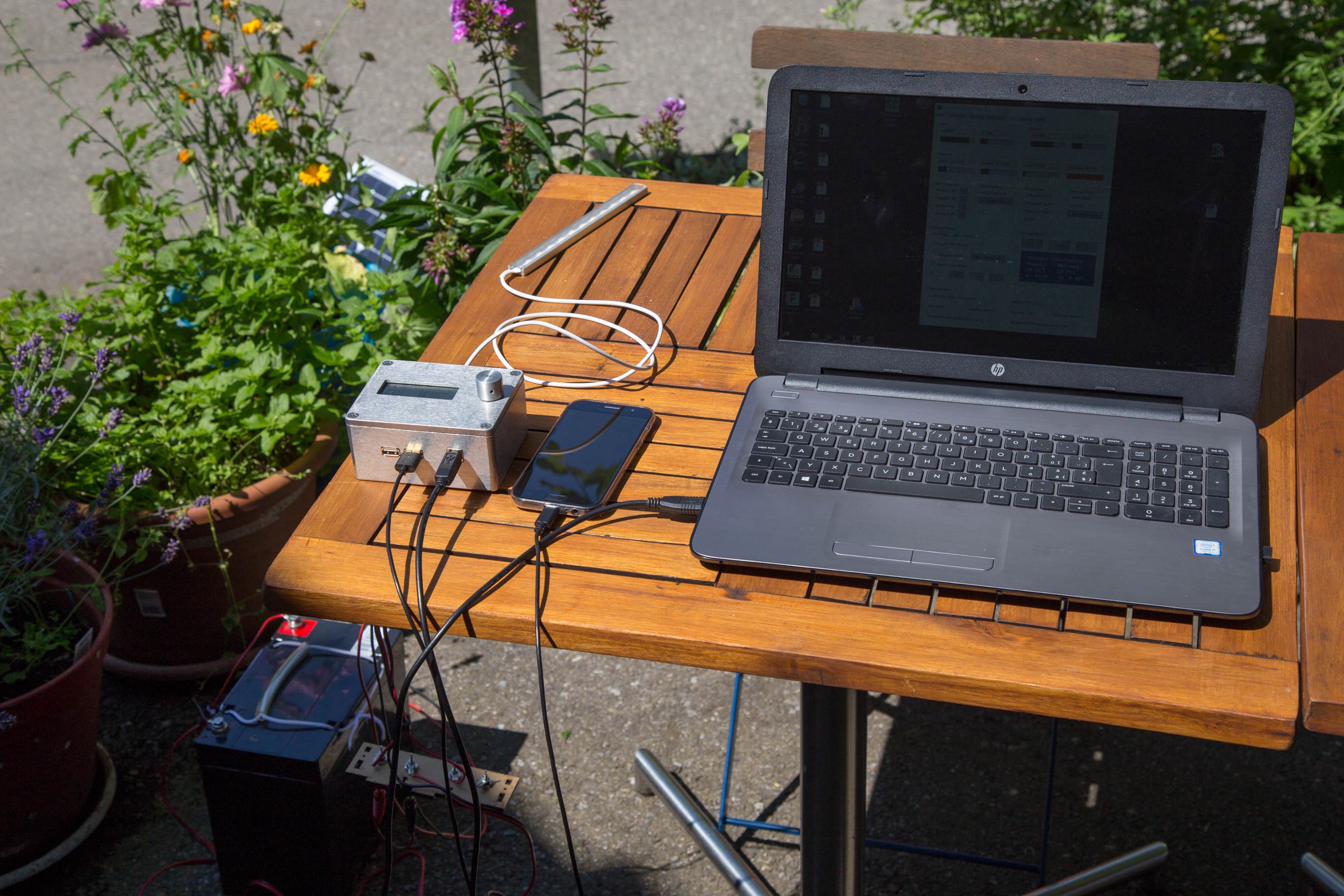
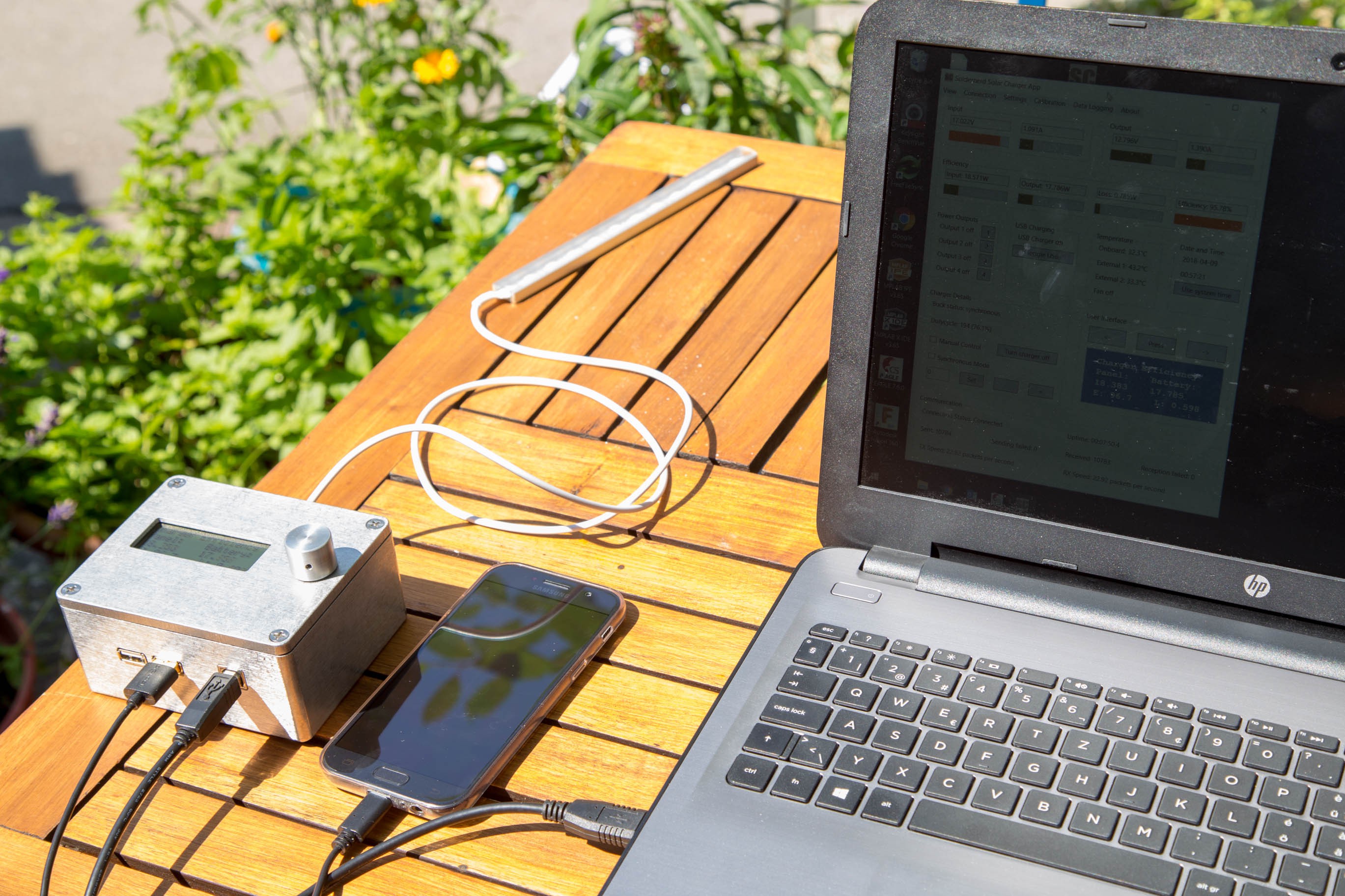
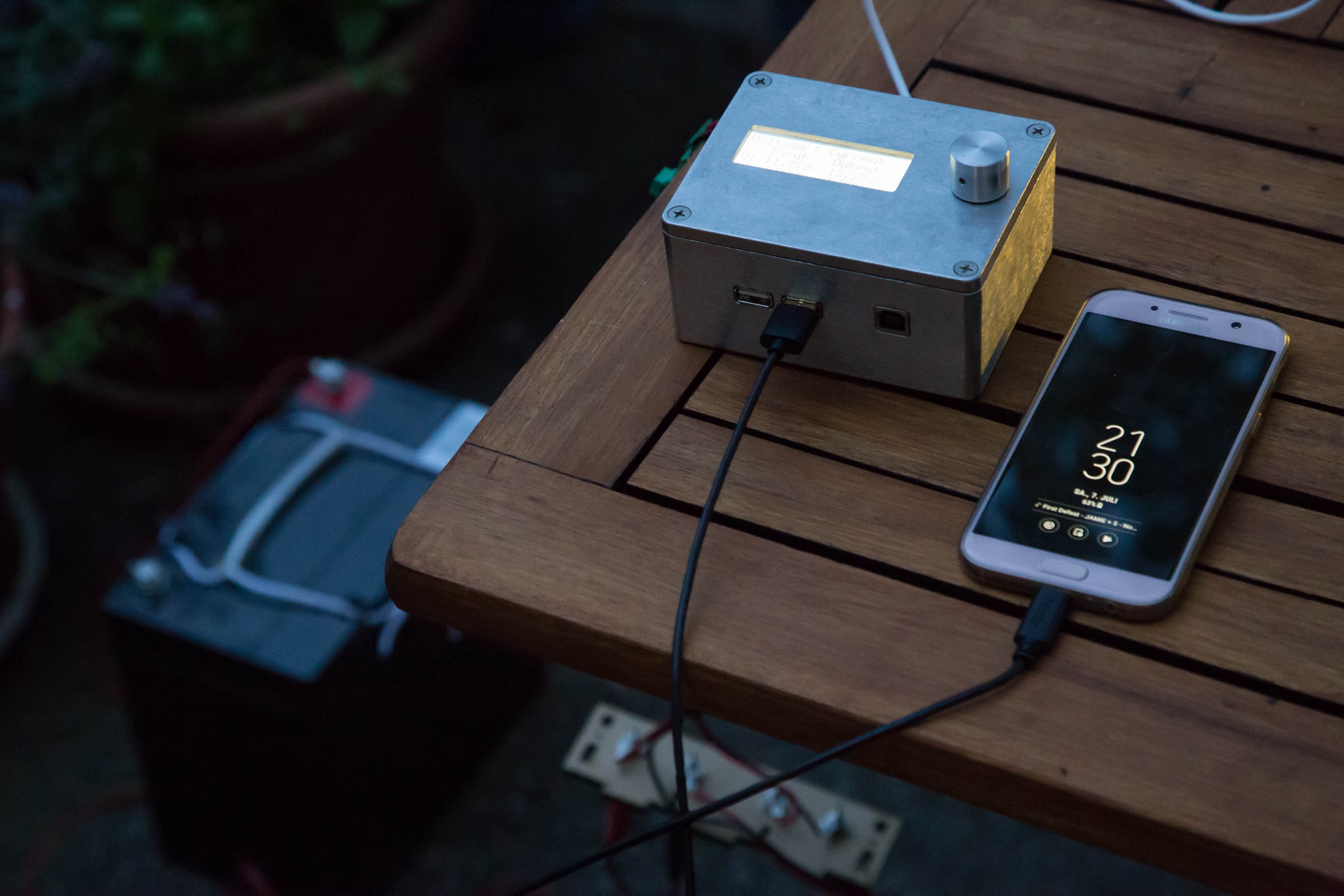
Yes, you could just buy one of the countless solar chargers out there. But if you are like me, you want a bit more than a black plastic box. I want to see what's going on, I want to be able to control and configure it, I want to be able to adapt it to my specific needs. I want to be able to connect my laptop computer and see what it did while I was away. If you are so inclined, this charger is for you.

Beyond Energy Harvesting

There are also ways how this charger can support your project beyond providing energy. For example, you can access the real-time clock and calendar via any of the interfaces. You may also store data on its EEPROM or its 4MB flash chip. 

If your project is about logging environmental data, you may even rely entirely on this project. The two analog inputs originally intended for temperature measurement can also be used for other purposes. If you need a bit more than that, you can connect an external ADC directly to the I2C or SPI interface and let the solar charger do all the work. All you will need to do is to customize the firmware so that it takes care of your extra hardware.

Beyond Solar

There is even a project harvesting wind energy that decided to use this solar charger as a starting point. While a wind turbine is certainly different from a solar panel, there are many similarities. It's all about extracting as much energy as possible and converting it in an efficient way. Starting with this open source design saved countless hours in both software and hardware development.

Features & Details

High Efficiency DC-DC Buck Converter

At the core of this project is a highly efficient DC-DC switcher rated at 75 watts and entirely controlled by software. It operates at 187.5kHz and can operate both in synchronous or asynchronous mode. The latter is more efficient at light loads. Together with the careful layout and thoughtfully chosen components this allows...

Read more »

SolarCharger_RevF_Specs.pdf

Datasheet with specifications and input/output requirements

Adobe Portable Document Format - 131.34 kB - 10/21/2018 at 21:53

Preview
Download

UserInterface_RevC_Schematic.pdf

Complete schematic for the user interface board, revision C, as a PDF.

Adobe Portable Document Format - 58.66 kB - 07/23/2018 at 21:00

Preview
Download

SolarCharger_RevF_Schematic.pdf

Complete schematic for the main solar charger board, revision F, as a PDF.

Adobe Portable Document Format - 135.27 kB - 07/23/2018 at 20:59

Preview
Download

SolarCharger_RevF_BOM.xlsx

Bill of materials for the latest revision of the solar charger

sheet - 21.10 kB - 07/10/2018 at 20:58

Download

SolarCharger_RevF_Gerbers.zip

Gerber files for the latest revision of the solar charger. The gerbers are exactly the ones that I used to order my boards from dirtypcbs.com

x-zip-compressed - 160.57 kB - 07/10/2018 at 20:56

Download

View all 7 files

  • Contest entry video online

    Lukas Fässler10/21/2018 at 20:42 0 comments

    Better late then never: My official contest entry video is finally on youtube. This is a requirement for participating in the finals and the deadline is tomorrow morning. But now it's online on time - Please check it out and I hope you like it.

    I've also double and triple checked that this project meets all the other requirements. So for the moment I can't do more than to keep my fingers crossed and hope for the best. Wish me good luck and thanks for your support.

  • Solar Charger Making Of - New Videos Online

    Lukas Fässler10/13/2018 at 22:11 0 comments

    A bit more than a week ago I talked about separating the API functionality from the USB code as well as integrating the new FAT16 implementation into the SolarCharger firmware. That is done and committed to github. 

    But there is more: I finally cut several hours of video that I took months ago. The result is two new videos showing how I'm building a SolarCharger and a user interface, respectively. They are relatively short, just a few minutes each, with lots of time lapse condensing hours of hard labour into hopefully joyful minutes on youtube.

    Here's the first of the two. Watch a SolarCharger being built. No talk, just some comments in the subtitles. 

    The second one is somewhat more educational. I walk and talk you through the entire build of a user interface from applying the solder paste over placing the SMD components and reflow soldering to adding the through-hole components.

  • Done with the Bootloader for now - Continuing with Charger Software

    Lukas Fässler10/03/2018 at 21:16 0 comments

    There's not much to show in terms of pictures but the last few weeks have seen intense work on the bootloader software. Most of the FAT16 implementation has been re-written, API functionality added, tested and debugged. It is now possible to write files to the flash drive with a minimum of write operations. This is possible by cleverly buffering data in RAM before performing an actual write on the flash. This means, each page only needs to be written once, even when sending data in small chunks. So the flash (which has a limited number of write operations) will not wear out even if the firmware is updated very frequently.

    With that work behind me, I have once again turned to the acual SolarCharger firmware. A number of code files are shared between the bootloader and the charger software. That includes the FAT16 implementation mentioned above but also all the USB code and hardware drivers. The first step was to integrate them and make everything compile again. That's done. So the charger immediately profits from the work I did on the bootloader.

    What remains to be done is to separate the API functionality from the USB code. The charger has its own API which previously has only been available via USB. Now I'm putting this into a separate module so that it can be accessed via any of the interfaces. Exactly the same thing I did for the bootloader a few weeks ago. Once that's done, it's automatically accessible via SPI as well - That code is shared with the bootloader and already in place. I expect this to be all up and running by the end of the week.

    After this rather technical step I will resume to work on more visible features again. I'm very much looking forward to it. There are several things to be done:

    • PWM outputs: Since Rev E the hardware is capable of PWM control on the power outputs but the software to do that still needs to be written.
    • Explore further MPPT algorithms. I'm currently reading some papers on the topic but I'm looking for more material. If you know any good source of information, please let me know.
    • Make use of the 12-bit ADC for temperature measurements. As above, the hardwar can now do it but the software only uses 10 bits at the moment.
    • User interface: Some of the screens were really only intended for debugging. It's time to throw those out.
    • Low-power features: More needs to be done to reduce standby current consumption. There are many hardware features not fully utilized yet in that respect. 
    • Debug and finalize data logging


    So you see, I'm not running out of work. I have one of those chargers set up here in my office with a panel just outside the window and it's harvesting power every day. But there are always things that can and should be improved, particularly in software. I'm on it.

  • First videos on youtube

    Lukas Fässler09/10/2018 at 21:37 0 comments

    I finally managed to cut two short videos of the bootloader in action and to upload them to youtube. Here they are. I hope you enjoy them and let me know if you have suggestions - I'm relatively new to video.

  • Charger can be programmed via SPI. Finally.

    Lukas Fässler09/09/2018 at 00:06 0 comments

    After countless hours of writing and debuggin (mainly debugging ;-)) bootloader software I can finally program the device via its external SPI interface. The bootloader was originally a pure USB MSD (MassStorageDevice) bootloader. To make it more universal, particularly in an embedded context, the idea was to allow file access via an API which can then be made available via SPI, I2C as well as USB HID (HumanInterfaceDevice). 

    An important milestone on this journey has now been reached. One can now create, delete, rename and modify files via the API. Once a firmware file has been created in this manner, the original bootloader can do its job and program the new firmware.

    Why did it take so long? Hard to tell, really. With hindsight, there was nothing too difficult about it. But as so often with embedded software, sometimes it takes days to get a seemingly simple piece of code to do what it should. 

    At an early stage, I reviewed and re-wrote a pice of code so many times trying to find out what's going wrong. I read the PIC data sheet back and forth thinking I must have overlooked something. In the end it turned out to be a bad soldering joint...

    I've also archieved a massive performance increase in terms of time it takes to write the firmware. It's now impressively fast and only takes seconds - Something I very much appreciate during testing when I re-program the charger many times a day.

    That said, some more work needs to be done to further improve the FAT16 implementation. It's still quite inefficient when writing files. I'll need to change that so the flash won't wear out over time. The flash chip I use has a guaranteed 100k write cycles which sounds like a lot but is quite easy to reach if your code is not careful.

    It's 2:05 a.m. here so no photos for today but I hope to post a video of the bootloader in action tomorrow.

  • Debugging external I2C and SPI interface

    Lukas Fässler08/15/2018 at 22:03 0 comments

    I've returned from two weeks of summer holidays on Sunday and have immediately resumed working on this project. Before I went on vacation I did quite some coding on the bootloader in order to get it ready to communicate to the outside world via SPI and I2C. But during all that time, I had no means of testing the software. All I did was to make sure my changes didn't break any existing functionality.

    In order to test and debug those interfaces, I first needed another device using them. A RaspberryPi was an obvious candidate. I already had one but I haven't used it for a year or two so I first set it up with the latest version of Raspian and searched for a suitable library to handle the low-level details of the RaspberriPy's SPI and I2C ports.

    After consulting google I decided to use the library by Mike McCauley (http://www.airspayce.com/mikem/bcm2835/index.html) and the corresponding Python bindings (https://github.com/mubeta06/py-libbcm2835). So I was first busy downloading, compiling and installing software packages and to get the RaspberryPi up and running in general. 

    When I was half my age, I used to work on Debian and that Linux experience proved valuable in the process. But my knowledge on the subject has rusted since and it took me a while. Finally, I soldered some wires with 100mil connectors to both the Raspy and the charger so they hopefully soon communicate via SPI. This setup allows me to quickly and easily connect and disconnect the two boards and also make it easy to connect a scope in between.

    The scope is also set up and triggers on any SPI communication. The python library also seems to work just fine, at least I can configure and access any of the GPIO pins. So I can start now with the real work ;-)

  • Hackaday Prize Finals

    Lukas Fässler07/26/2018 at 20:55 0 comments

    I'm delighted to tell you that this project has been selected to run in the Hackaday Prize Finals on October 22nd. The last week I've been working on this project day and night. And I mean that quite literally: I was still soldering some more boards at 1:30 a.m. when the email with the happy news arrived.

    There are three things I'm currently working on: 

    1. Getting some more chargers out into the field in order to get some feedback from real-world use. That's why I'm busy soldering. One charger is now constantly deployed at my home and another one is on its way to Norway. At least two more will go to Croatia where Valent is working with some schools that run them for educational purposes and experiment with different algorithms.
    2. Finalizing the bootloader. I've spent many hours cleaning up the code and extending the API. The goal is to have a universal USB / SPI / I2C bootloader. It turned out to be a lot of work but I'm getting there.
    3. Posting some videos: I'm not really up to speed when it comes to cutting videos I had to notice. I've recorded quite a few videos from outdoor testing, the bootloader in action as well as soldering. But I still have to cut and edit them somehow before they go on youtube.

    I'll be on vacation for the next 2 weeks but after having been selected for the finals I'm more motivated than ever to finalize this project.

  • USB MSD Bootloader Ready

    Lukas Fässler07/09/2018 at 22:50 0 comments

    This project has just reached another important milestone: The USB bootloader is up and running. This part of the project will enable the non-technical end user to easily and reliably update the firmware in the field. 

    Unlike a USB HID (Human Interface Device) bootloader that requires some application to run on the host computer, this USB MSD (Mass Storage Device) bootloader requires absolutely nothing in terms of host software. It's entirely independent of the OS used. Windows, Linux, Mac, it all doesn't matter. As long as they can deal with a USB drive, they're good to go. Just copy the new software (in the form of an .hex file) to the Solar Charger drive and follow the instructions on the display. 

    It might even be that this bootloader is the world's first of its kind for the PIC18 platform. To be sure, this kind of bootloader has been around for years for more powerful 32-bit microcontrollers like ARM Cortex and the like. But in my online research I have been unable to find any other such project for the PIC18 family (or any other 8-bit microcontroller). So I had no choice than to write my own. If you know of any other implementation, please let me know.

    Once the file has been found and the user has pressed the button, the file is checked. If all those checks pass, we can be confident that we have a valid hex file. Of course, it doesn't tell us anything about the quality of that code, that's an other issue. But technically we should be fine.

    Once the checks have passed, the user is once again requested to press the push button to confirm that this file should be programmed onto the chip. While it's programming, it keeps displaying the current hex file entry it is processing to give the user an idea of the progress. It also keeps track of the number of flash pages it has written. One page corresponds to 1024 bytes on this architecture.

    Once all the new code is flashed onto the chip, a message is displayed and the user is asked to once again press a key to re-boot the device into normal operating mode.

    There are two different ways to enter bootloader mode. One is to press the push button at power-up. The other one consists in writing the value 0x94 (an arbitrarily chosen value) to the EEPROM address 0x100. In this case, the device will start up in bootloader mode no matter the state of the push button. The bootloader then overwrites this value (to 0x00) in order to start up normally next time.

    After the reboot, you should be greeted by the startup screen of the solar charger firmware as shown above.

  • Outdoor Testing

    Lukas Fässler07/07/2018 at 22:49 0 comments

    As much as I enjoy C programming, today the weather was just too nice to lock myself inside and stare at a computer screen. So I changed my schedule and did some real-life outdoor testing. 

    So I moved my 35 watt solar panel outside, grabed one of the Rev F solar chargers, connected a battery, my laptop and some more gear. 

    This is an ongoing project but it has been going on for almost 3 years so that the charger is mature enough to be deployed. Some software features are still missing and others are still a bit rough around the edges but it can easily be used as is.

    As a hobbyist, I do most of my development and testing late at night when there tends to be little sun so this represented a rare opportunity for me to do some testing with a real solar panel as opposed to a lab supply.

    As mentioned above, I only used a 35 watt panel which happens to be the only panel I have. So this test was not so much about pushing the charger to its limits but rather how usable it is at this stage of development and about how it performs in a more real-world setting.

    The test was rather unspectacular but successful for that very reason. I set it up and let it do its thing. And it just worked. It never crashed or performed weirdly. It just harvested energy all day long. Typically around 20 watts which was what the panel was able to provide.

    The solar charger app which I ran on my laptop also performed as it should. It worked reliably monitoring and controlling the charger without ever crashing. USB connection was never an issue. I plugged it in, started the app and it just worked.

    The 45Ah (I think) battery was relatively empty when I started so the battery was charged at full current without overcharging ever being an issue. Besides that, I used some of the energy to charge my cell phone.

    During most of the day, the charger sat in the sun while performing without getting overly hot. The on-board temperature stabilized around 45 degrees centigrade which can mainly be attributed to the sun, rather than losses in the charger.

    Later, after the sun had long set, I used a stip of warm white LEDs to provide some light. Rarely has embedded engineering been such a pleasent task.

  • Working on the USB Bootloader

    Lukas Fässler07/05/2018 at 21:59 0 comments

    It's programming time once again. More specifically, I'm working on the USB bootloader. The bootloader is extremely user-friendly: When connected to a computer via USB, it behaves just like a memory stick or USB drive. You then just copy the new firmware hex file to that drive and confirm that you want to use it. 

    As you may have guessed from the photo above, the bootloader looks for a file named FIRMWARE.HEX. Once such a file is found, it will display its size and ask the user if this file should be used.

    Once the button is pressed, the content of the file is checked. Is it a valid hex file? How many entries are in that file? Do the memory locations correspond to what we expect? Are all the check sums ok? There are a lot of checks to perform in order to make sure we have a valid file. 

    In order to perform all these tasks, the first step is to understand what data is on the drive. For that, I had to implement a simple, lightweight FAT16 implementation. Only so will the bootloader know when there is a  suitable drive on the file and where to read its content from. That was quite a bit of work but I have learned a lot about the inner workings of that file system in the process.

    All the steps described above are already implemented and somewhat tested. The software is able to parse, understand and verify the hex file. It is also able to write data to the internal flash but I still have to put the two pieces together. 

    Somehow I manage to hang the software when writing real code from the hex file to the flash. When I use the same routines to write dummy data, everything works. Anyway, I have to continue working on this...

    I will keep you posted.

View all 11 project logs

  • 1
    Part 1: Getting started

    Want to build one of these chargers? Great! This project profits from feedback I get from people like you who build their own and point out where something is unclear or what could be improved. Cool to have you on board.

    This project mainly uses 0805 size resistors and capacitors which is large by today's standards and fairly easy to solder. Also, many of the ICs have a large 1.27mm (50mil) pitch but there are also some smaller ones as well with 0.8mm and even 0.65mm pitch. Don't be afraid of SMD components. With just a bit of practice, they are faster and easier to solder than conventional through-hole components. 

    That said, you should bring at least some experience with soldering SMD components. You can build this thing the old fashioned way with a conventional soldering iron and strain solder or with solder paste and reflow soldering. Both ways work just fine but you should have done it before. If you're entirely new to SMD components, start with something simpler and hopefully return to this project after that.

    The workflows for the main board and the user interface are identical so the following sections apply to both of them. If you'd like to get an impression, check out the following making-of videos on youtube.


  • 2
    Part 2: Ordering the boards and components

    The first step is to get the boards and components. As some of you might be new to ordering custom boards, I quickly walk you through the process. 

    Many of us hobbyists get their boards from dirtypcbs.com and that's where I get mine, too. Ordering is super simple if you have the Gerber  files ready. And those files can be downloaded from this project's Files section. They are named SolarCharger_RevF_Gerbers.zip and UserInterface_RevC_Gerbers.zip and can be submitted to dirtypcbs.com just as they are.

    Then there are plenty of options to chose from. You will need size=10x10, material=FR4, layers=2, coating=HASL and copper=1oz. Industry standard thickness is 1.6mm and that's how I order mine. But some seem to like them thinner, typically 1.2mm. Up to you. Color is entirely up to you, of course. Mine are typically blue but choose whatever you like. If you want to use solder paste, order a steel stencil, otherwise you won't need one. Typically, you will go for a so-called protopack which means about 10 pieces, plus or minus.

    The bills of material is available from the Files section of this project and are named SolarCharger_RevF_BOM.xlsx and UserInterface_RevC_BOM, respectively. I tried to use only components that are readily available. Unfortunately, what's readily available sometimes changes without prior notice. I am confident, that all components are currently available from Farnell and others like Digikey or Mouser. If you're having trouble finding a certain chip or other part, just contact me, I can typically help you out.

  • 3
    Part 3: Soldering

    Now comes the real work, namely soldering the boards. There are great soldering tutorials on youtube so I won't go into technical details here. My favourite tutorials are those by Dave Jones, google for something like "EEVBlog soldering tutorial".

    Only so much: If you're soldering the boards the conventional way, I recommend you use a thin, chisel type tip and thin (e.g. 0.8mm) strain solder.

    Having large printouts ready when soldering speeds up the process considerably. Eagle makes it easy to make such printouts: Open the board -> File -> Print and then set Scale Factor to something large while setting Page Limit to 1. This way you get a printout as large as your paper size can accommodate. Another option is to have Eagle open so you can zoom in and out as needed.

    Always start with the SMD components. I typically place the ICs first, followed components like diodes or crystals. After that I solder the large number of resistors and capacitors. The last SMD components I solder are MOSFETs and inductors. The two large inductors are chunky and tend to get in the way if you solder them earlier. Be careful with the MOSFET: They are super-sensitive to electrostatic discharge so make sure you touch something grounded before touching them. I typically touch the tip of my soldering iron (which is grounded) with the tweezers I use to place the components to get rid of any electrical charge that may have built up.

    It's easy if not almost unavoidable to short a few pins here and there. Solder wick then does a great job in soaking up the extra solder.

    Once you're done with the SMD components you can solder the few through-hole components. There is no particular order I can recommend here. This step usually doesn't pose any special challenges.

View all 7 instructions

Enjoy this project?

Share

Discussions

max.spencer wrote 10/05/2020 at 19:33 point

Can you post some details on how the battery charge limits are controlled?  You mention some places the charge voltage/current can be set and even varied based on temperatures.  I have looked through all the videos of the later designs and also have looked at the app, but none show how the battery limits are set and what options. 

Secondly, I wish to run a higher voltage/power version for maybe up to a 48V open circuit panel with about 10amps maximum current.  You have a schematic in your repository from years ago with some adjustments for a higher voltage design.  I have been working from them and adjusting a bit for more current components.  Is the firmware flexible enough to run with the higher voltages/powers or are there built in limits that need adjusting?  

  Are you sure? yes | no

Aleksi Korsman wrote 03/03/2020 at 06:34 point

Hi! Great project! I'm currently doing something similar myself. I have a couple of questions about the design:

1. Do you have any protection mechanism, which would prevent the battery from shorting to ground if Q6 (NMOS from SWITCHNODE to GND) is left open for some reason? Maybe adding a diode to the output would prevent this?

2. Is the Schottky diode D2 necessary? I think Q6 is playing its role in this configuration.

  Are you sure? yes | no

gligorov wrote 07/03/2019 at 18:30 point

Great project and amazing charger looks like.   I would like to know if the charger is usable without any programming?  I am interested in just a simple charger that charges a 12V lead acid battery and manages battery use/discharge.  I am assuming is not possible with latest revision, or is there a basic version/revision of the product that can be used to build something like that?

  Are you sure? yes | no

C.Savage wrote 10/23/2018 at 23:00 point

Quick Question as I am doing something similar but less complex. Did you find that you have to use a small load resistor on your buck output to get things to regulate nicely? By small, I mean something that just draws 10-30mA. I am having issues with my code, and was just wondering if you ever had any issues with no load conditions.

  Are you sure? yes | no

Lukas Fässler wrote 10/24/2018 at 20:55 point

Hi Chris

No, the charger doesn't require any load to be stable. Well, the battery is already a load above a certain voltage. In asynchronous mode, that might help. In synchronous mode, definitely no load is required as the charger can pump energy in both directions.

Lukas

  Are you sure? yes | no

ovi4 wrote 08/20/2018 at 13:31 point

Hi, -it seems to be nice and well put together project. Since I have  2 (spare) 200W each solar panels i intend to build 2 of your solar chargers and I'm currently looking to source the parts. I've already ordered the main solar charger board.  Here in the UK is however a real challenge to find cheap parts ( to make it all worth it). The dearest component so far seems to be the display and for this reason I did not order the user interface board.  It would be nice if one could implement/create a new user interface board but using a more affordable display  such as the oled 128x64 I2C or the SPI varieties since the one you've used would be around £23 ($30)+ P&P in UK. Well as a matter of fact every component is overly expensive and hard to source in the UK compared to USA or other EU countries I can order components from USA or Germany or Netherlands about 20% cheaper. On the other hand an OLED display is about £3-4 (E-bay) and according to the datasheet it only consumes a max of 20mA @ 3.3v. (when fully lit). 

  Are you sure? yes | no

sunny wrote 08/21/2018 at 00:50 point

hi,i also found the display is expensive .i am looking for some cheap display made in china.But it seems impossible.

  Are you sure? yes | no

benjaminaigner wrote 08/08/2018 at 11:26 point

Hi Lukas,

congratulations for this project :-).

I think I will modify the schematic for my usecase (2TE DIN-rail case "Hutschiene", just charging a big battery).

A questions/remark on revF:

-) You implemented the TPS62120 as VCC converter. It's output current is 75mA. Is this enough for all parts under all circumstances (Display/PIC/ADC/Output drivers/EEPROM/Flash)?

What about TPS560200? Even cheaper at Farnell :-)

Benjamin

  Are you sure? yes | no

Lukas Fässler wrote 08/08/2018 at 20:21 point

Hi Benjamin

I'm glad you like it. You've raised 2 excellent questions:

1. Is the 75mA sufficient? So far, it has proved more than adequate. But I have to admit that I haven't done any proper worst-case calculation. However, I'm quite sure that it is adequate nontheless for the following reasons: The mosfet drivers run at the 12V supply, not 3.3V. The ADC and EEPROM, current sensors, temperature sensors, voltage reference and so on use very little current. What's potentially power hungry are the PIC, the display and the Flash. The PIC uses about 25mA, the flash 22mA and the display around 20mA worst case. Thats 67mA worst case and leaves a bit of room still. The figures above are very conservative, particularly for the flash (the 22mA is at 85MHz clock, where we only run it at 12MHz). 

2. Why not the cheaper and more powerful TPS560200? The answer is simply efficiency when the charger is in low-power mode. The TPS622120 uses almost no current (13uA) at zero load. The alternative you've suggested uses much more than that (the datasheet says 60uA non-switching and does not even specify the quiscent current when switching).

Regards

Lukas

  Are you sure? yes | no

benjaminaigner wrote 08/09/2018 at 06:32 point

Oh yes, that's clear to me now.

1.) For internal use this chip rocks :-). But you need to state it somewhere, especially if people are connecting I2C equipment to CONN8 (2x normal LEDs and the supply is gone).

2.) You convinced me, this is the better chip.

Thank you for sharing this project, I really thought of me while reading the first lines ("Don't re-invent the wheel") :-).

Best wishes, Benjamin

  Are you sure? yes | no

Sancho_sk wrote 08/03/2018 at 14:31 point

Excellent project!

Side-note: Your post-box looks very similar to ours in Switzerland :)

  Are you sure? yes | no

Lukas Fässler wrote 08/04/2018 at 09:53 point

Thank you. And yes, it is in Switzerland.

  Are you sure? yes | no

Àlber wrote 08/01/2018 at 14:45 point

Hello! Nice project!

One question. In the schematics, where is the 12V net coming from?

  Are you sure? yes | no

Lukas Fässler wrote 08/04/2018 at 09:57 point

Hi Alber. Thanks for your excellent question. It seems labelled +12V due to the eagle symbol I've used but the signal's name in Eagle is "VOUT". I'll try to change that to avoid future confusion. But for now, +12V is the same as VOUT.

Lukas

  Are you sure? yes | no

Dion wrote 07/31/2018 at 19:53 point

super nice implementation. Love the alu enclosure too. Menus and UI are great - definitely going to 1up my status readout game after seeing this :-) well done. 

  Are you sure? yes | no

Lukas Fässler wrote 08/01/2018 at 10:55 point

thank you, Dion.

  Are you sure? yes | no

Clark wrote 07/31/2018 at 02:03 point

Rare will you see these days a charger like this of high efficiency and many features. Most are commercialized and lie about their features. All hopes that you win! Good luck.

  Are you sure? yes | no

Lukas Fässler wrote 08/01/2018 at 10:58 point

Hi Clark. True, most if not all affordable implementations come as a black plastic case with a couple of LEDs that only let you guess what it is doing. And no way you can adapt it to your needs, i.e your battery, your panel etc. 

Thank you for your encouraging comment.

Lukas

  Are you sure? yes | no

Victor Romanchuk wrote 07/26/2018 at 20:50 point

Effective schematic, perfect construction, elegant firmware. I like this project very much. It is my favorite in this category.

  Are you sure? yes | no

Lukas Fässler wrote 07/26/2018 at 20:59 point

Thank you very much for your support, Victor

  Are you sure? yes | no

thelogicofpi wrote 07/25/2018 at 17:16 point

This is great! What algorithm are you using to modulate the power point?

  Are you sure? yes | no

Lukas Fässler wrote 07/25/2018 at 20:35 point

Thanks. I've played around with several algos and I think they are mostly still in the code, just commented out. The best candidate is probabely "pertubate and observe". One just has to be careful to not make it too fast, otherwise it tends to oscillate

  Are you sure? yes | no

sunny wrote 07/25/2018 at 08:08 point

it's so amazing!  i think i will make it.

  Are you sure? yes | no

Lukas Fässler wrote 07/25/2018 at 08:23 point

Hi. Thanks for your comment. Glad you like it. I have all components ready, maybe I can provide a kit if you're interested

  Are you sure? yes | no

sunny wrote 07/27/2018 at 03:14 point

Thank you! But I might buy parts myself to make it. I have a problem, I saw you say it can automatically load the firmware. But if I buy a PIC18 chip myself, do I need to write some bootloader to turn on the autoloading function?

  Are you sure? yes | no

crawford_ds wrote 09/09/2018 at 10:55 point

Lukas, do you still have a kit/components/PCB available? I would be very interested in building your most excellent solar charger!

  Are you sure? yes | no

Lukas Fässler wrote 08/01/2018 at 11:02 point

As with all bootloaders, you first need a real programmer to program the microcontroller with the bootloader. I use the inexpensive PicKit 3, it works great for my needs. You might even find some clones of that one or the previous PicKit 2 if you're looking for something even more affordable.

  Are you sure? yes | no

prosto wrote 06/26/2018 at 09:16 point

where usb output?
is possible using 3-4 different accumulators? big and small.........

  Are you sure? yes | no

Lukas Fässler wrote 07/10/2018 at 20:48 point

Hi Prosto

What exactly do you mean with accumulators? 

  Are you sure? yes | no

prosto wrote 07/11/2018 at 19:53 point

one 20Ah one 7Ah and one 12V but from my car

3 different accumulators.

och, You are not from europe. In europe battery=accumulator.

baterry is not acumulator.

  Are you sure? yes | no

Lukas Fässler wrote 07/11/2018 at 22:02 point

If you can connect the different batteries in parallel, no problem. So if those are all 12V lead acid batteries, then the answer is probably yes. It is also possible to have one main battery and connecting others to the 4 power outputs. So the main battery is always connected and the other ones are only added when needed or when the main battery is full and more energy is available.

  Are you sure? yes | no

prosto wrote 07/15/2018 at 17:19 point

no no parallel.

normal each separately. different size. this is important. many accumulator is no new from shop. it is indiwidual efficiency

  Are you sure? yes | no

Lukas Fässler wrote 06/22/2018 at 11:25 point

Hi Sophie. Thanks for your interest in this project. So far, the project description is on my blog at soldernerd.com but I will add more info to this hackaday price submission asap

  Are you sure? yes | no

Sophi Kravitz wrote 06/18/2018 at 16:18 point

Hi Lukas! I'd love to read more about this project :)

  Are you sure? yes | no

Similar Projects

Does this project spark your interest?

Become a member to follow this project and never miss any updates